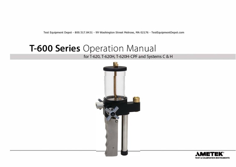
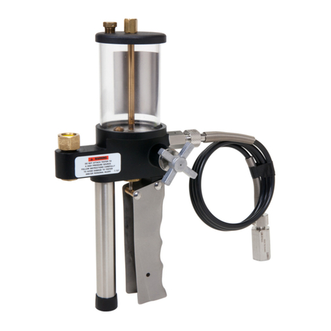
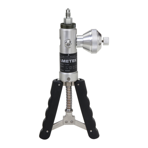
Ametek T User manual

Type T Series Operation Manual
for T, T-1, T-1-CPF, T-2, T-3, and Systems F

Contents
Overview ............................................................. 1
Introduction ............................................................1
Features and Parts Lists..................................................3
Safety Instructions ................................................ 6
Warnings, Cautions, and Notes...........................................6
Setup .................................................................. 7
Assembly ...............................................................7
Operation and Maintenance .................................... 9
Generating Pressure.....................................................9
Priming................................................................10
Connection Diagram ............................................. 13
Crystal Reference Indicators ............................................13
Specifications ...................................................... 14
Support .............................................................. 15
Troubleshooting .......................................................15
Fitting Kits and Spare Parts .............................................19
Appendix A: Assembly Drawings and Parts Lists..........................21
Contact Us.............................................................28
Returning product to AMETEK ..........................................28
Warranty ..............................................................28

Overview 1
TypeT Pump Operation Manual
Overview
INTRODUCTION
The Type T Series hand pump, mounted on a drip pan with a manifold assembly, is capable of producing pressures up to 1000 bar/15 000 psi.
These units are self-contained pressure sources designed to test instruments. They may be used to calibrate pressure gauges or to set hydraulic relief valves
and pressure switches. These units produce pressure to test components or systems, and work independently of other pressure sources. CPFversions include
Crystal Pressure Fittings (CPF), which allow users to produce leak-free seals without tools or thread tape. CPF ttings also include a self-venting weep hole to
help assure a safe disconnection from a pressurized system.
U.S. Patent No. 8,794,677
T, T-1, and T-2 pumps1may be ordered as part of a Pump System, complete with a JOFRA or Crystal Pressure Indicator. T-3 pumps ship as part of a complete
comparator testing kit, including four analog test gauges and necessary mounting tools and ttings, all housed in a rugged metal carrying case. For more
details on T-3 comparator testing kits, refer to T-3 Pumps for Hydraulic Comparator Kits on page 2.
All Type T Series Pump Systems include the most commonly used pressure ttings, seals, etc., all packaged in a carrying case with a custom insert.
1T designates a pump only. T-1 designates a pump with a manifold and tools. T-2 designates a pump with manifold, tools, and a carrying case.
T, T-1, and T-2 Pumps
Pressure Medium O-rings Pump System
T-1 Water *Buna-N FWB
T-1- CPF Oil or Water *Viton® FOV or FWV
T-1/VITON Water *Viton® FWV
T-1/EPT Water *EPT FWE
T-1/OIL Oil Buna-N FOB
T-1/OIL/VITON Oil Viton® FOV
T-1/OIL/EPT Oil EPT FOE
* Water is a 50/50 mixture of water and Isopropyl Alcohol.
TypeT Series Pump System

Overview 2
TypeT Pump Operation Manual
T-3 Pumps for Hydraulic Comparator Kits
X
With 160, 600, 5000, and 10 000 psi Gauges
Cal. Certication
with Data
Pressure
Medium O-rings
T-3 No Water *Buna-N
T-3/EPT No Water *EPT
T-3/VITON No Water *VITON
T-3/OIL No Oil Buna-N
T-3/OIL/EPT No Oil EPT
T-3/OIL/VITON No Oil VITON
T-3/C Yes Water *Buna-N
T-3/C/EPT Yes Water *EPT
T-3/C/VITON Yes Water *VITON
T-3/C/OIL Yes Oil Buna-N
T-3/C/OIL/EPT Yes Oil EPT
T-3/C/OIL/VITON Yes Oil VITON
X
With 30, 600, 3000, and 5000 psi Gauges
Cal. Certication
with Data
Pressure
Medium O-rings
T-3A No Water *Buna-N
T-3A/EPT No Water *EPT
T-3A/VITON No Water *VITON
T-3A/OIL No Oil Buna-N
T-3A/OIL/EPT No Oil EPT
T-3A/OIL/VITON No Oil VITON
T-3A/C Yes Water *Buna-N
T-3A/C/EPT Yes Water *EPT
T-3A/C/VITON Yes Water *VITON
T-3A/C/OIL Yes Oil Buna-N
T-3A/C/OIL/EPT Yes Oil EPT
T-3A/C/OIL/VITON Yes Oil VITON
X
With 2, 42, 210, and 350 kg/cm² Gauges
Cal. Certication
with Data
Pressure
Medium O-rings
T-3AM No Water *Buna-N
T-3AM/EPT No Water *EPT
T-3AM/VITON No Water *VITON
T-3AM/OIL No Oil Buna-N
T-3AM/OIL/EPT No Oil EPT
T-3AM/OIL/VITON No Oil VITON
T-3AM/C Yes Water *Buna-N
T-3AM/C/EPT Yes Water *EPT
T-3AM/C/VITON Yes Water *VITON
T-3AM/C/OIL Yes Oil Buna-N
T-3AM/C/OIL/EPT Yes Oil EPT
T-3AM/C/OIL/VITON Yes Oil VITON
X
With 200, 4000, 21000, and 35 000 kPa gauges
Cal. Certication
with Data
Pressure
Medium O-rings
T-3AN No Water *Buna-N
T-3AN/EPT No Water *EPT
T-3AN/VITON No Water *VITON
T-3AN/OIL No Oil Buna-N
T-3AN/OIL/EPT No Oil EPT
T-3AN/OIL/VITON No Oil VITON
T-3AN/C Yes Water *Buna-N
T-3AN/C/EPT Yes Water *EPT
T-3AN/C/VITON Yes Water *VITON
T-3AN/C/OIL Yes Oil Buna-N
T-3AN/C/OIL/EPT Yes Oil EPT
T-3AN/C/OIL/VITON Yes Oil VITON
X
With 11, 42, 350, and 700 bar gauges
Cal. Certication
with Data
Pressure
Medium O-rings
T-3/BARS No Water *Buna-N
T-3/BARS/EPT No Water *EPT
T-3/BARS/VITON No Water *VITON
T-3/BARS/OIL No Oil Buna-N
T-3/BARS/OIL/EPT No Oil EPT
T-3/BARS/OIL/VITON No Oil VITON
T-3/BARS/C Yes Water *Buna-N
T-3/BARS/C/EPT Yes Water *EPT
T-3/BARS/C/VITON Yes Water *VITON
T-3/BARS/C/OIL Yes Oil Buna-N
T-3/BARS/C/OIL/EPT Yes Oil EPT
T-3/BARS/C/OIL/VITON Yes Oil VITON
* Water is a 50/50 mixture of water and Isopropyl Alcohol.
T-3 Hydraulic
Comparator Testing Kit

Overview 3
TypeT Pump Operation Manual
FEATURES AND PARTS LISTS
Type T Series hand pumps may be ordered with either oil or a water/alcohol mixture as the pressure medium. There are three available seal packages for the
system: Buna-N, Viton®, and EPT.
All Type T Series hand pumps feature a vent valve, and dual volume control for rapid pressure increase at lower pressures and easier pumping at higher
pressures. T-1, T-2, and T-3 models include a dual pressure port manifold with ne adjust, plus replacement o-rings and a set of service tools.
Refer to Figure 3 on page 25 for more details on the included tools.
T-1 and T-2–
Included Parts
X
Reference and Device Under Test Pressure Ports
Part Number Description
T-134 15/16-20 Male to 1/4" NPT Female Adapter
T-135 15/16-20 Male to 1/2" NPT Female Adapter
T-1-CPF–
Included Parts
X
Reference and Device Under Test Pressure Ports
Part Number Description
5255 CPF Male to 15/16-20 Male Adapter (2)
4715 MP Female to 1/4" Female NPT Fitting
T-3 –
Included Parts
X
Reference and Device Under Test Pressure Ports
Part Number Description
T-134 15/16-20 Male to 1/4" NPT Female Adapter
T-135 15/16-20 Male to 1/2" NPT Female Adapter
– Set of 4 Test Gauges*
* For more details refer to T-3 Pumps for Hydraulic Comparator Kits on page 2
and to Figure 4 on page 26.
Pump Handle
Valve Rod Selector
CPF Fitting
Reservoir Tube
Vent Valve
Check Valve Plug
NPT Union Body
Fine Adjust
Manifold Assembly
Fill and Vent Relief Plug
Check Valve Plug

Overview 4
TypeT Pump Operation Manual
Hydraulic Fluid
Type T Series Pump Systems are only available delivered empty. You will still need to specify what uid type you are going to use (for example; FOV for Oil or FWV for Water).
Ordering a Pump System
Any Type T Series Pump System may be ordered with or without a reference indicator. The table below provides an explanation of the Pump System ordering
scheme when ordering a system without an indicator. For details on ordering the Pump Systems with an indicator, see the indicator datasheet.
Reference Indicator Reference Indicator Included Pump System
HPC500 Series ...HPC500 No...-NONE System F (T-1) .............-FWB
System F (T-1/Viton).......-FWV
System F (T-1/EPT) ........-FWE
System F (T-1/Oil) .........-FOB
System F (T-1/Oil/Viton) ...-FOV
System F (T-1/Oil/EPT).....-FOE
Parts Included with Pump Systems for JOFRA Reference Indicators
System F
FWB
(T-1)
FWV
(T-1/Viton)
FWE
(T-1/EPT)
FOB
(T-1/Oil)
FOV
(T-1/Oil/Viton)
FOE
(T-1/Oil/EPT)
Part Number Description
T-134 15/16-20 Male to 1/4" NPT Female Adapter
T-135 15/16-20 Male to 1/2" NPT Female Adapter
T-786 1/4" NPT Male to 1/4" BSP Female Fitting
127400 *1/4" NPT Male to 1/8" BSP Male Fitting
127401 *1/4" BSP Female to 1/8" BSP Male Fitting
127402 *1/8" Bonded Seals
60R120 1/4" Bonded Seals
404203 *Test Leads; Red & Black, including clips
60I104 Pack Tape (1 roll)
124004 Shoulder Strap
124304 Aluminum Carrying Case
* Included with HPC.
X
SAMPLE PART NUMBERS
HPC-NONE-FWB ..........System F pump system (for HPC500), for use with water.
HPC-NONE-FOE ...........System F pump system (for HPC500), for use with oil.
HPC500-700G-FOB........System F pump system for use with oil with a 0.82 to 35 bar HPC500 included.

Overview 5
TypeT Pump Operation Manual
Parts Included with Pump Systems for Crystal Reference Indicators
System F
FOV and FWV
(T-1-CPF)
Part Number Description
5255 CPF Male to 15/16-20 Male Adapter (2
)
MPF15K-1/4FPT CPF Female to 1/4" NPT Female Fitting
MPF-1/4BSPF CPF to 1/4" BSP Female Fitting
MPF-1/8MPT *1/8" MPT Fitting (for 30 Series Calibrator) (2
)
60R120 1/4" Bonded Seals (
5
)
1351 *Test Leads; Red & Black, including clips
5249 Protective Vinyl Cap (
4
)
60I104 Pack Tape (1 roll)
124004 Shoulder Strap
124304 Aluminum Carrying Case
* The MPF-1/8MPT ttings and 1351 Test Leads are included only with Pump Systems for the 30 Series Calibrator.
Ordering a Pump System
Any Type T Series Pump System may be ordered with or without a reference indicator. The table below provides an explanation of the Pump System ordering
scheme when ordering a system without an indicator. For details on ordering the Pump Systems with an indicator, see the indicator datasheet.
Reference Indicator Reference Indicator Included Pump System Liquid
nVision .........NV No...-NONE System F (T-1-CPF) ...-FOV Drained...-E
30 Series........IS30 System F (T-1-CPF) ...-FWV
XP2i ............XP2i
m1..............M1
HPC40 Series ...HPC40
X
SAMPLE PART NUMBERS
NV-NONE-FOV-E .......System F pump system (for nVision) drained of uid, for use with oil.
IS30-NONE-FWV-E ....System F pump system (for 30 Series) drained of uid, for use with water.
15KPSIXP2i-FWV-E ...System F pump system, drained, for use with water, with a 15 000 psi XP2i gauge included.
Hydraulic Fluid
Type T Series Pump Systems are only available delivered empty. You will still need to specify what uid
type you are going to use (for example; FOV for Oil or FWV for Water).

Safety Instructions 6
TypeT Pump Operation Manual
Safety Instructions
WARNINGS, CAUTIONS, AND NOTES
! WARNINGS:
• Do not connect any external pressure source to this instrument. This unit is designed to test pressure measuring devices connected to the manifold
only. Pressure from an external source can result in explosion of the liquid reservoir and possible bodily injury.
• This pump produces pressure up to 15 000 psi. The pressure rating of tubing and ttings used to connect the pump to the test device should exceed
15 000 psi.
• Do not operate above 15 000 psi/1000 bar.
! CAUTIONS:
• To prevent the reservoir from overowing upon venting, the volume of oil pumped should never exceed the reservoir volume.
• Never operate the pump without uid in the reservoir. The piston and o-rings require lubrication.
• Do not operate the ne adjust knob above 3500 psi.
• The vent plug must be open to operate this instrument.
Notes: All wetted parts are stainless steel, Monel, or Buna-N. Optional o-ring materials are Viton and EPT .

Setup 7
TypeT Pump Operation Manual
Setup
ASSEMBLY
1 Open the vent valve.
2 Attach the pressure manifold to the pump body.
Manifold Assembly

Setup 8
TypeT Pump Operation Manual
3 Close the vent valve.
Note: If using the T-1-CPF, ll with test uid through the gauge connections. This may take approximately 15 minutes.
Note: It may be necessary to prime the pump, particularly for rst time use, or if the pump has been inactive for an extended period of time.
Refer to Priming on page 10 for instructions on priming the pump.
4Pull the pump handle to the top of its stroke.
5 Pull out the valve rod selector to select the low pressure/high volume setting.
6 Gently operate the pump handle until test uid lls the top of the pressure ports on the pressure manifold.
Note: Lightly tap the manifold to make sure that any air bubbles sticking to the walls or in low ow areas are released to oat to the surface.
7 Attach the reference instrument and the device under test to the manifold.
Note: If CPF Fittings are used in your pressure system, remaining air can be purged by applying 10 psi or less and loosening the CPF tting closest to the pres-
sure device. When uid and air escape from the CPF weep hole, that portion of the system is purged. Repeat this process for each pressure device in the
pressure system which is connected to a CPF tting.
! CAUTION: Always choose a reference instrument with a range equal to or greater than the range of the device under test.
8 Ensure all connections are tight and leak free.

Operation and Maintenance 9
TypeT Pump Operation Manual
Operation and Maintenance
GENERATING PRESSURE
Note: It may be necessary to prime the pump, particularly if the pump has been inactive for an extended period of time. Refer to Priming on page 10
for instructions on priming the pump.
1Check that the vent ll plug is fully open by turning it counter-clockwise.
2 Open the vent valve.
Open the vent plug… then open the vent valve.
3 Set the valve rod selector to control your desired uid output volume.
! CAUTION: Only move the valve rod selector while the pump handle is stationary, in the up position.
Note: With the valve rod in the“out” position, uid ow will be at maximum and the maximum achievable pressure will be 1000 psi. To exceed 1000 psi,
push the valve rod in.
Low Pressure/
High Volume
High Pressure/
Low Volume

Operation and Maintenance 10
TypeT Pump Operation Manual
4 Zero the reference indicator and the device under test.
5 Close the vent valve.
6 Operate the pump handle to achieve a system pressure close to, but less than, your desired target pressure.
7 Pull the pump handle to the top of its stroke.
8 Push in the valve rod selector to select the high pressure/low volume setting.
9 Wait for the pressure to stabilize.
10 Carefully push down the pump handle to achieve the target pressure.
Note: Below 3500 psi, you may also use the ne adjust knob for small pressure adjustments.
11 After obtaining your readings, open the vent valve to vent the system.
! WARNING: The device under test and the reference indicator should only be removed when there is no pressure in the system.
PRIMING
All pumps are thoroughly tested at the factory before shipment. One of the most common diculties encountered is the loss of prime, which is evidenced by
an inability to build pressure. This is caused by entrapped air in the reservoir, which may collect in the high pressure/low volume check valve. When this oc-
curs, the pump will not develop pressure with the valve rod selector positioned in, to the high pressure/low volume setting. The following priming procedure
will correct the condition.
Note: For priming purposes, pump vigorously with full strokes of the hand lever.
Note: Verify the pump reservoir has sucient uid.
X
To Prime the Pump
1 Connect a reference indicator with a pressure range of at least 5000 psi to the manifold.
! CAUTION: Signicant pressure can develop during the priming process. Therefore, any device mounted to the manifold should have a range of at least
300 bar / 5000 psi. Alternately, all devices may be removed, and the manifold plugged.
2 Plug the remaining port of the manifold.
Manifold Plug

Operation and Maintenance 11
TypeT Pump Operation Manual
3 Pull the pump handle to the top of its stroke.
4 Open the vent valve.
5 Pull out the valve rod selector to select low pressure/high volume.
Open the vent valve… then select low pressure/high volume.
6 Pump ten full strokes.
7 Close the vent valve
8 Continue pumping to verify the low pressure/high volume setting operates properly and that the pump holds pressure.
9 Open the vent valve.
10 Pump ten more strokes.
11 Remove the high pressure/low volume check valve plug.

Operation and Maintenance 12
TypeT Pump Operation Manual
12 Slowly pump two and one-half strokes, positioning the pump lever at approximately 45 degrees, halfway through its stroke.
13 Allow system uid to ow out of the high pressure check valve, ushing entrapped air.
14 Examine the port for air bubbles which may adhere to the threads or parts.
Note: If air bubbles are present, repeat steps 12 through 14 until no more air bubbles appear.
15 Replace the high pressure/low volume check valve plug and tighten partially.
16 Use slight pressure on the hand lever to push system uid past the high pressure/low volume check valve plug to ensure complete purging of the
valve port.
17 Tighten the high pressure/low volume check valve plug.
18 Operate the pump handle until pumping becomes dicult.
19 Raise the pump handle.
20 Push in the valve rod selector to the high pressure/low volume position.
21 Resume pumping to verify the pump is operating properly.
Note: If the high pressure/low volume setting does not operate properly, there is more air trapped in the high pressure/low volume check valve. The priming
procedure must be repeated.

Connection Diagram 13
TypeT Pump Operation Manual
Connection Diagram
CRYSTAL REFERENCE INDICATORS
*These parts are included with the T-1-CPF pump.
Additional parts are supplied as part of a pump system, or may be ordered separately.
All BSP connections require bonded seals.
5255 *
5255 *
MPF-1/8QTM 1/8" Quick Test NPT Male
MPF-1/8MPT 1/8" NPT Male
MPF-1/4QTM 1/4" Quick Test NPT Male
MPF-1/4MPT 1/4" NPT Male
4501 1/8 NPT
4715 *1/4 NPT
4502 3/8 NPT
4503 1/2 NPT
MPF-1/8QTF 1/8" Quick Test NPT Female
MPF-1/4QTF 1/4" Quick Test NPT Female
MPF-1/4FPT 1/4" NPT Female
MPF-1/2QTF 1/2" Quick Test NPT Female
MPF-1/8BSPF G 1/8" Female
MPF-1/4BSPF G 1/4" Female
MPF-3/8BSPF G 3/8" Female
MPF-1/2BSPF G 1/2" Female
MPF-MPF Female to Female
MPF-MPFTU T-Union (Female)
MPF-MPFBULK Bulkhead (Female to Female)
MPF-CAP Cap
MPF-M20QTF M20 x 1.5 Quick Test Female
MPF-M20X1.5F M20 x 1.5 Female
MPF-QCN Quick-Connect Nut
MPF-AN4MAN4 Male
MPF-1/4TBM 1/4" Tube Male
MPF-3/8TBM 3/8" Tube Male
MPF-1/2TBM 1/2" Tube Male
MPF-5/16TRMfor Foxboro, Rosemount,
and Yokogawa
MPF-1/4TRMfor Honeywell
NPT MALE
NPT FEMALE
BSP
CPF
ADDITIONAL
TUBE
TRANSMITTER
Additional NPT sizes available in non-CPF MP adapters
4714 1/4 NPT
4494 3/8 NPT
4495 1/2 NPT
4496 3/4 NPT
4497 1/8 NPT
4498 1/4 NPT
4499 3/8 NPT
4500 1/2 NPT
4698 1/4 NPT
4492 3/8 NPT
4493 1/2 NPT
Medium Pressure MALE to NPT MALE
CPF Fittings Non-CPF MP Fittings
Medium Pressure FEMALE to NPT FEMALE
Medium Pressure FEMALE to NPT MALE
Medium Pressure MALE to NPT FEMALE
300 bar/5000 psi
5
700 bar/10000 psi
10
10
1000 bar/15000 psi
(Non-CPF MP adapters require wrench tightening.)
15
15
15
10
10
10
10
15
15
15
15
10
10
10
5
15
15
15
10
10
10
10
10
15
15
15
15
5
5
15
15
15
5
5
5
10
10
10
10
5
10
5
5
MPF-1/8MPT
Thread tape
required.

Specications 14
TypeT Pump Operation Manual
Specifications
Pressure Ranges
T, T-1, T-1-CPF, T-2, and T-3 . . . . . . .0 to 1000 bar / 0 to 15 000 psi
Recommended Test Fluids
The following uids are recommended for use with this pump:
Standard ............................. Distilled water or Isopropyl alcohol
Optional.............................. MGAAA oil
Other uids compatible with stainless steel, Monel, Buna N and Teon may be used. Optional Viton and EPT o-rings are available.
Volume............................... 30 oz (887 mL)
Low Volume / High Pressure Setting ... 2.8 to 3.2 cc per stroke
High Volume / Low Pressure Setting ... 3.0 to 4.0 cc per stroke
Pressure Connections
X
Reference Port
T-1, T-2, and T-3. . . . . . . . . . . . 1/4" FNPT or 1/2" FNPT
T-1-CPF. . . . . . . . . . . . . . . . . . . . CPF Male
X
Device Under Test Port
T-1, T-2, and T-3. . . . . . . . . . . . 1/4" FNPT or 1/2" FNPT
T-1-CPF. . . . . . . . . . . . . . . . . . . . 1/4" Female NPT
Note: Additional sizes, including metric ttings, are available. Contact us, or see our CPF datasheet for details.
Dimensions
Pump . . . . . . . . . . . . . . . . . . . . . 224 (L) x 127 (W) x 217 (H)* mm.
Weight . . . . . . . . . . . . . . . . . . . . 18.6 lbs / 8.4 kg
* Height includes manifold.

Support 15
TypeT Pump Operation Manual
Support
TROUBLESHOOTING
Failure to Pump
X
Problem: The pump fails to develop pressure when the hand lever is operated.
X
Solution: Verify that the vent valve is closed and that there is sucient uid in the reservoir. If necessary, add uid through the ll plug and follow the Pump
Priming Procedure.
If the failure continues, one or both of the check valves may be leaking. Use the following procedure to replace both the high pressure and low pressure o-rings.
X
To Replace the Check Valve O-rings
1 Raise the pump handle to the top of its stroke.
2 Position the valve rod selector for the o-ring you wish to replace.
(a) Pull out the valve rod selector to select the low pressure/high volume setting.
(b) Push in the valve rod selector to select the high pressure/low volume setting.
3 Remove the plug and o-ring from the port for the check valve o-ring you wish to replace.
Low pressure/high volume check valve plug and o-ring. High pressure/low volume check valve plug and o-ring.

Support 16
TypeT Pump Operation Manual
4 Remove the check valve spacer, spring, valve poppet, and check valve o-ring.
5 Inspect the check valve o-ring, and replace it if necessary. Then re-install the o-ring, valve poppet, spring, and check valve spacer.
6 Slowly pump two and one-half strokes, positioning the pump lever at approximately 45 degrees, halfway through its stroke.
7 Allow system uid to ow out of the low pressure check valve, ushing entrapped air.
8 Examine the port for air bubbles which may adhere to the threads or parts.
Note: If air bubbles are present, repeat steps 2 through 5 until no more air bubbles appear.
9 Install the check valve plug and o-ring and tighten partially.
10 If installing the low pressure/high volume check valve plug... Tighten the check valve plug.
The procedure for the low-pressure/high volume side is now complete.
11 If installing the high pressure/low volume check valve plug... Use slight pressure on the hand lever to push system uid past the high
pressure/low volume check valve plug to ensure complete purging of the valve port.
12 Tighten the high pressure/low volume check valve plug.
13 Operate the pump handle until pumping becomes dicult.
14 Raise the pump handle to the top of its stoke.
15 Push in the valve rod selector to the high pressure/low volume position.
16 Resume pumping to verify the pump is operating properly.
Check Valve Spacer
Spring
Valve Poppet
Check Valve O-ring

Support 17
TypeT Pump Operation Manual
Pump Does Not Hold Pressure
X
Problem: The pump operates but the pressure declines beyond normal adiabatic eects.
X
Solution: One of two o-rings may be leaking. As the pressure drops, observe the hand lever. If the hand lever rises, the discharge check valve is leaking and
its o-ring should be replaced.
X
To Replace the Discharge Check Valve O-ring
1 Remove the plug and o-Ring from the front of the pump body.
2 Use a screwdriver to loosen and remove the retaining plug. then remove the guide rod, spring, valve poppet and check valve o-ring.
3 Inspect the check valve o-ring, and replace it if necessary. Then re-install the o-ring, valve poppet, spring, and guide rod.
4 Thread in the retaining plug until it is tightly seated. Then back o 3 ½ turns to provide sucient travel for the valve poppet.
5 Install the check valve plug and o-ring.
Guide Rod
Retaining Plug
Spring
Valve Poppet
Check Valve O-ring

Support 18
TypeT Pump Operation Manual
X
To Replace the Vent Valve O-ring
1 Apply a wrench to the nut at the base of the pressure relief valve.
2 Remove the vent valve and its o-ring.
3 Remove the relief valve seat and its o-ring.
4 Inspect the relief valve seat o-ring, and replace it if necessary. Then re-install the o-ring, valve poppet, spring, and guide rod.
5 Install the vent valve and o-ring.
Relief Valve Seat O-ring
Relief Valve Seat
This manual suits for next models
7
Table of contents
Other Ametek Water Pump manuals
Popular Water Pump manuals by other brands

Aquascape Pro
Aquascape Pro Pondless 49000 Instructions & maintenance

salmson
salmson LRLA Installation and starting instructions

Circor
Circor IMO CIG Product service manual

Grundfos
Grundfos DDE Installation and operating instructions

Reef Factory
Reef Factory Base pump 3000 Manual instruction

Nakayama
Nakayama SP1040 quick start guide

Graco
Graco Husky 1050HP repair parts

GE
GE PV411A instruction manual

Becker
Becker VT 4.16 operating instructions

baracuda
baracuda 0327405 Installation & operating instructions

WITA
WITA Delta Maxi 70 Series TRANSLATION OF THE ORIGINAL INSTALLATION AND OPERATING INSTRUCTIONS

KTM
KTM TRILINE Operation and maintenance manual