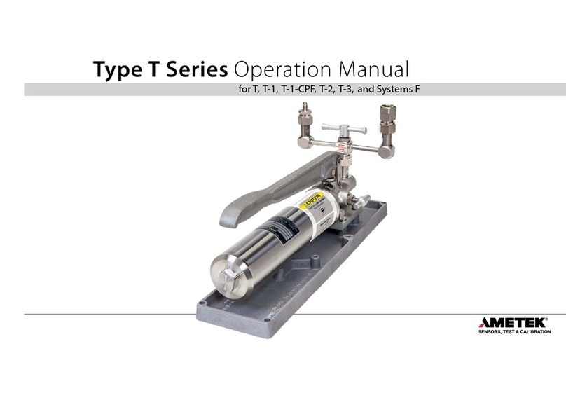
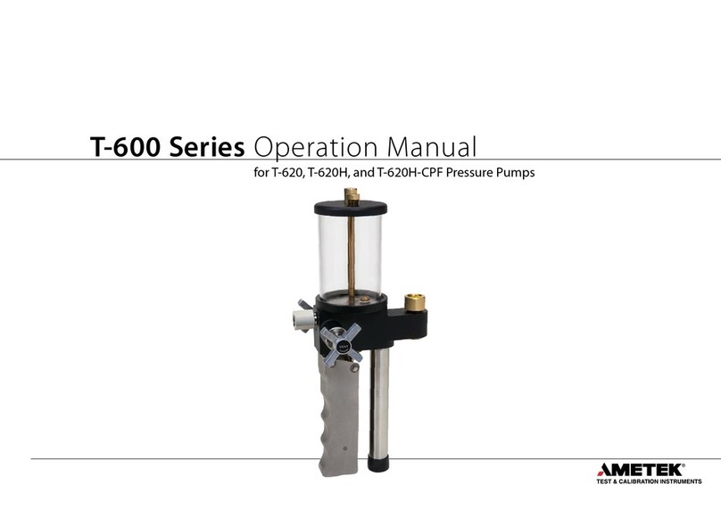
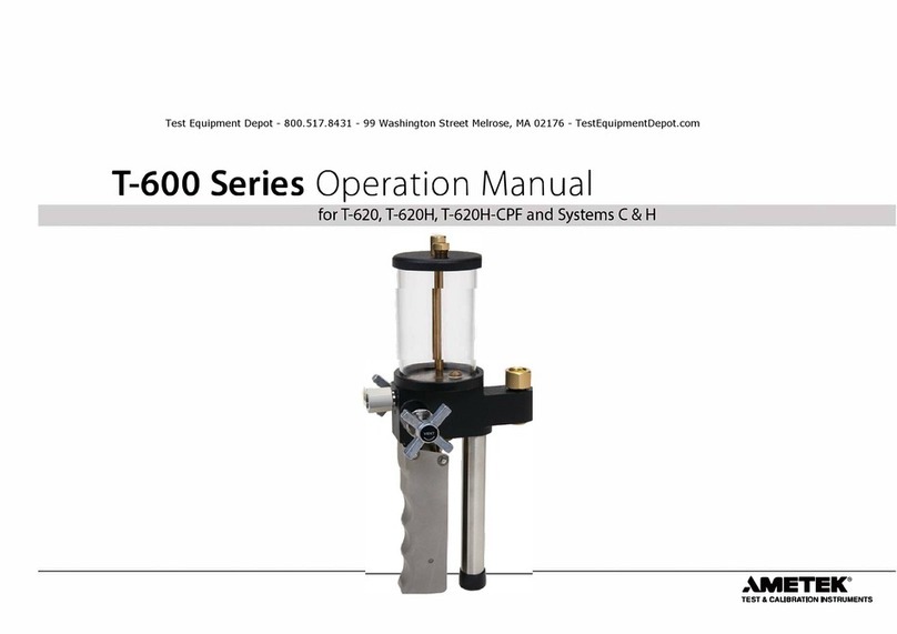
Ametek T-620 User manual

User Manual
Pressure Calibration System C
and Hydraulic Pressure Pump
Models T-620/T-620H
Copyright 2008 AMETEK Denmark A/S

2 18-06-2008 126682 00
About this manual….
• The structure of the manual
This user manual is aimed at users who are familiar with
JOFRA Pressure Calibration Systems, as well as those who are
not. The manual is divided into 9 chapters, which describe how
to set up, operate, service and maintain the pressure calibration
system. The technical specifications are described and
accessories may be ordered from the list of accessories.
• Safety symbols
This manual contains a number of safety symbols designed to
draw your attention to instructions, which must be followed
when using the instrument, as well as any risks involved.
Warning
Events, which may compromise the safe use of
the instrument and result in considerable
personal or material damage.
Caution…
Events, which may compromise the safe use of
the instrument and result in slight personal or
material damage.
Note…
Special situations, which demand the user’s
attention.

126682 00 18-06-2008 3
List of contents
1.0 Introduction ..............................................................................4
2.0 Safety instructions ...................................................................6
3.0 Identifying your JOFRA Pressure Calibration System .........8
3.1 Model description.......................................................................... 8
3.2 Receipt of the JOFRA Pressure Calibration System C ............... 8
4.0 Operating instructions...........................................................10
4.1 Operating the T-620/T-620H pump. ........................................... 12
4.2 Media’s to be used...................................................................... 14
5.0 Errors.......................................................................................15
6.0 Returning the JOFRA Pressure Calibration System for
service .....................................................................................18
7.0 Maintenance............................................................................20
7.1 Cleaning...................................................................................... 20
8.0 Technical specifications........................................................21
9.0 List of accessories and spare parts .....................................23
9.1 System C with DPC-500 calibrator ............................................. 23
9.1.1 Exploded view – System C with DPC-500 calibrator..... 24
9.2 System C with APC calibrator..................................................... 25
9.2.1 Exploded view – System C with APC calibrator ............ 27
9.3 System C with IPI indicator......................................................... 28
9.3.1 Exploded view – System C with IPI indicator................. 29
9.4 System C with APM-S pressure module .................................... 30
9.4.1 Exploded view – System C with APM-S pres. module .. 31
9.5 System C with APM-H pressure module .................................... 32
9.5.1 Exploded view – System C with APM-H pres. module .. 33

4 18-06-2008 126682 00
1.0 Introduction
Congratulations on your new JOFRA Pressure
Calibration System!
With the JOFRA Pressure Calibration System, you have chosen an
extremely effective pressure system, which we hope will live up to all
your expectations. Over the past many years, we have acquired
extensive knowledge of industrial precision pressure calibration. This
expertise is reflected in our products, which are all designed for daily
use in an industrial environment. Please note that we would be very
interested in hearing from you if you have any ideas or suggestions
for changes to our products.
This user manual applies to the following systems:
• System C
• Hand pump, models T-620, T-620H
Available instruments * :
- DPC-500
- APC
- IPI
- APM-S/H
(* See separate manuals for the instruments)
ISO-9001 certified
AMETEK Denmark A/S was awarded the ISO-9001 certificate in
September 1994 by - Bureau Veritas Certification Denmark.

126682 00 18-06-2008 5
Technical assistance
Please contact the dealer from whom you acquired the pressure
system if you require technical assistance.
Guarantee
According to current terms of sale and delivery.
This guarantee only covers defects in manufacture and becomes
void if the Pressure Calibration System has been subject to
unauthorised intervention and/or misuse.

6 18-06-2008 126682 00
2.0 Safety instructions
Read this manual carefully before using
the system!
Please follow the instructions and procedures described in
this manual. They are designed so that you get the most
out of your pressure system and avoid any personal
injuries and/or damage to the system.
Warning……
About the handling:
• Avoid knocking, bumping or dropping the pressure
system. This can cause permanent damage to the
system and loss of accuracy.
About the use:
• The pressure system must not be used for any
purposes other than those described in this manual and
for any application other than precision pressure
calibration jobs.
• The pressure system should only be used by TRAINED
PERSONNEL.
• Never subject the pressure gauges to overpressure. In
case of overpressure the gauge should not be used for
calibration purposes.
• None of our calibration systems are cleaned or
prepared for OXYGEN MEDIUMS so DO NOT USE our
systems for this purpose.
• Do not disconnect any parts from the system when
pressurised.
• Do not connect any external pressure source to this
system. This system is designed to test pressure
measuring devices connected to the manifold only.
Pressure from an external source can result in
explosion of the liquid reservoir and possible personal
injuries.

126682 00 18-06-2008 7
Note…
The product liability only applies if the pressure system is
subject to a manufacturing defect. This liability becomes
void if the user fails to follow the maintenance instructions
set out in this manual or uses unauthorised spare parts.

8 18-06-2008 126682 00
3.0 Identifying your JOFRA Pressure
Calibration System
3.1 Model description
The T-620/T-620H hydraulic pressure hand pumps are specially
designed for high pressure applications. The pumps are compatible
with petroleum-based oils or hydraulic fluids.
The T-620 pump generates up to 200 bar (3,000 psi) and the T-620H
pump generates up to 350 bar (5,000 psi).
All pumps feature a 0.5 pint/200 cl built-in oil reservoir, vent valve and
vernier valve for fine adjustment. The pumps have dual pressure
output – one for the test object and one for the indicator. Easy
connection between pump and indicator.
The System C can be used with one of the following instruments :
DPC-500, APC, IPI, APM-S/H or together with either a T-620 or a T-
620H hydraulic pressure hand pump depending on the chosen
pressure range.
3.2 Receipt of the JOFRA Pressure Calibration
System C
The Pressure Calibration System C is delivered complete assembled
as standard in a carrying case and should always be placed in the
carrying case after use.
When you receive the Pressure Calibration System C…
• Carefully unpack and check the pump, the instrument and the
accessories.
• Check the parts off against the list shown below.
If any of the parts are missing or damaged, please contact the
dealer from whom you acquired the Pressure Calibration System.

126682 00 18-06-2008 9
You should receive:
• 1 pump T-620/T-620H
• 1 hose 20“/0.5m with ¼“ BSP and NPT female connector
• 1 roll of teflon tape
• 1 aluminium carrying case
• 1 calibration certificate
• 1 user manual for pump system
Additional for System C with DPC-500 calibrator:
o 1 extension cable 2 m between DPC-500 and DPC-J reference
sensor
o 1 battery charger
o 1 test lead : red
o 1 test lead : black
o 1 connection cable for USB
o 1 DPC-CAL calibration software
o 1 JOFRACAL calibration software
o 1 DPC-J reference sensor
o 1 user manual for DPC-500
Additional for System C with APC calibrator:
o 1 9V battery
o 1 adapter to ¼” NPT female
o 1 adapter to ¼” BSP female
o 1 test lead : red
o 1 test lead : black
o 1 soft case and shoulder strap
o 1 user manual for APC
Additional for System C with IPI indicator:
o 3 AA batteries
o 1 protective boot
o 1 adapter to ¼” BSP male
o 1 user manual for IPI

10 18-06-2008 126682 00
4.0 Operating instructions
Warning……
About the handling:
• Avoid knocking, bumping or dropping the pressure
system. This can cause permanent damage to the
system and loss of accuracy.
About the use:
• Do not attach the pump to a high pressure source.
Please notice that the pump comes in 2 different
pressure ranges. Therefore it is very important to check
the version of the pump to avoid over pressure of
indicator.
Follow these instructions carefully to avoid damage to
the system and/or personal injuries.
• The pressure system must not be used for any
purposes other than those described in this manual and
for any application other than precision pressure
calibration jobs.
• Never subject the pressure gauges to overpressure. In
case of overpressure the gauge should not be used for
calibration purposes.
• The pressure system should only be used by TRAINED
PERSONNEL.
• None of our calibration systems are cleaned or
prepared for OXYGEN MEDIUMS so DO NOT USE our
systems for this purpose.
• Do not disconnect any parts from the system when
pressurised.
• Do not connect any external pressure source to this
instrument. This unit is designed to test pressure
measuring devices connected to the manifold only.
Pressure from an external source can result in
explosion of the liquid reservoir and possible personal
injuries.

126682 00 18-06-2008 11
Fig 1
POS DESCRIPTION
1 Fill plug
2 End plug
3 Fitting ¼” NPT male til ¼” BSP female
4 Needle valve
5 Moveable handle
6 Vernier valve
7 Pressure port
8 Pressure port
1/4" NPT female
1/4" NPT female
1/4" BSP female
1/4" NPT male
1
2
3
4
6
5
7
8

12 18-06-2008 126682 00
4.1 Operating the T-620/T-620H pump.
Warning
Do not attach the pump to a high pressure source. Follow
these instructions carefully to avoid damage to the pump
and/or personal injuries.
This routine must be followed in order to operate the system correctly
(see fig. 1 accordingly).
1. If the pump has been ordered alone without system C, the
reservoir will be empty. Remove the fill plug (ref. 1) on the
top of cap and fill the reservoir approximately 2/3 full of fluid.
Caution…
Do not use solvents or synthetic fluids that will adversely
affect the operation of the pump.
Connect and tighten fill plug.
Ordering system C the reservoir will be supplied with the
fluid ordered from our factory.
2. Remove plug (ref. 2) and attach gauge or pressure device to
be calibrated to the 1/4" BSP hose fitting (ref. 3). Tighten
threads loosely.
Note…
After connection of all parts and before pressure is created,
the air can be released from the system by loosening the
connectors (pos. 3). It is now possible to pump out oil and
air until no air is left in the oil.
3. Turn needle valve (ref. 4) on left side of the pump counter
clockwise until fully open.
4. Pump the movable handle (ref. 5) until the test fluid is
evident at the thread connection.

126682 00 18-06-2008 13
The hose may be pre-filled with test fluid on the initial start
up to help speed the operation of the pump.
5. Tighten firmly the thread connection of the hose end and
device to be tested.
6. Switch the indicator on (for operation see separate manual).
7. Continue to pump the movable handle until the air bubbling
in the reservoir stops.
8. Secure that the pressure system is pressureless by opening
the needle valve (ref. 4), and zero set the indicator (See
manual for indicator systems).
9. Turn the needle valve (ref. 4) clockwise until it is tight by
hand only.
10. Pump movable handle until the approximate desired
pressure is obtained on the indicator.
11. Turn the vernier valve (ref. 6) on the right side of the pump
until the exact calibration test pressure is obtained.
After calibration
1. Upon completion of calibration testing, turn the needle valve
counter clockwise to release the pressure to 0 BAR.
2. Remove the test object.
3. Replace plug (ref. 2) in open end of hose to prevent fluid
leakage.
4. Clean all parts and store in the carrying case.

14 18-06-2008 126682 00
4.2 Media’s to be used
Recommended test fluids to be used are :
• Petroleum based oils
• Hydraulic fluids
The fluids are compatible with the aluminium, brass, stainless steel,
Teflon, Lexan and Buna N wetted pump parts.
Other fluids
Contact your local distributor if you want to use other fluids than
those stated above.

126682 00 18-06-2008 15
5.0 Errors
Generally the JOFRA Pressure Calibration System is manufactured
for field use and will normally cause no problems for the user.
Note…
AMETEK Denmark’s liability ceases if:
• parts are replaced/repaired using spare parts which are
not identical to those recommended by the manufacturer.
• non-original parts are used in any way when operating
the system.
AMETEK Denmark’s liability is restricted to errors, which
originated from the factory.
The questions and answers in the following schedule are based on
the use of an indicator with a pump system.

16 18-06-2008 126682 00
FAILURE CAUSE ACTION
The pressure is
not stabilising.
• The system may be
leaking.
o The compression of
media includes air.
If you have a hose in
the pressure loop -
the hose will expand
and give some
movement.
Adiabatic and
thermodynamic
effects are present
within all pressure
systems.
• Check all
connections.
o You may have to
adjust the pressure a
few times before the
pressure is stable
enough for
calibration.
Release air.
(See Note page 13)
The effect will
disappear rapidly.
The effect will
disappear rapidly.
The system fails
to indicate a
pressure
increase after
considerable
pumping action
of the handle.
• The threaded
connection between
the hose end and
the attached
instrument is not
tight.
o A pressure increase
can still not be
obtained.
• Check all
connections.
o The system is in
need of service.
Please contact your
local distributor or
AMETEK Denmark
A/S for advice.

126682 00 18-06-2008 17
Note…
Always readjust the pressure after 5 – 10 minutes to allow
time for settling of above effects.
When you operate with high pressure the sensitivity of the
system is high with regard to temperature and movements.

18 18-06-2008 126682 00
6.0 Returning the JOFRA Pressure
Calibration System for service
When in need of service please contact your local distributor for
advice or return the system to the manufacturer.
For all pressure systems, the pump and the indicator are separate
systems. Therefore, a replacement of the pump does not mean that
the complete system has to be sent in for repair.
Recalibration of the unit can be performed locally with an accurate
pressure reference : No need to send the unit back to the
manufacturer for recalibration. If a factory calibration is required, the
pump and indicator are independent and only the indicator needs to
be returned.
When returning the Pressure Calibration System to the manufacturer
for service, please enclose a fully completed service information form.
Simply copy the form on the following page and fill in the required
information.
The Pressure Calibration System should be returned in the original
packing.

126682 00 18-06-2008 19
Service info
Customer data: Date:
Customer name and address:___________________________________________
Attention and Dept.:___________________________________________________
Fax no./Phone no.:____________________________________________________
Your order no.:_______________________________________________________
Delivery address:_____________________________________________________
Distributor name:_____________________________________________________
Instrument data:
Model and Serial no.:__________________________________________________
Warranty claimed Yes:____ No:_____ Original invoice no.:_________________
___________________________________________________________________
Temp. Service request: This instrument is sent for
calibration (please tick off):
___ Calibration as left ___ Check
___ Calibration as found and as left ___ Service
___ Accredited calibration as left ___ Repair
___ Accredited calibration as found and as left.
___________________________________________________________________
Diagnosis data/cause for return:
Diagnosis/Fault description:_____________________________________________
___________________________________________________________________
Special requests:_____________________________________________________
___________________________________________________________________
Safety precautions: if the product has been exposed to any hazardous substances, it must be
thoroughly decontaminated before it is returned to AMETEK Denmark A/S. Details of the
hazardous substances and any precautions to be taken must be enclosed.

20 18-06-2008 126682 00
7.0 Maintenance
7.1 Cleaning
Users should/must carry out the following cleaning procedures as and
when required:
• The exterior of the instrument - Clean using water and a soft
cloth.
The cloth should be wrung out hard to avoid any water
penetrating the calibrator and causing damage.
The instrument may also be cleaned using isopropyl alcohol
when heavily soiled.
Other manuals for T-620
1
This manual suits for next models
1
Table of contents
Other Ametek Water Pump manuals
Popular Water Pump manuals by other brands

Pentair
Pentair Myers 4VL Installation and service manual

Regulus
Regulus CSE OTS MFB+ZV G Installation and operation manual

Grundfos
Grundfos DMH 28 Series Installation and operating instructions

Golander pump
Golander pump DT15-14 user guide

Idex
Idex Warren Rupp MARATHON M20 Service & operating manual

The Fountainhead Group
The Fountainhead Group D.B. Smith Indian Smokechaser Pro use and care manual