AMF-BRUNS EasyPull User manual

Operating Instructions
www.amf-bruns.de
EASYPULL


Foreword
EasyPull Page 3 of 48
Foreword
Dear reader,
These Operating Instructions serve to provide all information required
for the safe use of the EasyPull.
The EasyPull is designed and constructed in accordance with state-
of-the-art technology and recognised safety standards. Persons and
materials can however be endangered, as not all danger areas can
be eliminated if the functional capability is to be maintained. Accidents
caused by these dangers can however be prevented by strictly ob-
serving these Operating Instructions. Over and above this, the opera-
tional efficiency of your EasyPull can be used to the full and unneces-
sary faults can be prevented.
After reading these Operating Instructions for the first time, keep them
in a safe place for future reference over the entire lifetime of the Easy-
Pull. If you sell the EasyPull, hand these Operating Instructions over to
the new owner.
All details, figures and dimensions contained in these Operating In-
structions are non-binding. They cannot be used as the basis for any
claims whatsoever.
This document must not be reproduced or duplicated,
in full or in part, without the prior, written permission of the manufac-
turer.
The EasyPull must be converted or modified in any way, without see-
king the prior, written permission of the manufacturer. The manufac-
turer will not be held responsible in any way whatsoever if conversions
or modifications are carried out without authorisation.
Use only original spare parts or spare parts which have been appro-
ved of by the manufacturer. If spare parts other than these are used,
this can have a negative effect on the specified characteristics, the
functionality and safety of the EasyPull. Using non-original or unautho-
rised spare parts will render the guarantee null and void.
Contact our customer services department to order spare parts or
accessories (see Chapter 12, page 46).
Foreword
Page 4 of 48 EasyPull
Explanation of symbols and signs
To improve understanding, the following conventions should be met
for these Operating Instructions:
1.
The following conventions are used to highlight important information:
DANGER!
y warns of a situation of immediate danger, which will lead to severe
or fatal injuries if not avoided.
W
ARNING!
y warns of a potentially dangerous situation, which will lead to severe
or fatal injuries if not avoided.
CAUTION!
y warns of a potentially dangerous situation, which will lead to slight
or minor injuries or material damage if not avoided.
A
TTENTION!
...indicates a potentially dangerous situation, which can cause mate-
rial damage if not avoided.
...contains general notes and useful information.
...gives a reference to important information in other sections and
documents.
2.
Some text passages serve a special purpose. These are identified as
follows:
y Lists.
Instructional text, e.g. a sequence of activities.

Foreword
EasyPull Page 5 of 48
3.
Meaning of directions:
If directions are given in the text (in front of, front, behind, rear, right,
left), these directions relate to the normal direction of travel of the
vehicle.

Contents
Page 6 of 48 EasyPull
Contents
1 Safety ..............................................................................8
1.1 Proper Use........................................................................... 8
1.2 Improper Use....................................................................... 9
1.3 Operator Requirements ....................................................... 9
1.4 Product Monitoring .............................................................10
1.5 Safety and Accident Prevention Regulations.......................10
1.6 Disposal .............................................................................. 11
2 Description ..................................................................... 11
2.1 Layout and Function ........................................................... 11
2.1.1 Voltage transformer ................................................. 11
2.1.2 Control unit...............................................................12
2.1.3 Winch with belts .......................................................13
2.1.4 Remote control.........................................................14
2.1.5 Rating plates ............................................................15
2.2 Technical Data ....................................................................16
3 Transportation............................................................... 16
4 Installation ..................................................................... 17
4.1 Safety Information for Installation ........................................ 17
4.2 Fitting the Winch .................................................................18
4.3 Installing and Connecting the Electrical System ..................19
4.3.1 Fitting the voltage transformer .................................19
4.3.2 Fitting the control unit.............................................. 20
4.3.3 Laying the extension cable (optional) .......................21
4.3.4 Laying the connection cable.................................... 22
4.3.5 Fitting the Door Contact Switches ........................... 22
4.3.6 Making the connections .......................................... 23
4.4 Tightening Torques ............................................................ 24
4.5 Carrying out a trial run ....................................................... 25
5 Commissioning ............................................................. 26
5.1 Initial Setting....................................................................... 26
5.2 Checking the Setting.......................................................... 29
5.3 Fine Adjustment ................................................................. 30
6 Operation....................................................................... 31
6.1 Safety Regulations for Operation ........................................31
6.2 Loading an Occupied or Unoccupied Wheelchair .............. 32
6.3 Unloading an Occupied or Unoccupied Wheelchair ........... 34

Contents
EasyPull Page 7 of 48
7 Maintenance and Repair ...............................................36
7.1 Safety Regulations for Maintenance and Repair.................36
7.2 Routine Maintenance Work ................................................ 37
7.2.1 Maintenance schedule............................................. 37
7.2.2 Maintenance record ................................................38
7.3 Maintenance and Repair Record........................................38
8 De-Commissioning and Conservation ..........................39
9 Faults and Troubleshooting ..........................................39
9.1 Fitting a New Battery..........................................................40
9.2 Configuring a New Remote Control ................................... 41
10 Spare parts ...................................................................43
11 Electrical Circuit Diagrams ...........................................44
12 Customer Service .........................................................46
13 Declaration of Conformity.............................................47

Safety
Page 8 of 48 EasyPull
1 Safety
CAUTION!
Risk of injury if the EasyPull is not operated correctly.
Therefore:
y It is imperative, that these Operating Instructions are read thoroug-
hly before operating the EasyPull. Always follow the instructions
and information therein, particularly the safety instructions.
y If these Operating Instructions or parts thereof are lost or become
illegible, please request a new copy from the manufacturer.
Prerequisite to the safe handling and trouble-free operation of the
EasyPull is a thorough knowledge of the applicable safety information
and the safety regulations.
It is therefore imperative that this Chapter is read thoroughly before
operating the EasyPull and that the instructions and warnings herein
are strictly observed. The safety information and warnings, given at
the appropriate places in the following Chapters, must also be strictly
observed. The manufacturer will not be held responsible if safety in-
formation and warnings are not adhered to.
In addition to the information given in these Operating Instructions,
local legislative regulations must be taken into consideration, in parti-
cular those regarding safety and accident prevention.
1.1 Proper Use
The operational reliability of the EasyPull is only guaranteed if it is put
to proper use. It must therefore only be used for the purpose for
which it is intended.
The EasyPull is only deemed to be in proper use when it is used to
pull wheelchair-bound persons or unoccupied wheelchairs into vehic-
les that are specifically designed or converted to transport disabled
persons. The vehicle must be fitted with an access ramp for this pur-
pose. The EasyPull only secures the front of the wheelchair. For trans-
portation, the wheelchair must be secured with additional belts at the
rear. The passenger in the wheelchair must wear a safety belt.
Proper use also includes strict adherence to the information given in
these Operating Instructions.

Safet
y
EasyPull Page 9 of 48
W
ARNING!
If the EasyPull is used for any other purpose than that described
above, this may result in dangerous situations for persons or material
damage being caused.
Therefore:
y Only use the EasyPull for the purpose for which it was intended.
y Always adhere to information given in these Operating Instructions.
y Do not use the EasyPull for any other purposes, particularly those
given in Section 1.2. These are deemed to be improper use.
1.2 Improper Use
Any use other than that described in Section 1.1 is deemed to be im-
proper use.
These include in particular:
y Pulling any objects other than wheelchair-bound persons or unoc-
cupied wheelchairs.
y Allowing operation by incompetent operators.
y Making unauthorised modifications to the EasyPull.
y Operating the Swivel Lift when it has safety-relevant faults or is in
a faulty condition.
1.3 Operator Requirements
The EasyPull must only be handled by persons who:
y have read and understood these Operating Instructions and
y have the technical knowledge to operate the parking brakes on
wheelchairs
Over and above this, the following applies if the EasyPull is used com-
mercially or communally:
The EasyPull must only be operated by persons who:
y are of legal age,
y have been instructed in how to operate the EasyPull,
y have been expressly assigned to do so by
the owner and
y are in a position to adapt themselves to the particular behaviour
and needs of disabled persons.
Transportation, installation, commissioning, maintenance, repair, fault
finding and disposal of the EasyPull must only be carried out by per-
sons with the corresponding technical training and experience.

Safety
Page 10 of 48 EasyPull
1.4 Product Monitoring
Please contact AMF-Bruns GmbH & Co. KG immediately if faults or
problems are encountered when operating the EasyPull or if ac-
cidents or "near-misses" occur.
AMF-Bruns will effect a solution to the problem with your help and the
knowledge gained will flow into future projects.
NOTE
Guarantee work on the EasyPull must only be carried out with the
prior agreement of AMF-Bruns GmbH & Co. KG.
The costs of such work will not be accepted by AMF-Bruns without
prior agreement.
1.5 Safety and Accident Prevention
Regulations
Adhere to the following notes in order to prevent personal injuries and
material damage. For commercial use, also adhere also to the rele-
vant safety and accident prevention regulations laid down by the trade
associations.
y The EasyPull must only be used for the purpose for which it is in-
tended, otherwise dangerous situations, with resultant injuries,
may occur (Proper use: see Section 1.1, page 8).
y The owner is responsible for ensuring that proper use is adhered
to, in particular that the EasyPull is only operated by authorised
persons.
y If the EasyPull is used commercially or as a public utility, the owner
must ensure that operating personnel are familiar with the opera-
tion of the EasyPull under all operating conditions by providing trai-
ning courses.
y Proper use of the EasyPull also includes adherence to the specified
maintenance and repair work, in particular strict adherence to the
maintenance intervals. If such work is not carried out, trouble-free
operation cannot be guaranteed. There is a risk of personal injury
and material damage being caused.
y The EasyPull must not be operated in a faulty condition, as serious
injuries may be caused by this. If faults occur, do not use the Easy-
Pull until repairs have been effected.
y Use only original spare parts and accessories or those approved
of by the manufacturer. If other parts are used, the manufacturer
will not accept liability for the consequences.
Description
EasyPull Page 11 of 48
1.6 Disposal
When the EasyPull's useful life has expired, it must only be disposed
of by qualified specialists. The manufacturer will accept no liability for
damage caused by incorrect disposal.
2 Description
Wheelchairs are pulled into a vehicle by the EasyPull. To enable this,
the vehicle must be equipped with an access ramp
2.1 Layout and Function
The EasyPull comprises the following main components:
y Voltage Transformer
y Control unit
y Winch with belts
y Remote Control
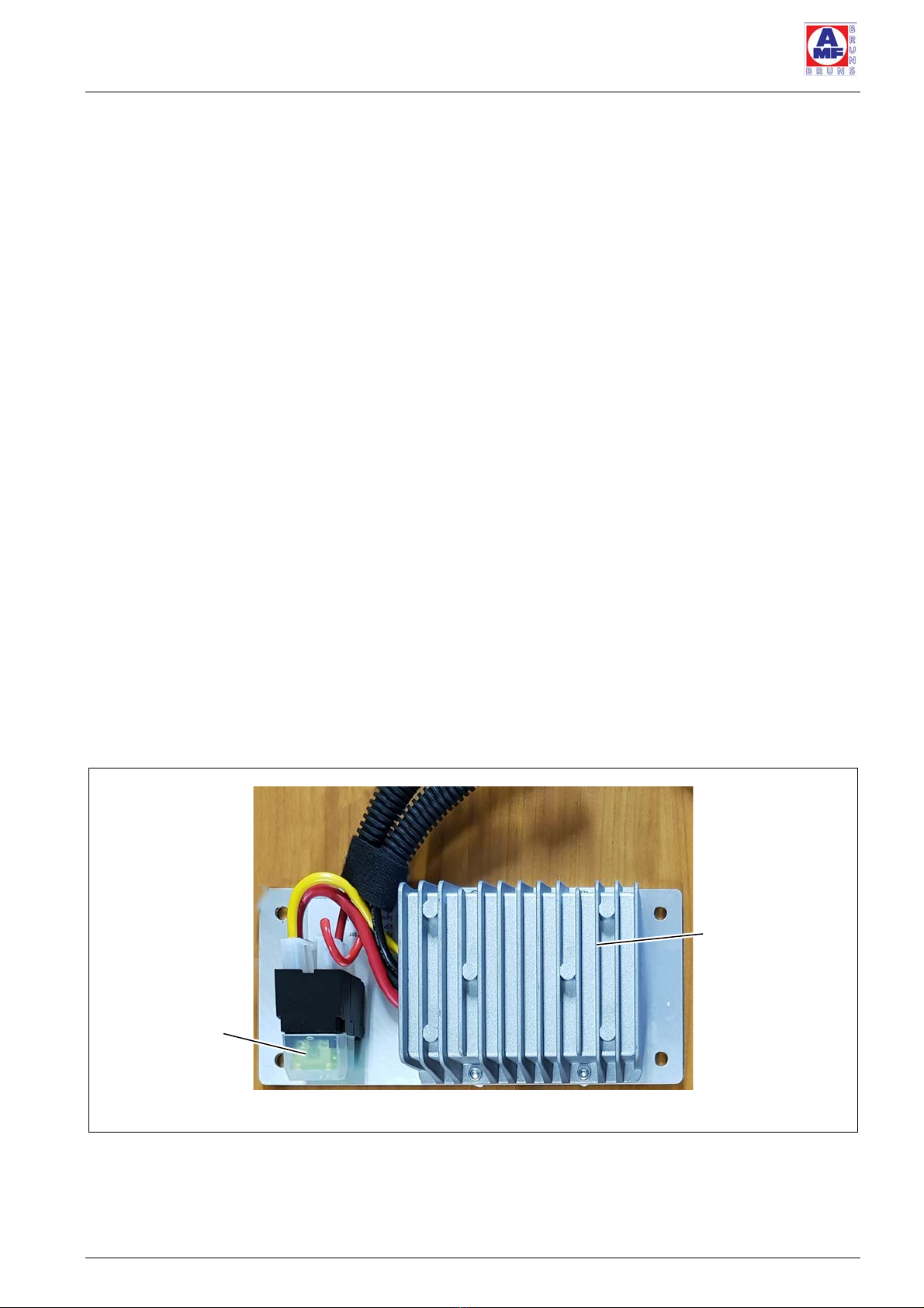
2.1.1 Voltage transformer
The voltage transformer (see Figure 1) generates the power supply
voltage (24 V DC) for the control system and winch from the vehicle’s
battery voltage. The primary and secondary sides of the voltage
transformer are protected by fuses.
Figure 1
:
Voltage Transformer
Fuses
Heat sink
Description
Page 12 of 48 EasyPull
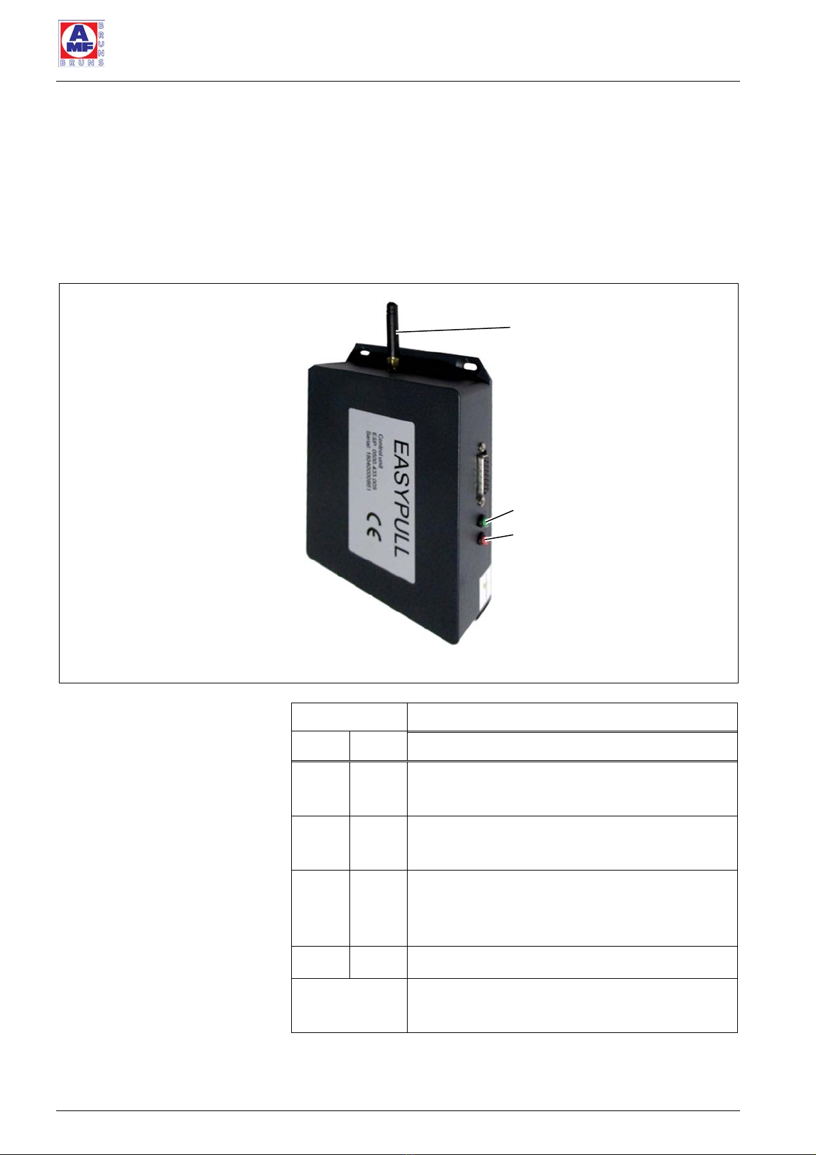
2.1.2 Control unit
The control unit (see Figure 2) contains the receiver for the remote
control and the electronics to control the winch. The door contact
switch connected to the control unit switches the power supply to the
EasyPull OFF when the tailgate / rear doors is / are closed and simul-
taneously resets the control unit. The LED’s indicate the various ope-
rating statuses of the EasyPull.
Figure 2
:
Control unit
LED Operating Status
green red
OFF OFF Tailgate / rear doors closed: EasyPull is swit-
ched OFF by the door contact switch.
ON ON Tailgate / rear doors open: belts reeled in
(magnets switch the proximity sensors).
ON OFF Tailgate / rear doors open: belts reeled out
(magnets do not switch the proximity sen-
sors).
blinks OFF Belts are being reeled in or out.
All other
statuses Fault
Antenna
Green LED
Red LED
Description
EasyPull Page 13 of 48
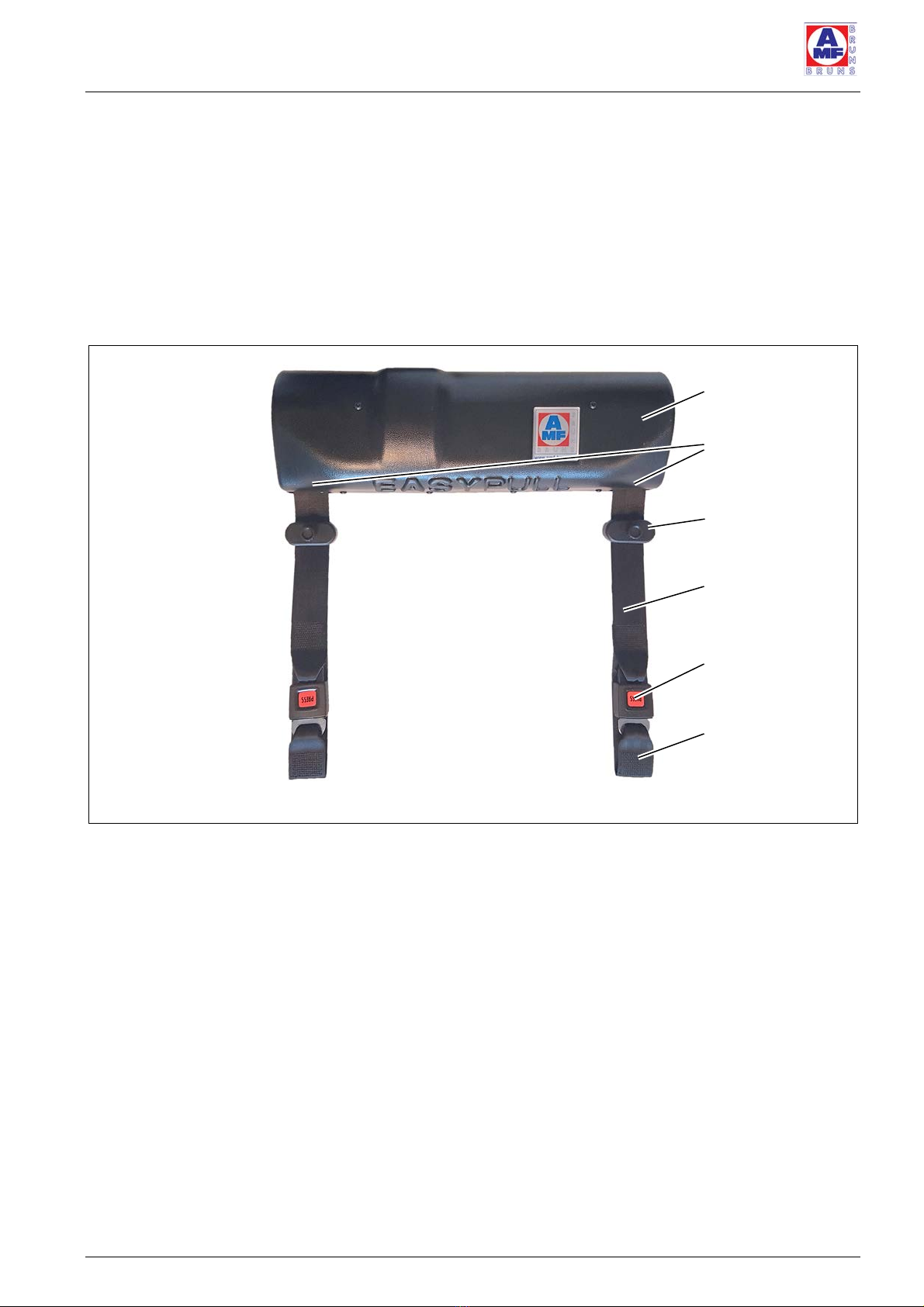
2.1.3 Winch with belts
The winch (see Figure 3) pulls the wheelchair into the vehicle. It com-
prises the winch housing with the motor and interlocks. Two sensors
in the winch housing signal the control unit when the adjustable mag-
nets on the belts are in their proximity. As soon as at least one of the
magnets is in the proximity of a sensor, the winch stops and the belts
are latched in position. Each belt is equipped with a belt lock and a
loop to attach it to the wheelchair.
Figure 3
:
Winch with Belts
Winch housing
Sensors
Magnet
Belt lock
Loop
Belt
Description
Page 14 of 48 EasyPull
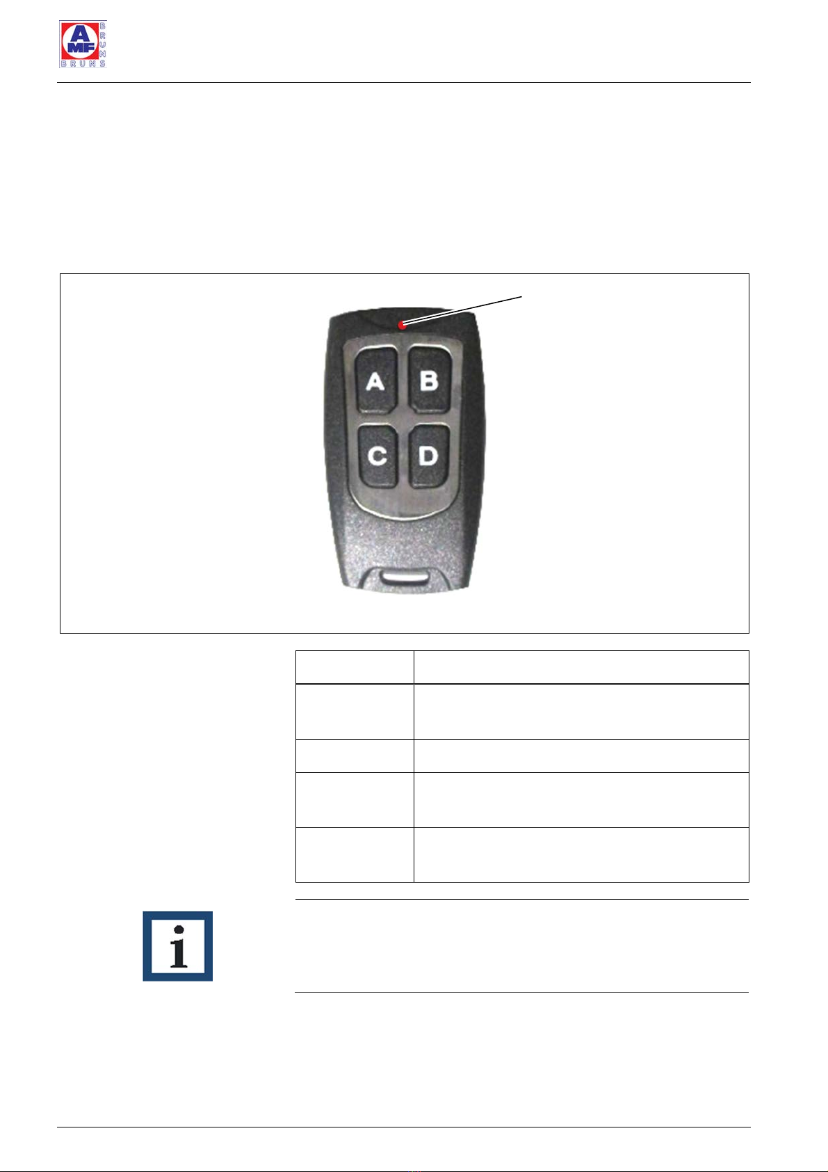
2.1.4 Remote control
The push-buttons on the remote control are used to control the Easy-
Pull functions.
The red LED blinks whenever a push-button is pressed.
If the LED blinks without a push-button having been pressed, the bat-
tery must be replaced (see Section 9.1, page 40).
Figure 4: Remote Control
Push-button Function
A Reels the belts out slowly, in order to pull
the wheelchair out of the vehicle.
B Reels the belts in.
C Reels the belts out quickly, in order to pull
the belts out of the vehicle.
D Resets the control unit in case of a fault
(press button D for at least 15 seconds).
NOTE
The belts are not driven when they are reeled out. The belts reel out
slowly or quickly by braking the winch to a greater or lesser extent. I
f
necessary, the operator must pull the wheelchair out of the vehicle.
LED
Description
EasyPull Page 15 of 48
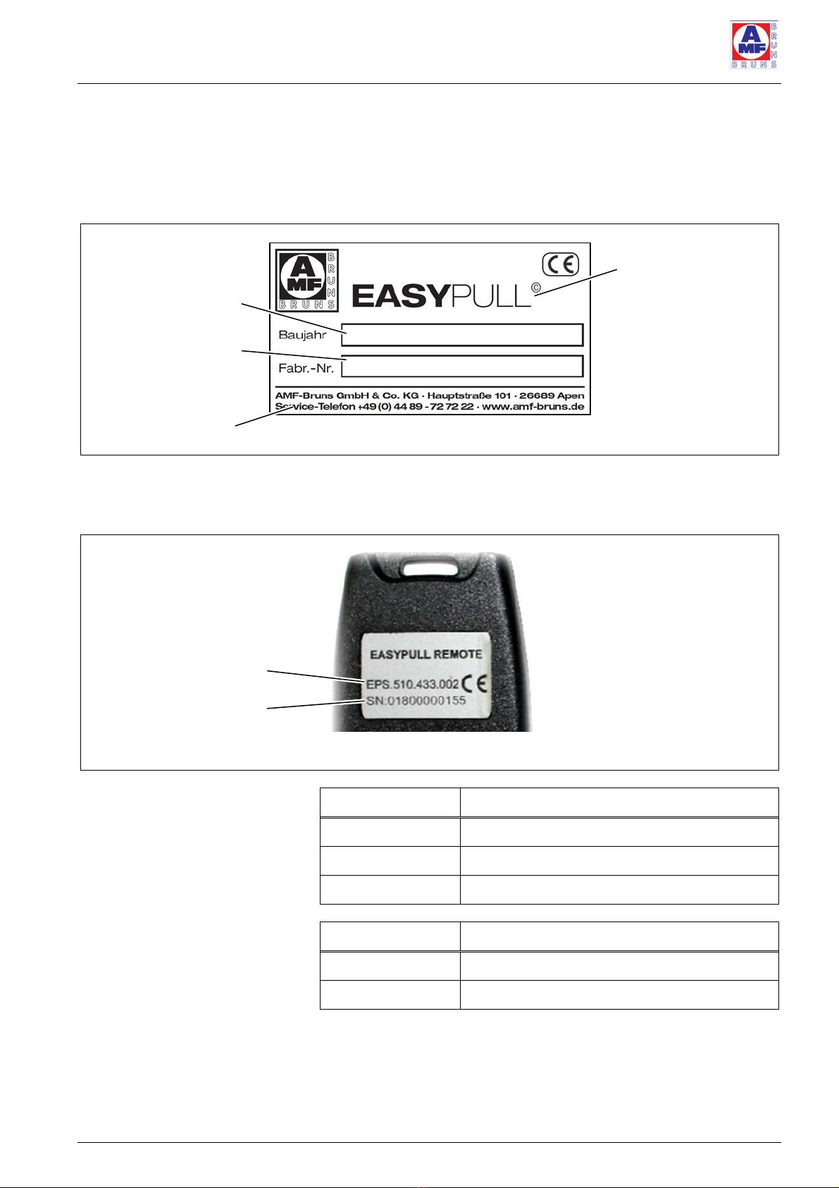
2.1.5 Rating plates
A rating plate, which contains the fundamental data, is attached to
the EasyPull (see Figure 5). The rating plate is located on the EasyPull
baseplate.
Figure 5
:
EasyPull Rating Plate
The remote control’s rating plate is attached to the rear of the remote
control (see Figure 6). It contains the type and serial numbers.
Figure 6
:
Remote Control Rating Plate
Type number Meaning
EPS.510 Hardware type number
433 Frequency
002 Modification state (downwards compatible)
Serial number Meaning
018 Year of production
00000155 consecutive number
Designation
Serial number
Year of manu-
facture
Manufacturer’s
details
Serial number
Type number
Transportation
Page 16 of 48 EasyPull
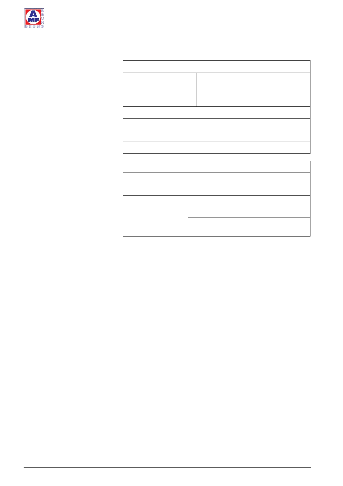
2.2 Technical Data
Designation EasyPull
Dimensions: Width 520 mm
Depth 158 mm
Height 110 mm
Connection voltage 12 V DC
Weight approx. 16 kg
Current consumption approx. 25 A
Rated pulling power approx. 160 kg
Designation Remote Control
Voltage source Button cell CR2025
Power supply voltage 1.8 to 3.3 V DC
Quiescent current < 10 nA
Transmission fre-
quencies
Japan 426 MHz
All other regi-
ons
433 MHZ
3 Transportation
The EasyPull is either shipped by the manufacturer or by a logistics
company assigned by the manufacturer.
Installation
EasyPull Page 17 of 48
4 Installation
NOTE
The vehicle manufacturer's body fitting guidelines must be adhered
to when installing the EasyPull.
The installation company itself is responsible for adherence to the sa-
fety regulations when installing the EasyPull.
Installation is insofar carried out at the sole risk of the installation com-
pany. The manufacturer will accept no liability whatsoever for damage
caused during installation of the EasyPull. Unless such damage is
caused by gross negligence or wilful violation of the contract on the
part of the manufacturer.
In addition to the information given in these Installation Instructions,
local legislative regulations must be taken into consideration, in parti-
cular those regarding safety and accident prevention.
The EasyPull must only be installed in vehicles with a 12 V DC electrical
system.
4.1 Safety Information for Installation
DANGER!
Danger through incorrect installation.
A
number of risks of personal injury and material damage can be
caused if the EasyPull is incorrectly installed in the vehicle.
Such risks can not only occur during installation but also as a result o
f
installation not being carried out correctly.
Therefore:
y The EasyPull must only be installed in the vehicle by trained, spe-
cialist personnel.
DANGER!
Danger through screws becoming loose.
If screws / bolts are not tightened to the specified torque, they can
become loose during operation of the EasyPull. This can result in ac-
cidents being caused.
Therefore:
y Tighten all fastening screws / bolts to the torque specified in Sec-
tion 4.4, page 24.
y If any of the vehicle's original screws are loosened or removed for
installation of the EasyPull, they must be re-
t
ightened to the torque
specified by the vehicle manufacturer.

Installation
Page 18 of 48 EasyPull
DANGER!
Danger through incorrect installation of the power supply cable.
If the power supply cable is not installed correctly, there is a risk o
f
f
ire. This can result in cause serious injuries to the passengers in the
v
ehicle and material damage.
Therefore:
y Secure the cables adequately, such that they will not chafe at an
y
point.
y Do not secure cables to the brake lines.
A
TTENTION!
Risk of material damage.
The control unit can suffer damage when connecting or disconnecting
the starter battery or the power supply cable to the voltage transfor-
mer or control uni
t
, if the door contact switch is not activated at this
point in time.
Therefore:
y Close the rear doors / tailgate of the vehicle before you connect or
disconnect the starter battery.
y Always disconnect the starter battery before carrying out any wor
k
on the EasyPull's electrical system.
4.2 Fitting the Winch
DANGER!
Danger through not adequately securing the winch to the vehicle
chassis.
If the winch is not adequately bolted to the vehicle chassis, accidents
can occur during operation because the fastenings cannot withstand
the loads imposed upon them.
Therefore:
y Always fasten the winch to the vehicle chassis by using all 4 faste-
ning points.
NOTE
The vehicle manufacturer's body fitting guidelines must be adhered
to when installing the winch.
The fastening holes that will be drilled later, must be positioned such
t
hat a positive, metal to metal connection to the vehicle’s chassis can
be made.
The fastening holes must not be positioned above cavities, beams,
seams or similar parts. This must be ensured by the position of the
EasyPull on the vehicle's floor. Otherwise the EasyPull cannot be bol-
ted down correctly.
Remove the winch housing (see Figure 3, page 13).
Place the winch in the position where it is to be installed.

Installation
EasyPull Page 19 of 48
Inspect the underside of the vehicle, to check whether the position
in which the EasyPull is to be installed is suitable to bolt it to the
floor of the vehicle and make a connection to the vehicle’s chassis.
Correct the position of the EasyPull if necessary.
Mark the position of the four fastening holes.
Drill the Ø = 10.5 mm fastening holes.
Check once again that the position of the fastening holes for the
EasyPull is suitable.
Deburr the holes.
Remove all drilling swarf, e. g. using a vacuum cleaner.
Remove underseal from the underside of the vehicle, at the points
to which the EasyPull will be secured.
Apply rust-proofing paint to all bare metal surfaces.
Allow the corrosion protection to dry.
Bolt the EasyPull to the vehicle’s floor and chassis.
Tighten the bolts to the torque specified in Section 4.4, page 24.
4.3 Installing and Connecting the Electrical
System
The electrical system must be connected in accordance with the
electrical circuit diagram (see Chapter 11, page 44).
4.3.1 Fitting the voltage transformer
Disconnect the cable from the negative pole of the starter battery.
Fit the voltage transformer (see Figure 7, page 20).
Connect the red 12 V cable to the positive pole of the starter bat-
tery via the fuse provided.
Fit the fuse holder, including the fuse, in the vicinity of the starter
battery.
Connect the black 12 V cable to an earth connection, e.g. the bo-
dywork or chassis.

Installation
Page 20 of 48 EasyPull
Figure 7
:
Voltage Transformer, Complete
4.3.2 Fitting the control unit
Fit the control unit behind one of the side claddings at the rear of
the vehicle (see Figure 8).
Figure 8
:
Control unit
NOTE
The position in which the control unit is fitted must be close enough
to the winch that the winch can be connected to it using the connec-
tion cable provided on the control unit.
12 V cable
Voltage Transformer
24 V connection
Antenna
Green LED
Red LED
Other manuals for EasyPull
4
Table of contents
Other AMF-BRUNS Automobile Accessories manuals


