HKS 70020-AT115 User manual

1
取説品番 E04521-T25020-00 2017/1/10 作成 Ver.3-1.01 ( 禁無断複写、転載 ) ( 株 ) エッチ・ケー・エス
○適合車輌の年式は 2017 年 1 月現在までのものです。
2017 年 1 月以降に登録された車輌への適合については、お買上の販売店までお問い合わせください。
本書では下記のような記号を使用し、お客様及び作業者への危険レベルを示しています。
作業者又は使用者が傷害を負う危険が想定される場合(人損)
拡大物損の発生が想定される場合
(拡大物損とは、当該製造物が原因で誘発された物的損害[例えば、車輌破損及び焼損])
作業者又は使用者が死亡、又は重傷を負う可能性がある場合
この度は HKS レーシングサクションリローデッドをお買い上げいただき誠にありがとうございます。取付けは必ず専門業者に
依頼し、取付け終了後は本書に記載されている内容を守り安全にご使用ください。
本書は取付けを行う前に必ずお読みください。
●本書は本製品を安全に取付けていただき、あなたや他の人々への危険や損害を未然に防止するために守っていただきたい注意
事項を記載しています。
●お客様又は第三者が本製品及び付属品を誤使用したことにより受けた損害については、当社では一切その責任を負いかねます
のであらかじめご了承ください。
●本製品を使用して生じた損害や、脱着工賃およびそれに付随する費用、また、自動車を使用することができないことによる損
失等につきましては、一切の補償はいたしかねます。
●本製品はノーマル車輌を基準に製作されております。ノーマル車輌以外に取付けた場合は、本製品の機能・性能及び安全性に
ついて保証いたしかねます。
●本製品は日本国内での使用を目的に設計されたものです。海外では使用しないでください。
This product is designed for use in Japan only.It must not be used in any other country.
●本製品の仕様は付属品を含め、改良のため予告なく変更をすることがあります。
●本書は予告なく改版することがありますので本製品と本書の整合をご確認ください。
●消耗部品や紛失部品及び本書のご注文はお買上の販売店までお問い合わせください。部品を発注する際は、商品名・コード No.・
車輌型式・エンジン型式を注文先にお伝えください。
取付けは必ず専門業者に依頼してください。本書はご使用前に必ずお読みください。
本製品は、下記に示す車輌のみ取付可能です。
70020−AT115
①,② FA20D
① 2012 年 4 月〜 , ② 2012 年 3 月〜
トヨタ ① 86 DBA-ZN6
スバル ② BRZ DBA-ZC6
商品名
コード No.
メーカー・車種
エンジン型式
年 式
備 考
レーシングサクション
自動車部品
○ HKS レーシングサクションは、自動車エンジン用エアクリーナー装置です。
スーパーパワーフローフィルターの性能を維持するため、フィルターを定期的に交換してください。
用 途

2
●本製品装着によりエンジン出力が向上しますので、高熱価タイプのスパークプラグへの交換を推奨します。
特に、スポーツ走行等高負荷を多用する場合には、必ず交換してください。
●本製品はノーマル車輌を基準に製作されておりますが、車輌個々の特性によりエアフロメータ出力補正装置
(AFR など ) や、燃料制御装置 (F-CON など ) を用いた燃料セッティングが必要になる場合もあります。
●エアフロメータセンサの吸気温センサが汚れている場合 ( 黒ずんでいてツヤが無い状態 ) は、エアフロメータセンサのセンサ
部も汚れていると考えられるので、パーツクリーナ等を用いてセンサ部を洗浄するようにしてください。
エアフロメータのセンサ部は、外から見えにくい位置にあります。
●電気ショートによる電装部品の破損及び焼損・火災を防止するために,次のことを守ってください。
・バッテリのマイナス端子のターミナルを取外してから作業を行ってください。
・コネクタを外すときは、断線しないようにコネクタを持って外してください。
●本製品の誤使用は絶対に行わないでください。
・誤使用したことにより、最悪の場合エンジンが壊れる恐れがあります。
・本来の性能を損なう恐れがあります。
●作業を始める前にエンジンルーム内の温度が約 40℃位 ( 手で触れて熱くない程度 ) に下がっていることを確認してください。
・火傷する恐れがあります。
●パイプ等に異物が入らないようにウエス等をかけておいてください。
・異物がエンジンに入りエンジンが破損する恐れがあります。
●キットの構成部品をパーツリストに記載してあります。取付け前に異品、欠品の無いことを確認してください。
●ノーマルパーツの取付け取外しはメーカー発行の整備書をよく読んでから行ってください。整備書がお手元にない場合は、
メーカーにてご購入ください。
●本製品の取扱いは慎重に行ってください。落としたり、強いショックを与えないでください。取付け不良や故障の原因になり
ます。
●ボルト、ナット類は適切な工具で確実に締付けてください。必要以上に締付けを行うと、ボルトのねじ部が破損します。
●取付け作業のため、一時的に取外すノーマルパーツは破損又は紛失しないように保管してください。
又、ノーマルパーツを取付ける際は、間違えて取付けないように取外す部品にはマーキングしてください。
●パワーフロー本体のフィルターの交換は定期的に行なってください。
( 交換の目安 )3,000 〜 5,000km または 3 ヶ月〜 6 ヶ月
交換フィルターは別売りです。 品名:スーパーパワーフロー交換用フィルター(φ200)
※洗浄でのメンテナンスは集塵効果が低下しますので絶対に洗浄しないでください。
・但し、使用方法及び環境により条件が異なりますので、汚れ具合によっては上記サイクルより更に早めの交換 ・ 清掃をお勧め
します。
※上記のメンテナンスを怠ると、本製品の性能が維持できないばかりか、車輌のエアフロメータセンサのセンサ部分が汚れて
吸入空気量を正確に検知できなくなり、エンジン不調、破損を引き起こす恐れがあります。
(1) エンジン停止時にエアフロメータを車輌より取外してください。なお、エンジン停止直後はエアフロメータのセンサ部が熱
をもっています。センサ部の破損防止のため、しばらく (5 分以上 ) 冷ましてから作業して下さい。
(2) エアフロメータのセンサ部に向かって速乾性のパーツクリーナを 5 〜 10 秒程吹きつけてください。( センサ破損防止のためエ
アフロメータより 1cm 以上離して吹きつけてください )
(3) すぐにエアを 5 〜 10 秒程吹きつけて、汚れ及びパーツクリーナを取除いてください。( センサ破損防止のためエアフロメータ
より 10cm 以上離して吹きつけてください )
(4) 5 分以上放置して完全にエアフロメータが乾いたら車輌に取り付けてください。
洗浄方法

3RS_AT115_3-1.01
1.ノーマルパーツ取外し
図2
(4) エアフロメータセンサからコネクタを外してください。
(図2)
(5) ボルトを外し、レゾネータとエアクリーナケースとエアフ
ロメータセンサを一体で取外してください。(図2)
レゾネータ
(1) バッテリのマイナス端子(−)からケーブルターミナルを
取外してください。
(2) サクションホースからブローバイホースとサウンドクリ
エーターパイプを取外してください。(図1)
(3) ホースバンドを緩め、サクションホースを取外してくださ
い。(図1)
図1
エアクリーナケース
ブローバイホース
サウンドクリエーター
パイプ
サクションホース
エアフロメータ
センサ
エアクリーナケース
図3
サウンドクリエーター
パイプ
ホース
サウンドクリエーター
(6) ボルトを外し、サウンドクリエーターパイプとサウンドク
リエーターを取外してください。(図3)
ホースを取外す必要はありません。
(7) エアクリーナケースからエアフロメータセンサを取外して
ください。(図2)

2.キットパーツ取付け
4
図4
ホース
プラグ φ 20
(1) 純正ホースにプラグ φ20 を取付け、適当な箇所にタイラッ
プで固定してください。(図4)
A部
B部
図5
A部
25
図6
18
(2) ヘッドルーバーを取付けてください。
(図5、図6、図7)
B部
26
G-1
24
12
11
10
12
11
10
G-2
図7
10. キャップボルト M8-15
11. ウェーブワッシャ M8
12. フランジナット M8
18. ゴムブッシュ
24. ヘッドルーバー
25. ヘッドルーバーステー No.1
26. ヘッドルーバーステー No.2
G-1. ボルト(純正・A部)
G-2. ボルト(純正・B部)

5RS_AT115_3-1.01
図8
(3) ヒートインシュレーターA、B、ヒートインシュレーターステー No.1、No.2 を仮付けしてください。(図8、図10)
ヒートインシュレーターA ヒートインシュレーターB
ヒートインシュレーターステー No.1
ヒートインシュレーターステー No.2
ヒートインシュレーター
ヒートインシュレーター
ステー
ボルト M6-15
スプリングワッシャ M6
プレーンワッシャ M6
フランジナット M6
(4) ヒートインシュレーターを仮付けしてください。(図8、図9、図10、図11)
図9
E部
D部
D部
C部
図 11
図 10
C部
D部
E部
スポンジは適当な長さに切って使用してください。
(5) 位置が決まったらボルト類を本締めし、固定してくださ
い。
13. ボルト M6-20
14. ボルト M6-15
15. スプリングワッシャ M6
16. プレーンワッシャ M6
17. フランジナット M6
18. ゴムブッシュ
27. ヒートインシュレーターA
28. ヒートインシュレーターB
29. ヒートインシュレーターステー No.1
31. ヒートインシュレーターステー No.3
32. ヒートインシュレーターステー No.4
33. スポンジ
G-3. ボルト(純正・D部) 18
17
16
15
13
29
27
31
28
14 16
15 14 16
15
18
16
15
13
33
32
G-3
17

(6) サクションパイプにエルボーとホースニップルφ 12 を取付
けてください。取付ける際は、ネジ部に市販のシールテー
プ等を巻くなどしてエア漏れしないようにしてください。
(図12)
エルボー、ホースニップルは手で締め込んだ後、適切な工
具を用いてさらに 1 〜 2 回転締め込んでください。
(座面が接地するまで締め込む必要はありません)
(7) エアフロメータセンサのOリング(純正)がサクションパ
イプに噛み込まないようにしながら、キットパーツのM4
ビスを使用して取付けてください。この時ビスを締めすぎ
ないようにしてください。
( 締付けトルク 2.0 〜 3.0N・m{0.2 〜 0.3kg・m})(図16)
エルボー、ホースニップルを取付ける際は、ネ
ジ部に市販のシールテープ等を巻くなどしてエ
ア漏れしないようにしてください。
ホースニップルφ 12
サクションパイプ
図 12
エルボー、ホースニップルは手で締め込んだ後、
適切な工具を用いてさらに 1 〜 2 回転締め込んで
ください。
(座面が接地するまで締め込む必要はありません)
(8) パワーフロー本体にジョイントホースφ 80 を取付けてくだ
さい。(図13、図16)
(9) エアガイドの向きを確認し、ジョイントホース内に押し込
んでください。(図13)
その際、パワーフロー本体とエアガイドとの間に隙間を開
けないようにしてください。
パワーフロー本体 ジョイントホース φ 80
エアガイド
ここに隙間を開けないよう
にしてください。 図 13
エンジン不調・破損の恐れがありますので、エアフロメータセンサ、パワーフロー本体、
エアガイドは正確に装着してください。
パワーフロー本体・エアガイド・サクションパイプをぴったりくっつけて隙間を開けないように組み付けて
ください。
6
エルボー

(10) 純正オルタネータ取付けボルトをゆるめ、エアクリーナステーをF部に挟み込む様に仮付けしてください。
(図14、図15、図16)
図 14
F部
ブローバイホース
(11) キットパーツを仮付けしてください。(図14、図16、図17)
エアガイドとサクションパイプとの間に隙間を開けないようにしてください。
図 15
F部
エアクリーナステー
1. パワーフロー本体
2. エアガイド
3. サクションパイプ
4. ジョイントホース φ 80
5. ジョイントホース φ 75
6. エアクリーナステー
7. 汎用ステー
8. ホースバンド #56
9. ホースバンド #48
14. ボルト M6-15
15. スプリングワッシャ M6
16. プレーンワッシャ M6
17. フランジナット M6
19. ビス M4-12
20. カラー M4
G-4. エアフロメータセンサ(純正)
G-5. ブローバイホース(純正)
G-6. オルタネータ取付けボルト(純正)
G-4
G-5
G-6
1
6
2
3
9
7
8
5
4
9
F部
16
17
19
14
20
15
919
20
図 16
7RS_AT115_3-1.01
スロットルへ

1. 汎用ステーをジョイントホースにあてがう。
2. ホースバンドで汎用ステーとジョイントホースを
共締めする。 図 17
装着図
(12) パワーフロー本体がボディなどと干渉しないように位置を
決めてください。位置が決まったら、ホースバンド・ボル
トを固定してください。この時ホースバンド・ボルトを締
めすぎないようにしてください。
パワーフロー本体のホースバンドを締める際は、工具の選
択により締めすぎを回避できる場合があります。
( ドライバー系がおすすめです。ボックスレンチは力が入り
すぎるためなるべく使用しないでください。やむを得ず使用
する場合は力を加減して締めてください。)
締めすぎるとパワーフロー本体が変形または破損する場合が
あります。(締付けトルク:2.0 〜 3.0N・m { 0.2 〜 0.3 kg・m })
図 18
(13) エアフロメータセンサにコネクタを接続してください。
(14) バッテリのマイナス端子(−)にケーブルターミナルを取
付けてください。
パイプ・ホース等の配管が間違っていないか.
バッテリのマイナス端子にケーブルターミナル
が確実に取付けられているか.
ホースバンドが確実に締まっているか.
ボルト・ナット類の締め忘れはないか.
取付けた部品が他の部品と干渉していないか.
エンジン始動前の確認 エンジン始動後の確認
確認項目 確認
各部からエア漏れがないか.
軽く 2,3 度空吹かしを行ないスムーズにエンジン回転
が上がるか.
部品による干渉音はないか.
アイドリング状態に異常はないか.
エンジンを停止し、ボルトが緩んでいないか.
( 再度取付部の締付け確認 )
確認項目 確認
8

快適に運転していただくために、お車を運転する前には必ず日常点検を行ってください。
●安全な整備はドライバーの責任です。必ず実施してください。
●ユーザーマニュアルに記載されている事項以外は専門業者に依頼してください。
●スーパーパワーフローフィルターの性能を維持するため、フィルターの交換は定期的に行ってください。
( 交換の目安 ) 3,000 〜 5,000km または3ヶ月〜6ヶ月
但し、使用方法及び環境により条件が異なりますので汚れ具合によっては早めの交換をおすすめします。
交換フィルターは別売りです。
品名 スーパーパワーフロー φ200交換用フィルター
●故障等の修理はお客様ご自身では絶対に対処せず、必ず専門業者に依頼してください。
●走行中、異音・異臭・振動等の異変があった場合には、ユーザーマニュアルに従って対処してください。
●本製品を譲られる時は、必ず次のオーナーのために取扱説明書をお渡しください。
●本製品をお車から取外す際には、必ず専門業者に依頼してください。
本製品に関するお問い合わせは、専門業者またはお買上の販売店までお問い合わせください。
本書の記載内容は、予告無しに変更することがありますのであらかじめご了承ください。
1パワーフロー
本体
No 品名 数 形状 備考
2
3
4
5
1
1
1
13
No 品名 数 形状 備考
タイラップ
14
15
16
17
5
2
25
No 品名 数 形状 備考
26
27
28
φ 200
-80
1フランジ
ナット M6
7
サクション
パイプ
ジョイント
ホース
エアクリーナ
ステー
エアガイド
φ 75
L=55
φ 80
L=55
ビス M4-12
6 1 18
1
汎用ステー φ80用
ジョイント
ホース
取扱説明書
29
30
ステッカー 1
7 19 31
#56
1
ホースバンド
1
8 20 32
1
ボルト
プレーン
ワッシャ
7
9
9
M6
M6
M6-15
スプリング
ワッシャ
1
ヘッドルーバー
1
ヘッドルーバー
ステー No.1
1
ヘッドルーバー
ステー No.2
キャップ
ボルト 2M8-15
2
9 21 33
10 22 34
11 23 35
12 24 36
#48
3
ホースバンド
フランジ
ナット
2
2
M8
M8
ウェーブ
ワッシャ
ボルト M6-20
ゴムブッシュ 3
2
カラー M4
1
ホース
ニップル φ 12
1
プラグ φ 20
ヒート
インシュレーター
A
1
ヒート
インシュレーター
B
1
ヒート
インシュレーター
ステー No.1
1
ヒート
インシュレーター
ステー No.2
1
ヒート
インシュレーター
ステー No.3
1
ヒート
インシュレーター
ステー No.4
1
スポンジ 1
9RS_AT115_3-1.01
1
エルボー

This manual assumes that you have and know how to use the tools and equipment necessary to safely perform ser-
vice operations on your vehicle. This manual assumes that you are familiar with typical automotive systems and ba-
sic service and repair procedures. Do not attempt to carry out the operations shown in this manual unless these as-
sumptions are correct. Always have access to a factory repair manual. To avoid injury, follow the safety precautions
contained in the factory service manual.
●This manual indicates items you need to pay attention to in order to install this product safely and lists precautions
to avoid any possible damage and/or accidents.
●HKS will not be responsible for any damage caused by incorrect installation and/or use of this product.
●HKS will not be responsible for any labor expenses, related fees or losses incurred during vehicle downtime.
●This product was designed based on installing it onto a factory vehicle. The performance and/or safety cannot be
guaranteed if this product was installed onto other inapplicable vehicles.
● The specications of this product are subject to be changed without notice.
●This manual is subject to be revised without notice.
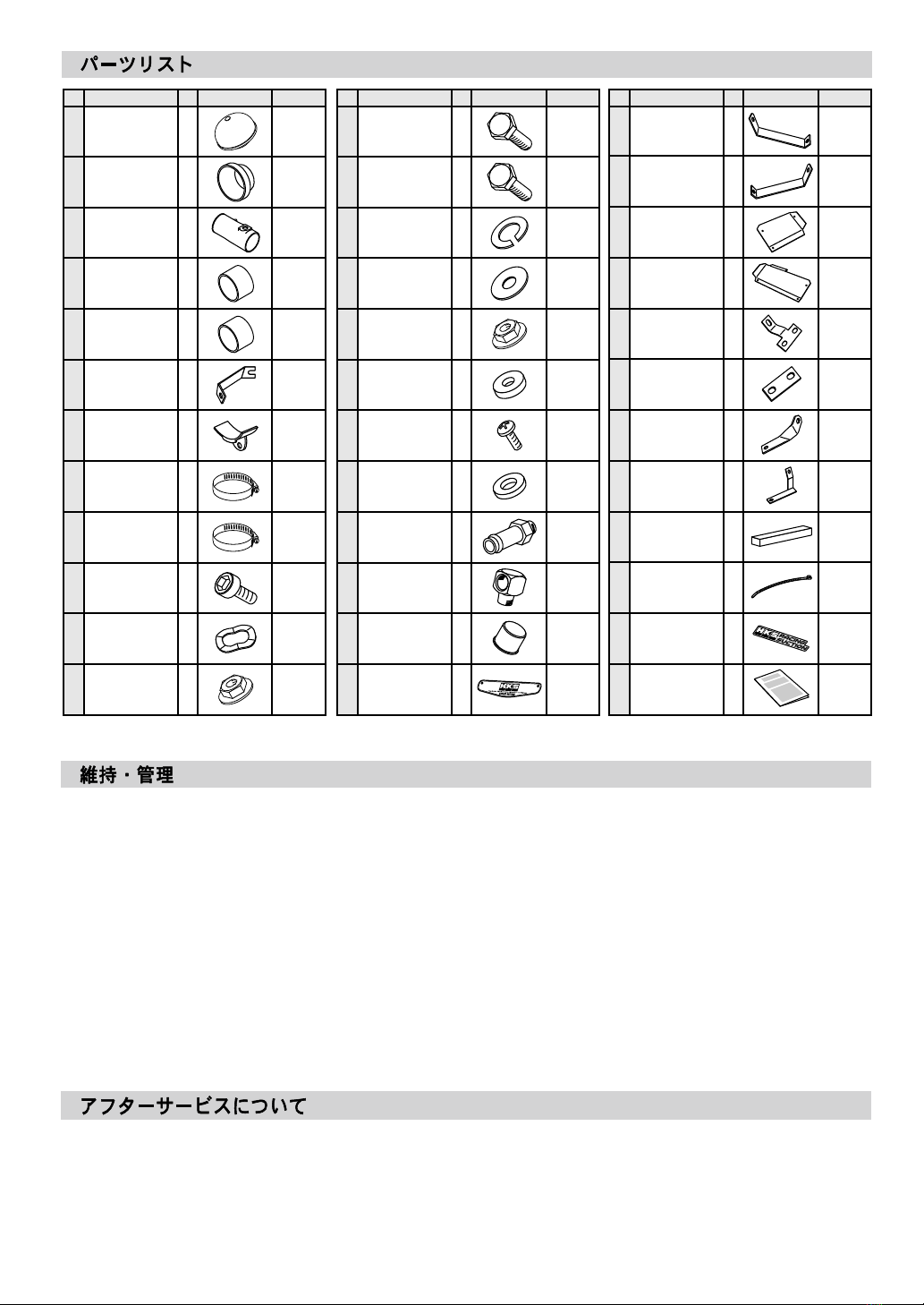
●For any lost parts, consumables or manual, please contact an Authorized HKS Dealer.
SAFETY PRECAUTIONS
WARNING
● To prevent electrical damage/burns/re, always:
- Disconnect the negative terminal of the battery before beginning installation.
- When disconnecting wires/connectors, take extra care to avoid breaking/snapping the connectors.
CAUTION
●Do not misuse this product.
- Misuse of this product may lead to engine damage.
- Misuse of this product may lead to loss of its original function.
●Prior to installation, make sure the engine bay temperature has cooled to approximately 40℃/104°F.
- Failure to let the engine cool down properly can lead to severe burns.
●Insert clean rags into open piping to prevent contaminants from entering the pipes.
- If neglected, contaminants in the piping can lead to engine damage.
10
Published in January, 2017 by HKS Co., Ltd.
(Unauthorized reproduction is strictly prohibited.)
2012 - 2016
TOYOTA 86 ZN6
SUBARU BRZ ZC6
FA20D
ENGINE
YEAR
APPLICATION
PART NUMBER
Racing Suction Intake Kit
70020−AT115
NAME OF PRODUCT

11 RS_AT115_3-1.01
1. REMOVAL OF FACTORY PARTS
ADVICE:
● This product was designed based on and for the factory vehicle; however, additional fuel settings may be necessary
depending on vehicle application.
● If the airow meter intake air temperature sensor is dirty (blackened, no visible shine) it can be assumed that the sensor
itself is also dirty. Using the automotive parts cleaner, carefully clean the sensor.
(1) Disconnect the negative terminal of the vehicle’s battery.
(2) Disconnect the bow-by hose and the sound-creator pipe
from the suction hose. (Dia.1)
(3) Loosen the hose clamp to remove the suction hose. (Dia.1)
- Make sure that all of the parts listed in the Parts List are included in the kit.
- Reference the factory service manual for the vehicle when removing factory parts.
- Be careful when handling this product; avoid dropping or subjecting it to excessive impact. Failure to do so may
result in product damage or improper installation.
- Use the proper tools when tightening nuts and bolts. If over tightened, the bolts may become damaged.
- Keep the removed factory parts in a safe place for ease of re-installation at a later date (if necessary).
When reinstalling the removed factory parts, make sure to reinstall them correctly.
CAUTION
● Replace the air lter element at regular intervals:
(Recommended) Replace every 3,000~5,000km/2,000-3,200miles or every 3~6 months.
Replacement air lter elements are sold separately.
※ Do not wash the air lter elements as the ltration properties will be degraded.
・ There are certain conditions where, depending on dirt buildup, the lter may need to be
cleaned/replaced earlier than the above recommended intervals.
※If the vehicle and the product are not maintained properly as mentioned above, the product may not
perform properly and the airow meter sensor may not be able to detect the intake air volume accurately;
it can lead to engine damage or faulty conditions.

12
(4) Disconnect the airow meter sensor connector. (Dia.2)
(5) Remove the bolt to remove the resonator , the air cleaner
case and the airow meter sensor together. (Dia.2)
(7) Remove the airow meter sensor from the air cleaner case.
(Dia.2)
(6) Remove the bolt to remove the sound-creator pipe and the
sound-creator. (Dia.3)
It is not necessary to remove the hose.

13
2. INSTALLING THE KIT
(1) Insert the 20mm plug to the factory hose, and secure the
hose using tie wraps. (Dia.4)
(2) Install the head louver. (Dia.5, 6, 7)
RS_AT115_3-1.01

14
(3) Temporarily assemble the heat shield panel A , B, heat shield bracket No.1 and No.2. (Dia.8, 10)
(4) Temporarily install the heat shield panel. (Dia.8, 9, 10, 11)
(5) Position the heat shield panel to the vehicle. Once the posi-
tion is determined, secure the heat shield panel to the ve-
hicle using the supplied bolts.

15 RS_AT115_3-1.01
(7) Assemble the airow meter sensor as illustrated in Diagram 16.
Ensure that the factory airow meter sensor’s O-Ring is seated
correctly, making sure it does not get pinched in the suction pipe.
Tighten with the supplied M4 screws.
Do not over-tighten.
Tightening torque: 2.0~3.0 N-m (0.2~0.3 kg-m). (Dia.16)
(8) Install joint hose 80mm to the lter assy. (Dia.13, 16)
(9) Press and insert the air guide into the joint hose. (Dia.13)
Make sure not to leave any gaps between the lter assy
and air guide.
(6) Install the supplied elbow and 12mm hose tting. Wrap the
threaded section with Teon tape to prevent air leakage.
(Dia.12)
ADVICE:
After tightening the hose tting and elbow by hand, tighten it an-
other one to two turns using the appropriate tools. (It is not nec-
essary to tighten the ttings to the point where the nut touches
the pipe.)

16
(11) Temporarily assemble the kit parts. (Dia.14, 16, 17)
Make sure not to leave any space between air guide and suction pipe.
(10) Loosen the factory alternator installation bolt, and temporality install the bracket after inserting the bracket between the
portion "F". (Dia.14, 15, 16)

(12) Position the air cleaner to the vehicle, avoiding
unnecessary contact with other parts of the vehicle. Once
the position is determined, secure the air cleaner to the
vehicle using the supplied hose clamps and bolts.
Do not over-tighten the clamps and bolts.
ADVICE:
Use of proper tools can help avoid over-tightening of hose
clamps. (Screw drivers are recommended. Do not use boxed
wrenches since they tend to use more force.) If over-tight-
ened, the air cleaner may bend or become damaged. (Tight-
ening torque: 2.0~3.0 N-m {0.2~0.3 kg-m})
(13) Reconnect the airow meter sensor connector.
(14) Reconnect the negative terminal to the vehicle’s battery.
Check the following after the installation process is complete.
(1) Check the following before starting the engine:
●Make sure all pipes and hoses are routed and connected correctly.
●Make sure all hose clamps are tightened.
●Make sure the negative cable terminal is securely attached to the battery.
●Make sure all bolts and nuts are tightened.
●Make sure all installed components do not come in contact with other parts.
(2) Start the engine and check the following:
●Make sure air is not leaking.
●Make sure the RPM rises smoothly after revving the engine 2-3 times while in neutral.
●Make sure the installed parts are not hitting each other.
●Make sure there are no issues idling.
●Make sure there are no loose parts after the engine is stopped.
17 RS_AT115_3-1.01

18
Proper daily maintenance of this product is necessary in order to maintain the safety, reliability, and function of this product.
Maintenance is the responsibility of the driver/owner.
- If work needs to be performed outside the scope of this manual, consult a professional.
- If the vehicle becomes damaged, have the repairs performed by a professional.
- If you experience abnormal noises, scents, or vibrations from the vehicle while driving, reference the vehicle’s Owner’s Manual.
- If this product is ever sold, please give this Instruction Manual to the new owner.
- When removing this product from the vehicle, please consult a professional.
1Filter Assy
2
3
4
5
1
1
1
13
Tie Wrap
14
15
16
17
5
2
25
26
27
28
200
-80mm
1Flange Nut M6
7
Suction Pipe
Joint Hose
Bracket
Air Guide
75mm
L=55
80mm
L=55
Screw M4-12
6 1 18
1
Universal
Bracket 80mm
Joint Hose
Instruction
Manual
29
30
Sticker 1
7 19 31
#56
1
Hose Clamp
1
8 20 32
1
Bolt
Flat Washer
7
9
9
M6
M6
M6-15
Lock Washer
1
Head Louver
1
Head Louver
Bracket No.1
1
Head Louver
Bracket No.2
Bolt 2M8-15
2
9 21 33
10 22 34
11 23 35
12 24 36
#48
3
Hose Clamp
Flange Nut
2
2
M8
M8
Wave Washer
Bolt M6-20
Rubber
Bushing 3
2
Collar M4
1
Hose Fitting 12mm
1
Plug 20mm
Heat Shield
Panel A 1
Heat Shield
Panel B 1
Heat Shield
Bracket No.1 1
Heat Shield
Bracket No.2 1
Heat Shield
Bracket No.3 1
Heat Shield
Bracket No.4 1
Sponge Tape 1
No. Description Qty Image Remarks No. Description Qty Image Remarks No. Description Qty Image Remarks
1
Elbow

19 RS_AT115_3-1.01

20
Table of contents
Other HKS Automobile Accessories manuals

HKS
HKS HIPERMAX R User manual

HKS
HKS HIPERMAX R User manual

HKS
HKS 14007-AK006 User manual

HKS
HKS 70019-AF011 User manual

HKS
HKS 12001-AT005 User manual

HKS
HKS VIITS-SS001 User manual

HKS
HKS 48004-KB001 User manual

HKS
HKS Power Editor User manual

HKS
HKS HIPERMAX G+ LIFT UP User manual

HKS
HKS 70018-AT005 User manual