AMF-BRUNS SMARTSTEP ELECTRIC STEP User manual
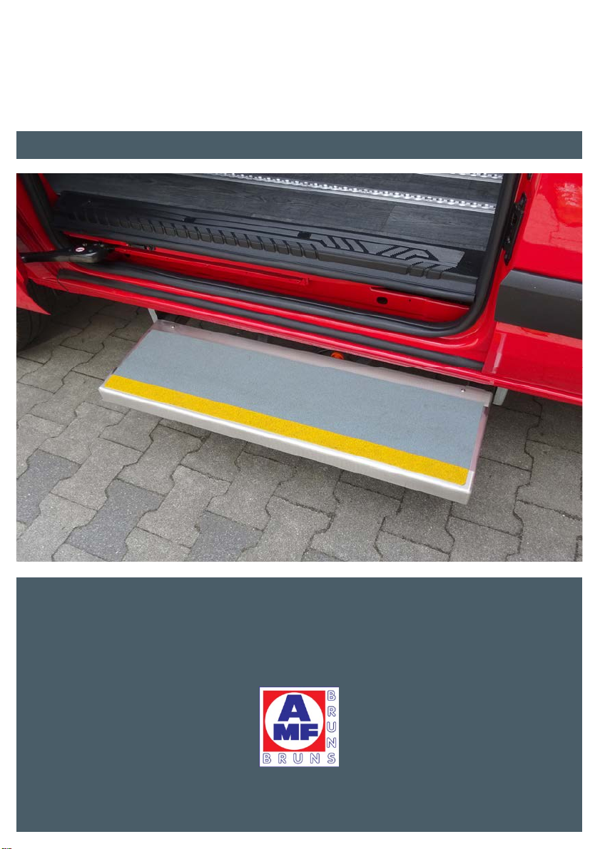
SMARTSTEP ELECTRIC STEP
Operating Instructions
www.amf-bruns.de


Foreword
Smartstep Page 3
Foreword
Dear Reader,
these Operating Instructions serve to provide all information required
for the safe use of the fully-automatic electric Smartstep.
The Smartstep is designed and constructed in accordance with state-
of-the-art technology and recognised safety standards. Persons and
material assets can however still be at risk, as not all danger areas
can be eliminated if the functional capability is to be maintained. Acci-
dents caused by these risks can however be prevented by strictly ob-
serving these Operating Instructions. Over and above this, the opera-
tional efficiency of your Smartstep can be used to the full and unnec-
essary faults can be prevented.
These Operating Instructions only apply to the Smartstep Electric Step
specified on the cover page and in the footnotes. Compare the data
given on the rating plate and the supplementary plate on your electric
step with the images provided in these Operating Instructions (see
Section 2.5, page 17).
After reading these Operating Instructions for the first time, keep them
in a safe place for future reference over the entire lifetime of the Smart-
step Electric Step. If you sell the Smartstep, hand these Operating In-
structions over to the new owner.
Keep these Operating Instructions in the vehicle so that they can be
referred to at any time when problems or questions arise.
All details, figures and dimensions given in these Operating Instruc-
tions are non-binding. They cannot be used as the basis for any claims
whatsoever.
This document must not be reproduced or duplicated, in full or in part,
without the prior, written permission of the manufacturer and the dis-
tribution partner.
The Smartstep must never be converted or modified in any way, with-
out seeking the prior, written permission of the manufacturer and dis-
tribution partner. The manufacturer and distribution partner will not be
held responsible in any way whatsoever if conversions or modifica-
tions are carried out without authorisation.
Foreword
Page 4 Smartstep
Use only original spare parts or spare parts which have been approved
of by the manufacturer or the distribution partner. If spare parts other
than these are used, this can have a negative effect on the specified
characteristics, the functionality and safety of the Smartstep. If other
spare parts are used, liability for consequential damage will be ren-
dered null and void.
Contact our customer service department to order spare parts or ac-
cessories (see Chapter 11, page 45).
NOTE
The current version of these Operating Instructions as well as the cur-
rent versions of supplementar
y
documents (e.
g
. the instructions for
optional equipment) can be found under:
www.amf-bruns-behindertenfahrzeuge.de/service/download-portal/
Explanation of symbols and signs
To improve understanding, the following conventions should be met
for these Operating Instructions:
1.
The following conventions are used to highlight important information:
DANGER
...warns of a situation of immediate dan
g
er, which can cause severe
or fatal injuries if not avoided.
WARNING!
...warns of a potentiall
y
dan
g
erous situation, which can cause severe
or fatal injuries if not avoided.
CAUTION
...warns of a potentiall
y
dan
g
erous situation, which can cause sli
g
ht
injuries, if not avoided

Foreword
Smartstep Page 5
A
TTENTION
...warns of a potentiall
y
dan
g
erous situation, which can cause material
damage, if not avoided.
...contains general notes and useful information.
...gives a reference to important information contained in other sec-
tions and documents.
2.
Some text passages serve a special purpose. These are identified as
follows:
y Lists.
Instructional text, e.g. a sequence of activities.
3.
Meaning of directions:
If directions are given in the text (in front of, front, behind, rear, right,
left), these directions relate to the normal direction of travel of the ve-
hicle.

Contents
Page 6 Smartstep
Contents
1 Safety .................................................................................8
1.1 Proper Use............................................................................ 9
1.2 Improper Use ........................................................................ 9
1.3 User Requirements .............................................................. 10
1.4 Product Monitoring .............................................................. 10
1.5 Danger Zone .........................................................................11
1.6 Safety Devices ......................................................................11
1.6.1 Obstacle detection .....................................................11
1.6.2 Status indicator lamp..................................................11
1.7 Safety and Accident Prevention Regulations ....................... 12
2 Description....................................................................... 14
2.1 Step...................................................................................... 14
2.2 Frame................................................................................... 15
2.3 Drive Unit.............................................................................. 16
2.4 Controller ............................................................................. 17
2.5 Rating Plate .......................................................................... 17
2.6 Operating Controls and Indicators ....................................... 19
2.7 Technical Data ..................................................................... 21
3 Transportation ................................................................ 22
4 Installation and Commissioning ..................................... 23
4.1 Safety Instructions for installation and Commissioning ....... 23
4.2 Recommissioning After Decommissioning.......................... 24
5 Operation ........................................................................ 25
5.1 Safety Regulations for Operation ........................................ 25
5.2 Extending and Retracting the Smartstep ............................ 28
5.3 Restarting After Stopping for an Obstacle .......................... 29
5.4 Switching the Obstacle Detection ON and OFF (optional) .. 30

Contents
Smartstep Page 7
6 Maintenance and Repair.................................................. 31
6.1 Safety Regulations for Maintenance and Repair.................. 31
6.2 Routine Maintenance Work .................................................32
6.2.1 Maintenance schedule..............................................33
6.2.2 Maintenance record..................................................33
6.3 Carrying Out Maintenance Work .........................................34
6.3.1 Cleaning ....................................................................34
6.3.2 Checking the safety devices .....................................35
6.4 Maintenance and Repair Record ......................................... 37
7 Decommissioning and Conservation ............................. 38
8 Disposal........................................................................... 39
9 Faults and Troubleshooting ............................................ 40
9.1 Safety Regulations for Troubleshooting ...............................40
9.2 Troubleshooting Table .........................................................40
9.3 Retracting using the Emergency Mode ...............................42
10 Electrical Circuit Diagram ............................................... 44
11 Customer Service ........................................................... 45

Page 8 Smartstep
Safety
1
2
3
4
5
6
7
8
9
10
11
1 Safety
WARNING
There are a number of risks of sufferin
g
personal injur
y
and material
damage involved in the operation and maintenance of the Smartstep.
Therefore:
y It is imperative, that these Operating Instructions are read thor-
ou
g
hl
y
before operatin
g
the Smartstep. Alwa
y
s observe the notes
and information contained herein, in particular the Safet
y
Instruc-
tions.
y If these Operatin
g
Instructions or parts thereof are lost or become
illegible, please request a new copy from the manufacturer.
For safet
y
information re
g
ardin
g
the basic vehicle, refer to the vehicle
operating instructions.
Prerequisite to the safe handling and trouble-free operation of the
Smartstep is a thorough knowledge of the applicable safety infor-
mation and the safety regulations.
It is therefore imperative that this Chapter is read thoroughly before
operating the Smartstep and that the instructions and warnings herein
are strictly observed. Safety Instructions and warnings that are given
at the corresponding places in the text in the following Chapter must
also be strictly observed. Neither the manufacturer nor the distribution
partner will be held liable if safety information and warnings are not
strictly adhered to.
In addition to the information given in these Operating Instructions, lo-
cal legislative regulations must be taken into consideration, in particu-
lar those regarding safety and accident prevention.

Safet
y
Smartstep Page 9
1
2
3
4
5
6
7
8
9
10
11
1.1 Proper Use
The Smartstep is used to assist persons when embarking or disem-
barking a vehicle. Only one person must stand on the step at any one
time.
Proper use also includes strictly adhering to the information given in
these Operating Instructions.
WARNING!
If the Smartstep is used for any other purpose than that described
above, this ma
y
result in dan
g
erous situations for persons or material
damage being caused.
Therefore:
y Only use the Smartstep for the purpose for which it was intended.
y Always adhere to information given in these Operating Instructions.
y Do not use the Smartstep for an
y
other use, particularl
y
those
g
iven
in Section 1.2. These are deemed to be improper use.
1.2 Improper Use
Any use other than that described in Section 1.1 is deemed to be im-
proper use.
The Smartstep is deemed to be improperly used if for example:
y it is used to support goods when loading or unloading the vehicle,
y it is subject to a load in excess of 250 kg,
y if two persons stand on it at any one time (exception: load test,
see Section 6.2.1, page 33),
y it is used whilst the vehicle is in motion.
y it is used when in a faulty state or with safety-relevant malfunctions,
y when unauthorised modifications have been made to the Smart-
step,
y it is operated by persons who do not fulfil the necessary require-
ments (see Section 1.3, page 10).
Page 10 Smartstep
Safety
1
2
3
4
5
6
7
8
9
10
11
1.3 User Requirements
The Smartstep must only be used and operated by the following per-
sons:
y The person in charge of the vehicle who has read these Operating
Instructions.
y Other persons who have read these Operating Instructions.
y Other persons who have been made aware of the Smartstep and
its function by the person in charge of the vehicle.
Transportation, installation, commissioning, maintenance, repair, fault
finding and disposal of the Smartstep must only be carried out by per-
sons with the corresponding technical training and experience.
1.4 Product Monitoring
Please contact AMF-Bruns GmbH & Co. KG immediately if faults or
problems are encountered when operating the Smartstep or if acci-
dents or "near-misses" occur.
AMF-Bruns will effect a solution to the problem with your help and the
knowledge gained will flow into future projects.
NOTE
Guarantee work on the Smartstep must only be carried out with
t
he
prior agreement of AMF-Bruns GmbH & Co. KG.
The costs of such work will not be accepted by AMF-Bruns without
prior agreement.

Safet
y
Smartstep Page 11
1
2
3
4
5
6
7
8
9
10
11
1.5 Danger Zone
Persons standing within the danger zone are at risk of suffering an
injury or harm their health.
The danger zone is the area in the immediate vicinity of the vehicle
into which the Smartstep retracts. When the Smartstep is being ex-
tended or retracted, the area on Smartstep itself also forms part of
the danger zone.
WARNING
Risk of injury through movements of the Smartstep.
There is a risk of personal injury if standing within the danger zone.
Therefore:
y Keep a safe distance from the vehicle when the Smartstep is bein
g
extended.
y If necessary, make other persons aware that the Smartstep is be-
ing extended.
y Make certain that no person is standin
g
on the Smartstep when it
is being extended or retracted.
1.6 Safety Devices
1.6.1 Obstacle detection
The supply current to the electric motor is monitored by the controller.
If the Smartstep makes contact with an obstacle when it is being ex-
tended, the supply current will increase. This will be detected by the
controller and the Smartstep will come to a standstill.
The risk of injury to persons in the vicinity of the Smartstep, when it is
being extended, is drastically reduced through the obstacle detection
feature
1.6.2 Status indicator lamp
The orange indicator lamp on the dashboard informs the driver of the
status of the Smartstep during normal operation (see Section 2.6,
page 19) and when a malfunction occurs (see Chapter 9, page 40).

Page 12 Smartstep
Safety
1
2
3
4
5
6
7
8
9
10
11
1.7 Safety and Accident Prevention Regu-
lations
Adhere to the following notes in order to prevent personal injuries and
material damage. For commercial use, also adhere also to the relevant
safety and accident prevention regulations laid down by the trade as-
sociations.
y The Smartstep must only be operated if all safety devices are in-
stalled correctly and are fully functional. Safety and protective de-
vices (see Section 1.6, page 11) must only be deactivated or re-
moved in order to carry out maintenance and repair work. All safety
and protective devices must be replaced immediately after such
work has been completed. Otherwise, there is a high risk of injury.
y The Smartstep must only be used for the purpose for which it is
intended, otherwise dangerous situations, with resultant injuries,
can occur (Proper use: see Section 1.1, page 9).
y The owner is responsible for ensuring that proper use is adhered
to, in particular that the Smartstep is only operated by authorised
persons.
y If the Smartstep is used commercially or as a public utility, the
owner must ensure that operating personnel are familiar with the
operation of the Smartstep under all operating conditions by giving
training and familiarisation courses.
y Proper use of the Smartstep also includes adherence to the spec-
ified maintenance and repair work, in particular the strict adher-
ence to the maintenance intervals (see Chapter 6, page 31). If such
work is not carried out, trouble-free operation cannot be guaran-
teed. There is a risk of personal injury and material damage being
caused. We recommend that maintenance a record is kept.
y After installation, the Smartstep must be inspected by a technical
expert. During inspection, faults affecting the safety should be sys-
tematically identified and remedial action taken.

Safet
y
Smartstep Page 13
1
2
3
4
5
6
7
8
9
10
11
y An inspection must also be carried out by a technical expert if mod-
ifications are made to the construction or major repairs are carried
out on load-bearing parts of the Smartstep.
y The Smartstep must never be operated in a faulty condition, as this
can result in serious injuries. If faults occur, do not use the Smart-
step until repairs have been effected (see Chapter 7, page 38).
y Do not place any foreign objects on the Smartstep. Persons can
suffer injuries if such objects fall off the step.
y Switch the vehicle’s engine OFF before carrying out maintenance
or repair work, this includes cleaning work. Secure the vehicle, to
prevent it from rolling away. Render the Smartstep inoperative (see
Chapter 7, page 38). It is not sufficient just to switch OFF the auto-
matic function using the deactivation switch. Take steps to ensure
that the vehicle cannot be started by any other person (e.g. by
removing the ignition key and keeping it in a safe place). If this is
not done, there is a risk of injury.
y Do not repair of bridge defective fuses but replace them with fuses
of the same Ampere rating.
y Do not open the controller. Do not modify electronic components,
particularly those in the controller. This can render safety functions
and protective devices inoperative.
y Use only original spare parts and accessories that have been ap-
proved of by the manufacturer. If other parts are used, liability for
the consequences will be rendered null and void.

Page 14 Smartstep
Description
1
2
3
4
5
6
7
8
9
10
11
2 Description
For a description of the basic vehicle, refer to the vehicle Operatin
g
Instructions.
Persons can embark and disembark a vehicle with the aid of the
Smartstep.
The main components of the Smartstep are:
y the step itself,
y the frame and
y the motor.
The aim of this Chapter is to illustrate the construction and function of
the Smartstep. To this end, the individual assemblies and components
are described in the sections that follow.
2.1 Step
The step is automatically extended when the side door is opened.
When the vehicle is in motion, it is retracted under the vehicle. The
step has a non-slip surface and a high-visibility strip on the leading
edge (see Figure 1 and Figure 2, page 15). The step can be opened
up by removing the cover plate underneath it.
Figure 1: Smartstep, retracted
Step
Frame

Description
Smartstep Page 15
1
2
3
4
5
6
7
8
9
10
11
Figure 2: Smartstep, extended
2.2 Frame
The frame is a steel construction that is bolted to the underside of the
vehicle. It comprised a main frame that is firmly attached to the vehicle
and two telescopic arms that form a flexible connection between the
main frame and the step (see Figure 3).
Figure 3: Frame
Step
Frame
Telescopic
arms
Main frame
Page 16 Smartstep
Description
1
2
3
4
5
6
7
8
9
10
11
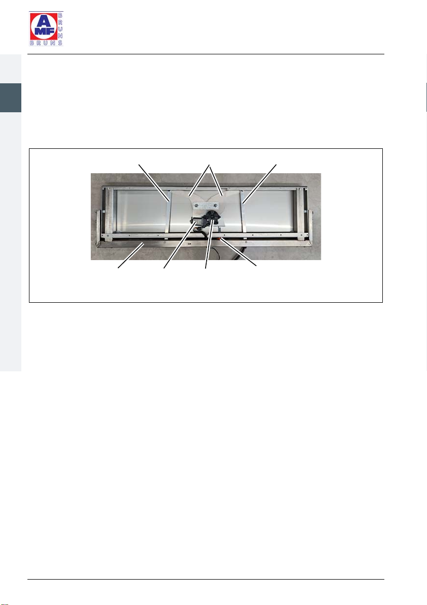
2.3 Drive Unit
The Smartstep drive unit has a 12 V direct current (DC) motor. This
drives the gearing that moves the swivel arms. The swivel arms are
connected to the step by connecting rods. The drive components are
contained within the step‘s housing (see Figure 4).
Figure 4: Drive Unit (step housing cover plate removed)
Gearing
Swivel arm
Motor
Coupling rod Coupling rod
Knurled screw, for decou-
pling in an emergency
Frame

Description
Smartstep Page 17
1
2
3
4
5
6
7
8
9
10
11
2.4 Controller
The controller is connected to the step’s electrical components and
controls movements of the Smartstep as well as the indicator lamp
(see Figure 5). The controller effectively brakes the movement of the
step before it reaches the end limit positions. It includes the obstacle
detection feature and fault diagnostics. The controller is supplied by
the vehicle’s electrical supply and is installed in the interior of the ve-
hicle (normally underneath the passenger seat).
Figure 5: Controller
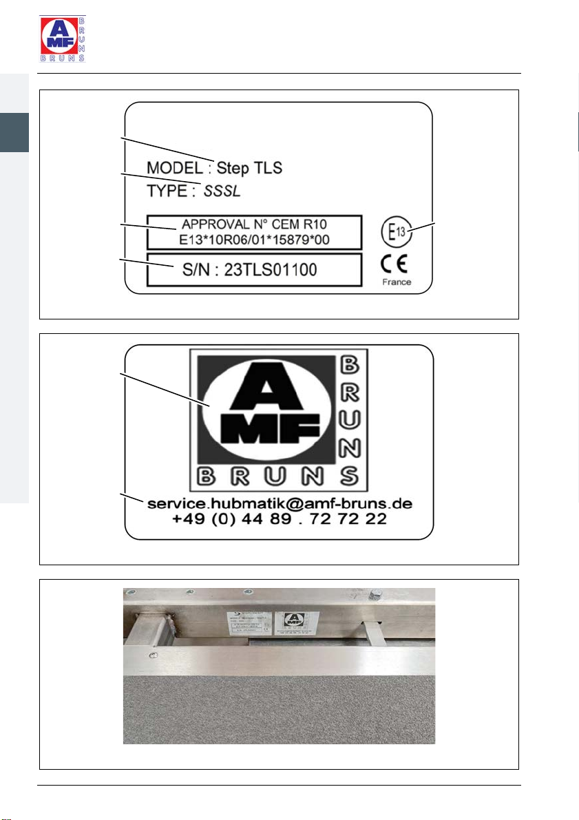
2.5 Rating Plate
A rating plate, containing the fundamental data, is attached to the
Smartstep (see Figure 6, page 18). A supplementary plate shows the
contact details for the distribution partner - AMF-Bruns (see Figure 7,
page 18, detailed contact data: see Chapter 11, page 45). Both the rat-
ing plate and supplementary plate are located on the inside of the main
frame (see Figure 8, page 18).
Page 18 Smartstep
Description
1
2
3
4
5
6
7
8
9
10
11
Figure 6: Rating Plate
Figure 7: Supplementary Plate
Figure 8: Positions of Rating Plate and Supplementary Plate
ECE seal of
approval
Manufacturer’s
model
designation
Manufacturer’s
t
ype
designation
Type
approval
Serial number
Distribution
partne
r
Distribution
partner con-
tact data
Description
Smartstep Page 19
1
2
3
4
5
6
7
8
9
10
11
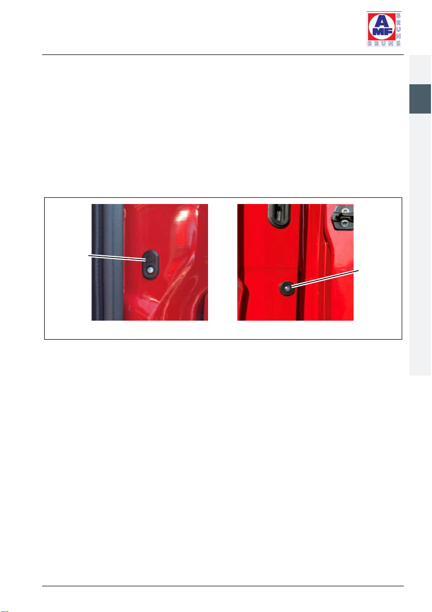
2.6 Operating Controls and Indicators
Door contact switch
The Smartstep is fully automatic and is controlled by a door contact
switch, which is operated by opening and closing the side door imme-
diately above it. The door contact switch is operated magnetically and
is located in the side door pillar. The door contact switch is triggered
by a contact installed in the side door at the same height as the switch
(see Figure 9).
Figure 9: Door Contact Switch and Trigger Contact
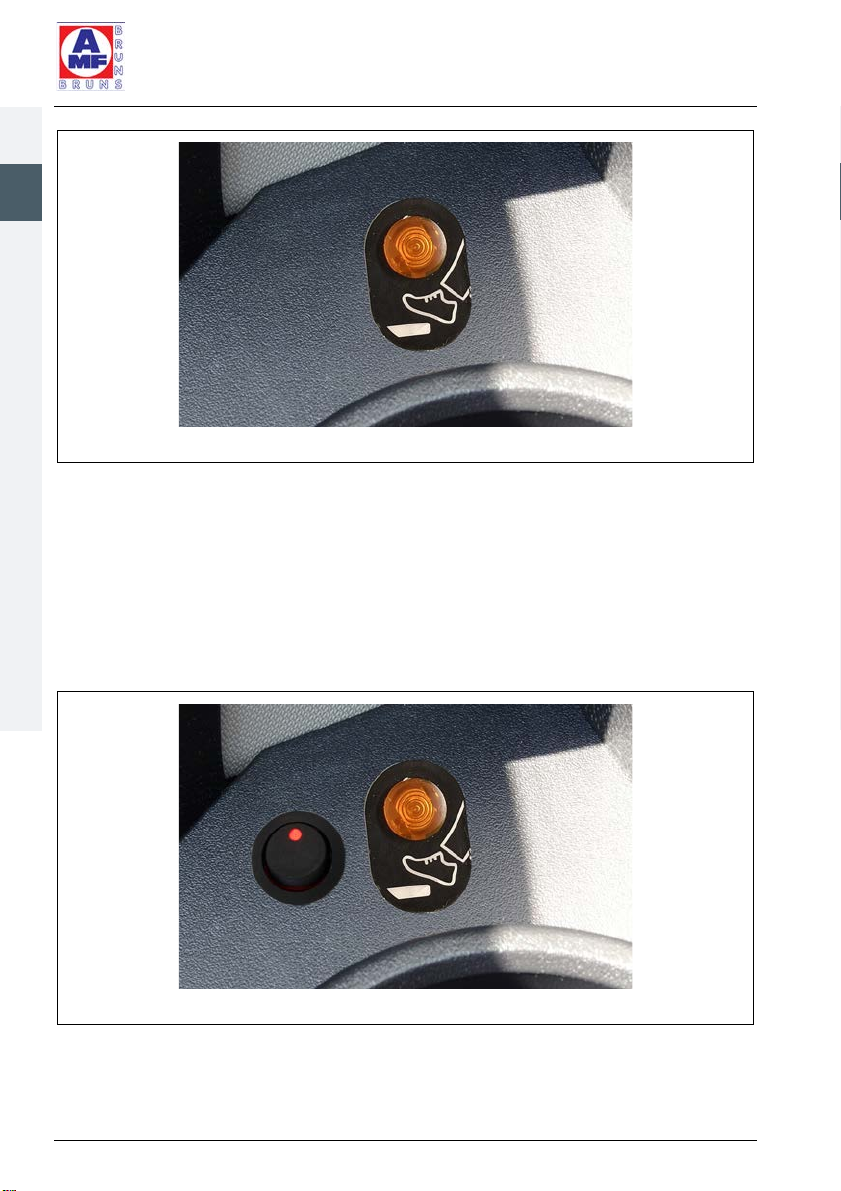
Status indicator lamp
The Smartstep status indicator is an orange LED fitted to the dash-
board. It is identified by a symbol representing a foot on a step (see
Figure 10, page 20). The indicator lamp blinks twice per second when
the step is being extended or retracted. The indicator lamp lights con-
tinuously when the Smartstep is fully extended and does out when the
Smartstep is fully retracted.
The indicator lamp signals faults by blinking (see Chapter 9, page 40).
Door
contact
switch
Trigger
contact
Page 20 Smartstep
Description
1
2
3
4
5
6
7
8
9
10
11
Figure 10: Status indicator lamp
Deactivation switch (optional)
An optional deactivation switch can be installed next to the indicator
lamp. The automatic function of the Smartstep can be switched ON
and OFF by the deactivation switch. If the automatic function is
switched OFF, the Smartstep will not extend when the side door is
opened. The indicator lamp in the deactivation switch lights up when
the automatic function is switched ON.
Figure 11: Deactivation Switch next to the Indicator Lamp
Table of contents
Other AMF-BRUNS Automobile Accessories manuals


