manuals.online logo
Brands
  1. Home
  2. •
  3. Brands
  4. •
  5. JKS
  6. •
  7. Automobile Accessories
  8. •
  9. JKS JKS1610 User manual

JKS JKS1610 User manual

JKS1610JKS Control Arm Installation Page 1
INSTALLATION
INSTRUCTIONS
Product: Front Adjustable Lower Control Arms
Part Number: JKS1610
Applications: Wrangler JK, 2007+ (front only)
Welcome
CONGRATULATIONS on purchasing a set of new Con-
trol Arms from JKS Manufacturing. We are committed to
providing you with the best products available and your
satisfaction is our rst priority.
PLEASE READ these Installation Instructions carefully,
and save them for future reference, as they contain impor-
tant installation and maintenance information.
Important
SUSPENSION COMPONENTS THAT HAVE RUBBER
BUSHINGS must be tightened with vehicle on level
ground and at normal ride height. The springs must
be supporting weight of vehicle when the hardware is
torqued.
RUBBER BUSHINGS MUST NEVER BE LUBRICATED,
as doing so will impair performance and longevity.
COMPATIBLE WITH original 4-link suspension con-
guration and vehicle ride height up to 4.5”.
REFER TO FACTORY SERVICE MANUAL for informa-
tion and procedures not covered in these instructions.
ATTENTION INSTALLER
Install Control Arms ONE AT A TIME for easiest alignment
of mounting hardware.
Tools Required
JKS1695 or equivalent jam nut wrench
Hydraulic Floor Jack and Jack Stands
Metric/Standard Socket Wrench Set
Torque Wrench
Anti-Seize Lubricant
Heavy Duty Ratchet Strap *
Factory Service Manual (recommended)
* Asterisk denotes tools that are not required for some applica-
tions. Thoroughly read instructions rst to determine which tools
will be required for your application.
Installation
1. REMOVE ORIGINAL LOWER
SUSPENSION ARM
Raise and support the vehicle chassis with jack
stands positioned in rear of the front lower suspen-
sion arm brackets.
Raise the front axle housing back into position
and support with a hydraulic jack. HINT: The
axle housing should be evenly supported and the
suspension at normal ride height. Do not attempt
removal or installation with the suspension extend-
ed, or the axle drooped, as this will place tension
on suspension arm mounting hardware.
Remove the lower suspension arm bolt and nut
from the axle housing bracket. Retain the original
mounting hardware.
Remove the bolt and nut from the chassis rail
bracket. Retain the original mounting hardware.
517-278-1226 • [email protected] • www.jksmfg.com
491 W. Gareld Avenue, Coldwater, MI 49036
JKS1610 JKS Control Arm Installation
2 Page
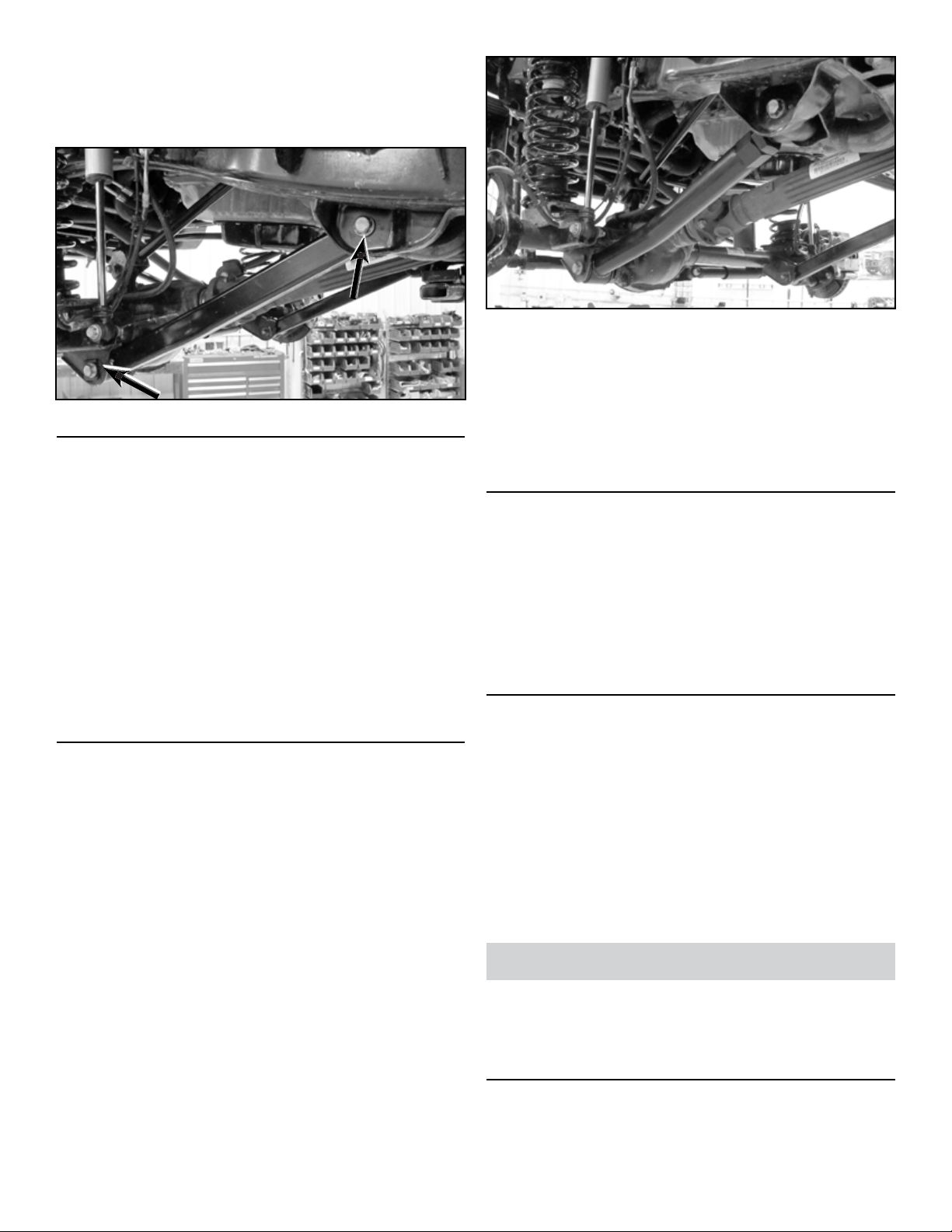
Remove the original lower suspension arm from
the vehicle.
Proceed to step 2. Complete installation on one
side before starting other side.
2. SET CONTROL ARM LENGTH
Determine the ideal arm length for your application
by considering factors such as:
ÂTire Clearance
ÂSteering Clearance
ÂPinion Angle / Caster
ÂFactory length is 22-5/8"
ÂMax. length is 24 3/8"
Set both control arms to the same length.
Lengthening the arms will increase caster and
reduce pinion angle.
3. INSTALL CONTROL ARM
Apply anti-seize lubricant to bolt threads of original
mounting hardware.
Establish control arm orientation. The arms
should be mounted so that the bend goes inward
(away from the tire) and the rubber bushing end
mounts to the axle.
Mount the control arm to the axle housing bracket.
Install the original mounting bolt and nger tighten
the nut. DO NOT torque mounting hardware until
instructed.
Mount the control arm to the frame rail bracket so
the grease tting is up on the ex eye. Install the
original mounting bolt and nut. Finger tighten the
bolt.
HINT: If mounting bolt is difcult to install due to misalign-
ment of Control Arm bushing with mounting bracket, either
(1) adjust height of axle housing with hydraulic jack, (2)
move axle housing into position with a heavy-duty ratchet
strap, or (3) temporarily disconnect track bar until mounting
holes align.
4. TIGHTEN MOUNTING HARDWARE
Once both control arms have been properly
installed, lower the vehicle to the ground until coil
springs are supporting the full weight of vehicle.
Using a torque wrench, tighten all mounting hard-
ware to 125 ft-lbs.
Tighten jam nuts using JKS1695 or equivalent.
5. POST-INSTALLATION INSTRUCTIONS
Installing longer lower control arms will affect the
vehicle alignment by adding more caster. This
may also slightly affect the steering wheel posi-
tion, making it off-center. It is important that the
steering wheel is centered to avoid adverse affects
on the vehicle's electronic stability control (ESC)
system. JKS recommends having the alignment
check by a qualied alignment shop.
Check mounting hardware for proper torque.
Check hardware after 500 miles of use.
Maintenance
Control arm ex ends should be greased regularly as part
of vehicle maintenance schedule or after every 4-wheeling
trip. Lubricate using marine grade grease. Rubber bush-
ings require no maintenance.
©2013 JKS Manufacturing, Inc & Aftermarketing, LLC
Revision Date 02/03/2014

Other JKS Automobile Accessories manuals

JKS JKSOGS122 User manual

JKS

JKS JKSOGS122 User manual

JKS PN 6155 User manual

JKS

JKS PN 6155 User manual

JKS 2944 User manual

JKS

JKS 2944 User manual

JKS Steering Brace System User manual

JKS

JKS Steering Brace System User manual

JKS Quicker Disconnects User manual

JKS

JKS Quicker Disconnects User manual

JKS PAC2151 User manual

JKS

JKS PAC2151 User manual

JKS HD X-Member User manual

JKS

JKS HD X-Member User manual

JKS JKSOGS960 User manual

JKS

JKS JKSOGS960 User manual

JKS OGS125 User manual

JKS

JKS OGS125 User manual

JKS PN 2400 User manual

JKS

JKS PN 2400 User manual

JKS PAC2112K User manual

JKS

JKS PAC2112K User manual

JKS SuperNerfs OGS825 User manual

JKS

JKS SuperNerfs OGS825 User manual

JKS ACOS Pro JKS2770 User manual

JKS

JKS ACOS Pro JKS2770 User manual

Popular Automobile Accessories manuals by other brands

Metra Electronics 98-9306 installation instructions

Metra Electronics

Metra Electronics 98-9306 installation instructions

Peruzzo MILANO instructions

Peruzzo

Peruzzo MILANO instructions

Front Runner LAMG002 manual

Front Runner

Front Runner LAMG002 manual

Metra Electronics 88-00-2020 installation instructions

Metra Electronics

Metra Electronics 88-00-2020 installation instructions

Bestop 51510 quick start guide

Bestop

Bestop 51510 quick start guide

POOL-LINE 110236 Assembly instructions

POOL-LINE

POOL-LINE 110236 Assembly instructions

Menabo PROFILE Fitting instructions

Menabo

Menabo PROFILE Fitting instructions

Simplicity 517 installation instructions

Simplicity

Simplicity 517 installation instructions

Sealey TPK252.V2 manual

Sealey

Sealey TPK252.V2 manual

Westfalia 17 56 46 instruction manual

Westfalia

Westfalia 17 56 46 instruction manual

Menabo ACONCAGUA 3.0 Fitting instructions

Menabo

Menabo ACONCAGUA 3.0 Fitting instructions

Rugged Ridge 18003.10 instructions

Rugged Ridge

Rugged Ridge 18003.10 instructions

Techart 100.065.8110.009 Mounting instructions

Techart

Techart 100.065.8110.009 Mounting instructions

Mazda Connect quick start guide

Mazda

Mazda Connect quick start guide

ADAPT SOLUTIONS XL-SEAT XLS-DAKC05L installation manual

ADAPT SOLUTIONS

ADAPT SOLUTIONS XL-SEAT XLS-DAKC05L installation manual

Weissenfels TECNA instructions

Weissenfels

Weissenfels TECNA instructions

Pama Plug 'N' GO PNG140 user manual

Pama

Pama Plug 'N' GO PNG140 user manual

Bestop BestRail 42791 installation instructions

Bestop

Bestop BestRail 42791 installation instructions

manuals.online logo
manuals.online logoBrands
  • About & Mission
  • Contact us
  • Privacy Policy
  • Terms and Conditions

Copyright 2025 Manuals.Online. All Rights Reserved.