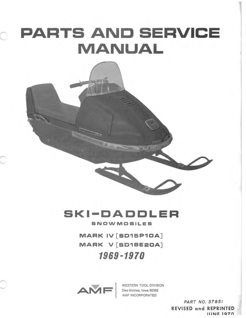
AMF 1970-1971 Series XX User manual

Parts
and Service
Manual
1970-
1971
Series XX
Part
No.
1002473
AMF WESTERN TOOL DIVISION
Parts and Service Department
Whiteford Road, York, Pennsylvania,
17402.717/848
-1177
"AMF INCORPORAT
ED


c
c
.-...
~I
CONTENTS
TABLE
Of
CONTENTS
Page
INTRODUCTION
......................................................................
..
............................................................................
PREDELIVERY
INSTRUCTION
S .......................................................................................................................... 1
Install Ski Assembly ............................................................................................................................................ 1
Ski Damper Adju
st
ment ....................................................................................................................................... 2
Install Windshield Assembly .................................................................................................................................. 2
Fuel Mixture Instructions ..................................................................................................................................... 2
Lubrication .......................................................................................................................................................... 3
SER
VICE
AND
REPAIR
.......................................................................................................................................... 3
Hood Removal
an
d Installation ............................................................................................................................ 3
Hood Assembly Repair ......................................................................................................................................... 3
Repl
ace
Lamp Assembl
ies
.................................................................................................................................... 4
Steering and Ski Assembly Alignment ................................................................................................................. 4
Steering Damper Adjus
tm
en
t ............................................................................................................................... 4
To
Remove Drive Chain ....................................................................................................................................... 4
Drive
Ch
a
in
Adjustment .......................................................................................................................................
To
Remove Varia
bl
e-Speed Drive Belt .................................................................................................................
Variable
-S
peed
Drive Belt Adjustment .................................................................................................................
To
Remove Drive Clutch .....................................................................................................................................
5
5
6
6
Drive Clutch Alignment ....................................................................................................................................... 6
To
Remove Driven Clutch .................................................................................................................................... 7
To
Remove Brake Assembly ................................................................................................................................. 7
Brake Adjustment ................................................................................................................................................. 7
To
Remove
Carburetor
....................
..
..........................................................................._.............................
..
......... 7
Carburetor Adjustments .............................................................................................._........................................ 7
To
Remove
Fu
el Pump ................................................................................................
_...
..................................... 8
To
Remove
Engine
.......
......
...
....
.
...
.........
.......
...................
..
..............................
....
...
.....
_.......
..
.............................. 9
To
Remove
Engine
...
...............
..
....
.....
....
......................
...
...........................................................
..
...
.............
....
....
9
To
Remove
Gas
Tank ..........................................................................................................................................
10
To
Remove Muffler..............................................................................................................................................
11
To
Remove Muffler..............................................................................................................................................
11
To
Remove Exhaust Megaphon
es
........................................................................................................................
11
To
Remove Sprocket
Seals
and
Bearings
..............................................................................................................
11
To
Remove Drive Sprocket Assembly .................................................................................................................
11
To
Remove Suspension
As
se
mbly .................................................................................
_.
.....................................
12
To
Remove Traction Belt ....................................................................................................................................
12
Traction Belt Adjustment ....................................................................................................................................
12
Traction Belt Alignment ...................................................................................................................................... 12
Traction Belt Tension Adjustment .......................................................................................................................
13
Suspension System Adjustment ..........................................................................................................................
13
Spark Plug Replacement ......................................................................................................................................
13
Wiring Diagrams ...................................................................................................................................................
14
Troubleshooting.
........
...
...
..
....................................................
...
...........................................................................
14
ILLUSTRATED
PARTS
LIST .........................................................................................._.....................................
19
i/ii


)

•
c
c
-
INTRODUCTION
This
manual
has
been
pr
epared
to
provide
all
authorized
AMF
Ski-Daddler
Dealers,
Distribu
tor
s
and
technicians
with
the
instructions
necessary
to
service
and
maintain
the
1970/1971 AMF High-
Perf
ormance
Series
XX
Ski-Daddler
snowmobiles
.
IMPORTANT:
The
High-Performance
Series
XX
Ski
-Daddle
r
snowmobile
is
not
covered
by
any
AMF
warranty
either
expressed,
implied
or
statutory.
The
series
classification
for
each
snowmobile
is
clearly
shown on
the
left-hand
side
of
the
console
contro
l
panel.
The
Model
Number
and
Serial
Number
are
permanently
stamped
on
the
nameplate
attached
to
the
rear
right-hand
side
of
the
main
frame
as-
sembly.
When
ordering
accessories
or
replacemen
t
parts,
always
indicate
the
correct
Model
Number
and
Serial
Number
as
shown on
the
'
nameplate.
The
following
list
identifies
the
Ski-Daddler
series
classification,
corresponding
model
numbers
and
e
ngine
designation
covered
in
this
manual.
SERIES
CLASSI
FICATION
MODEL
NUMBER ENGINE
XX-1300 SD15M28A 292
XX-1340 SD15M26A 340
XX-1400 SD15M22B 399
XX-1440 SD15M23B 439
XX-1650 SD18M29A 650
XX
-1800 SD18M30B 793
SD15M28A
111
[Manufacturer's
engine code
number
M =Manual
start
Traction
belt
width
in
inches
Ski-Daddler
This
manual
is
presented
in
two
sections.
The
first
secti
on,
Maintenanc
e,
provides
the
instructions
necessary
for
maintenance
and
service
while
the
sec
ond
section,
the
Illustrated
Parts
List
is
pro-
vided
to
facilitate
the
ordering
of
spare
and
replace-
ment
parts.
The
Parts
List
section
also
contains
a
numerical
listing
of
all
items
shown
in
the
Illustrated
Par
ts
List.
Thus,
if
the
part
number
is
known
but
not
its
applica
tio
n,
refer
to
the
numerical
list.
If
the
part
100
2
-1
73
INTRODUCTION
taSld
number
is
not known,
locate
the
item
on
the
illus-
tration
to
obtain
the
index
number
keyed
to
the
applicab
le
parts
list.
If
the
information
in
this
manual
is
not
applicable
to
all
models,
the
exceptions
will
be
noted
and
the
cor-
rec
t
infor
mat
ion
for
the
particular
model
will
be
given.
PREDELIVERY
IN
STRUCTIONS
The
1970/1971
Ski-Daddlers
are
shipped
completely
assembled
except
for
th
e
windshield
assembly
and
the
ski
assembly.
The
windshield
and
ski
assemblie
s
will
be
found
in
the
shipping
container.
Carefully
open
the
container
and
immediately
inspect
the
eqUipment
for
any
damage
or
missing
items.
The
spindle
pads
and
locknuts
will
be
found
in
the
plastic
bag.
The
bushings
and
screws
are
installed
on
the
spring
mounting
bracket
to
retain
the
ski-dam
per
during
shippi
ng.
IMPORTANT:
The
owner
must
retain
the
Ski-
Daddler
Inspection
Record,
Form
No. 4477QA.
This
form
must
be
shown
to
the
dealer
should
any
claim
arise
for
missing
or
damaged
parts.
Install
Ski
Assembly
•
Remove
the
screw
(3,
figure
1)
and
bushing
se
-
curing
the
ski-damper
to
the
spring
mounting
bracket.
Figure 1

PREDEL
I
VERY
INSTRUCTIONS
•
Place
the
spindle
pad
(1)
in
the
s
pring
mounting
bracket
with
the
thicker
section
and
the
directional
arrow
on
the
pad
pointing
forward
.
•
Secure
the
ski
assembly
to
the
lower
end
of
the
spindle
tube
assembly
by
insert
i
ng
the
s
crew
(3)
and
bushing
through
the
s
ki
damper,
spring
mo
untin
g
bracket
and
spindle
tube
as
ill
u
strated.
Apply 30
foot-pounds
torque
to
the
locknut
(2). Do not o
ver-
tighten
locknut
as
ski
assembly
should
flo
at
fr
eely
on
the
spindle.
NOTE:
Be
certain
to
install
sk
ii
s with p
iv
ot
of
ski
damper
forward
and
adju
s
ting
n
ut
to
out
s
id
e ofSki-
Daddler
as
illustrated.
•
Repeat
procedure
for
oppos
ite
s
ki
.
NOTE:
Properly
installed
skii
s should
to
e
out
0- to
1/
2-
inch
at
the
front
end
and
s
hould
be
symme
t
ric
al
a
bout
the
centerline
of
the
sled.
If
ne
c
ess
a
ry,
re
f
er
to
paragraph
Steering
and
Ski
As
s em
bl
y Al
ign
m
ent
procedures.
Ski
Damper
Adjustment
To
adjust
the
sk
i
damper
ass
em
blies,
rem
ove the
cotter
pin
(figure
1)
and
tig
ht
en
or
loo
se
n
th
e ad-
ju
s
ting
nut
as
required
to
ach
iev
e t
he
de
sire
d
tension.
Replace
cotter
pin
and
repeat
p
roc
e
du
re
on oppos
ite
ski
a
ss
embly.
Install Windshield As
sembly
•
Disco
n
nect
hood
ha
rness at the quick d
is
-
connect.
•
Remove
hood
assembly.
Re
fer
to
Hood R
em
o
val
and·
Installation
procedure.
•
Back
off
the
locknut
(figu
re
2)
and
r
em
o
ve
the
7/8
-
inch
length
screw
us
ed
to
se
c
ur
e
th
e hood
harnes
s
clip
and
the
end
of
th
e
ri
ght-h
an
d
moun
t
ing
st
rip
to
the
hood.
NO
TE: The hood h
arness
clip,
locknut
and
7/8
-
inch
le
ngth
sc
re
w (figu
re
2)
are
us
ed
on
the
15-
inch
trac
k sleds only.
•
Remove
the
remaining
s
crews
secu
ri
ng
th
e
right-
and
left-hand
mounting
s
tr
i
ps
to
th
e hood.
Remove
the
mounting
strips.
•
Remove
the
protective
pla
s
tic
cover
fr
om the
windshield.
Place
the
windshield
in
po
s
ition
on
th
e
hood
assembly.
Replace
the
mo
unting
st
r
ips
as
shown
in
figure
2.
2
MOUN
TING
ST RIP.
RH
7/8
-I
NCH
LONG
ONLY)
WIN
DSH IELD
TR
IM
M
OUNTING
STRIP
.
LH
•
TOE
OUT 0-
TO
1
/Z
-
IN
CH
MAX
I
MUM
15
-I
NCH TRACK SLED
SH
O
WN
Figure 2
•
Usin
g
th
e
original
screws,
loosely
secure
the
mo
unting
strips
and
windshield
to
the
hood
as
s
embly
st
arting
at
the
center
and
working
to
the
sides
.
Be
certain
to
position
the
7/8
-
inch
l
ength
screw
in
the
end
position
shown
in
figure
2.
•
Engage
the
en
ds of
the
mounting
strips
over
the
t
rim
st
rip
on t
he
winds
h
ield
and
then
tighten
the
screws
,
startin
g
at
the
sides
and
working
to
the
center.
Rem
o
ve
the
protective
_
~overing
from
the
mountin
g
strips.
NOTE:
Check
mounting
s
tr
ips
for
sharp
edges
or
corners
.
Use
a
fine
-
tooth
file
to
sm
ooth
any
sh
arp
edges
and
corners.
•
Attach
the
hood
harness
clip
to
the
7/8
-
inch
length
screw
and
secure
wi
th
locknut.
•
Repla
ce the hood
assembly.
Fuel Mixture
In
structions
r-
, -W- A- R-N-
IN
-G-"I
Never
fill
the gaSOline
tank
while
the
engine
is hot. Wipe off
any
spilled
gasoline
b
ef
o
re
attempting
to
start
engine.
1002473
"

c
--
The
correct
oil-to-ga
soline
ra
ti
o
is
20: 1 (20
parts
re
gular
gasoline
to
1 p
art
oil). Too
much
oil
will
ca
us
e
carbon
deposits.
Too
lit
tle
oil
or
a
poor
mix
will
cause
insufficient
l
ubri
ca
tion
an
d
possible
engi
ne
damage.
IM
PO
RT
ANT:
Gasolin
e and o
il
should
be
mixed
at
temp
er
ature
s above
ze
ro. At
temperatures
below
ze
ro
gas
and
oil
mix
with
di
ffi
cult
y.
Fuels
containing
additiv
es
are
not
rec
ommended
for
use
in
Ski-Daddler
engines.
For
mixi
ng
wit
h
gaso-
lin
e,
use
Citgo,
Rislon
e
or
Kendall o
il
prepa
r
ed
excl
u
sively
for
use
in
a
ir-cooled,
2-c
y
cle
engines
.
IMPORTANT: Some
outboard
motor
o
il
s
contain
an
addit
i
ve
that
works
we
ll
in
outboa
rd
motors
tha
t
ope
rate
at
much
lower
temp
e
ratur
es
because
they
ar
e
water
cooled.
However,
th
e addi
ti
ves
may
cause
spark
plug
fouling
in
the
air-cool
ed engi
nes
u
sed
on
Ski-
Daddler
snowmobil
e
s.
U
se
a
mixture
of
gasolin
e
and
o
il
as
shown
in
the
Fuel
Mixture
Chart.
Neve
r u
se
g
asoline
left
over
fr
om
the
summer
or
previous
win
ter.
FUEL
MIXTURE
CHA
RT
OIL
(Ounces
)
o 4 8
12
16
20 24
28
32
36
40
5
4
3
2
/
o
GA
S
OLINE
(Gallons)
v
/"
/
./
-"
/ V
./
/"
V
./
/ V
./
~
"
./
/
.,
~
u.
s.
Ga
ll
on,
I
m
pe
,;~
1
Ga
l
ion,
T-
GASOLINE/OIL
RATlO-
20
to 1
Mix
the
gasoline
and
oil
thoroughly
in a
clean
con-
tain
er
kept
for
this
purpos
e only. The
best
way
to
ens
ure
a good
mix
is
to
pou
r
th
e
oil
into
a
container
with
about
one
gallon
of
ga
s
oline
and
mix
thoroughly.
Then
add
additional
amounts
of
ga
s
olin
e as shown on
the
Fuel
Mixture
Chart.
Fill
Ski-D
addl
er
gas
t
ank
from
this
separate
container
of
mix
ed fue
l.
Use
a
funnel with a
fine-screen
s
train
er when
filling
th
e
tank.
1002473
3
PREDELIVERY
INSTRUCTIONS
USia
Lubrication
A
low-temperature
grease
must
be
applied
to
the
zerk
fittings
located
on
the
steering
spindle
tube
s;
after
apprOximately
each
20
hours
of
use.
The
chain
case
housing
must
be
checked
after
each
10
hours
of
use
and
No. 2
lithium
bearing
grease
added
as
required.
The
bearing
cup
retainers
that
hold
the
drive
and
idler
sprocket
seal
bearings
should
be
repacked
with
No. 2
lithium
bearing
grease
whenever
the
bearings
are
removed
during
normal
maintenance.
No.2
li
thium
b
ea
ri
ng gr
ease
ma
y
als
o be
applie
d to
the
i
nside
of
the
d
rive
and
idler
sprocket
bearing
re-
ta
in
ers
du
ring nor
mal
main
ten
ance
.
Grease
may
also
be
applied
as
required
to
the
wear-
plates
and
U-strap
securing
the
steering
column
to
the
roll
bar.
SERVICE
AND
REPAIR
Hood Removal
and
Installation
• To
remove
the
hood and
headlight
assembly,
disconnect
the
hood
and
the
sled
wiring
harness
at
the
quick-disconnect
below
the
console
on
the
right
-
hand
side
of
the
sled.
Release
the
hood
latch
assemblies
and
then
remove
the
hood and
headlight
assembly
by
lifting
back
section
first.
•
To
install
the
hood and
headlight
assembly,
place
the
hood
in
position
on
the
sled
so
that
the
forward
hood
clip
and
the
bottom
edge of
the
hood
engages
the
clips
along
the
inside
edge
of
the
bumper.
•
Engage
the
left-
and
right-hand
latch
assem
-
blies
and
insert
safety
pins
to
secure
the
hood·
to
the
main
frame
.
•
Connect
the
wiring
harness
using
the
connector
plug
located
below
the
console
on
the
right-hand
side
of
the
sled.
Hood
Assembly
Repair
AMF
Fiberglass
Repair
Kits
are
available
through
your
authorized
AMF
Distributor.
For
large
re
p
airs,
order
AMF
Fiberglass
Repair
Kit
No.
1510693.
Smaller
repairs
can
be
made
with
Repair
Kit No. 1510765.
Paint
all
repaired
areas
on
the
hood
using
AMF
-Orange
color
paint
available
in
easy-to-use
spray
container,
AMF
Part
No.
1510828.
Follow
the
instructions
in
the
kit
when
m
aki
ng
repa
i
rs.

SERVICE
AND
REPAIR
Replace Lamp Assemblies (15
-Inch
Sleds
Only)
Headlight.
Tb
replace
the
headlight
bulb,
raise
the
headlight
assembly;
remove
the
screws
securing
the
cover
assembly
and
remove
the
cover
assembly.
Remove
the
defecti
ve
bulb
and
replace
with
newbulb.
See
illustrated
parts
list
for
correct
replacement
part
numbers.
Taillight.
Remove
taillight
l
ens
to
expose
the
tail-
light
bulb.
Remove
the
defective
bulb
and
replace
with
a
new
bulb.
See
illustrated
parts
list
for
cor-
rect
replacement
part
numbers.
Steering
and
Ski Assembly
Alignment
Good
steering
ability
requires
that
the
skis
be
properly
set
and
aligned
with
the
sled
body when
th
e
steering
handle
is
placed
in
the
straight-ahead
position.
Remove
any
play
in
the
skis
by
pulling
the
skis
toward
the
center
of
sled
before
taking
measurements.
To
determine
that
the
skis
are
properly
aligned,
measure
the
distance
between
the
inside
edges
of
the
skis
at
the
front
end
and
at
the
rear.
Properly
aligned
skis
should
toe
out
0-
to
1/2-inch
maximum
at
the
front.
Therefore,
the
overall
measurement
at
the
front
end of
the
skis
should
be
no
more
than
1/2-inch
greater
than
at
the
rear.
If
the
skis
or
steering
mechanism
are
not
properly
set,
adjust
as
follows:
•
Place
steering
handle
in
a
straight-ahead
position.
•
Remove
the
hood
assembly.
Refer
to
Hood
Removal
and
Installation.
•
Remove
the
bolt
(1,
figure
3), two
spacers
(2),
bottom
spacer
and
locknut
securing
the
rod
end
bearing
(3)
to
the
spindle
arm
(6).
•
Loosen
the
jam
nuts
(4)
securing
both
rod
end
bearings
(3)
to
the
tie
rod
(5).
NOTE:
If
both
skis
need
adjustment,
repeat
pro-
cedure
for
the
opposite
ski.
• Move
the
affected
ski
into
proper
alignment
and
recheck
measuring
points
to
insure
that
the
skis
toe
out
0-
to
1/2
-inch
maximum
at
the
front
end
and
are
in
the
same
orientation
with
the
sled
body
as
shown
in
figure
2.
• With
skis
properly
set
and
steering
handle
in
the
straight-ahead
position,
rotate
tie
rod
(5,
figure
3)
as
required
to
bring
rod
end
bearing
(3)
in
line
with
the
spindle
arm
(6).
4
Figure 3
•
Secure
rod
end
bearing
(3)
to
spindle
arm
(6)
as
illustrated.
Check
for
proper
alignment
and
then
tighten
jam
nuts
(4)
to
secure
both
rod
end
bearings.
NOTE:
If
a
greater
adjustment
is
required
than
that
permitted
by
the
steering
linkage
assembly,
it
will
be
necessary
to
align
the
ski
by
making
the
adjust-
ment
at
the
spindle
tube
assembly
as
follows:
•
Remove
screw
(5,
figure
4)
and
locknut
(6)
se-
curing
spindle
tube
assembly
(7)
to
spindle
arm
(8).
•
Remove
spindle
arm
(8)
and
rotate
ski
and
spindle
tube
one
notch
in
the
required
direction;
replace
and
secure
spindle
arm
to
the
spindle
tube.
Apply 20
foot-pounds
torque
to
the
locknut
(6).
•
Recheck
the
skis
for
proper
toe
out
and
align-
ment
as
previously
described.
NOTE:
Ski-damper
adjustment
is
not
normally
re-
quired
during
Ski-alignment
procedures.
However,
if
adjustment
is
desired,
tighten
or
loosen
th
e
ad-
justing
nut
shown
in
figure
1
as
required
to
obtain
the
desired
tension.
Steering
Damper
Adjustment
The
steering
damper
assembly
(figure
3)
is
set
at
the
factory
and
should
require
no
further
adjust-
ments.
To
Remove Drive
Chain
•
Remove
the
hood
assembly.
Refer
to
Hood
Removal
and
Installation.
1002473
...

c
c
-
!
CAUTION
l
Always
disconnect
spark
plug
wires
before
working
on
the
engine
or
drive
elements.
•
Remove
the
locknut
securing
the
chain
cover
top
and
remove
chain
cover
top
and
spacer
sleeve.
•
Loosen
the
bolts
(1,
figure
4)
on
both
cam
up-
rights
(2)
and
rotate
the
cam
and
shaft
(3)
as
re-
quired
to
loosen
the
chain
tension.
During
reassem-
bly,
apply
30
foot-pounds
torque
to
the
bolt
(1).
•
Remove
the
cotter
pin,
slotted
nut
and
washer
securing
the
top
sprocket
to
the
driven
clutch
shaft.
Remove
the
top
sprocket
and
chain
together.
•
Reassembly
is
th
e
reverse
of
removal.
Per
-
form
drive
chain
adjustment
procedures
and
add
No. 2
lithium
bearing
grease
as
required
to
the
chain
case.
Drive Chain Adjustment
A
properly
adjusted
drive
chain
(figure
4)
should
have
a
1/8
-
to
1/4-inch
slack.
Check
and
adjust
chain
as
follows:
•
Remove
the
locknut
securing
the
chain
cover
top
and
remove
chain
cover
top
and
spacer
sleeve.
•
Rotate
the
upper
sprocket
to
tension
one
side
of
the
chain
and
then
check
the
opposite
side
for
proper
slack.
If
adjustment
is
required,
loosen
the
bolts
(1)
securing
the
cam
uprights
(2)
on
each
side.
During
reassembly,
apply
30
foot
-
pounds
torque
to
the
bolts
(1).
•
Rotate
the
cam
(3)
counterclockwise
to
tighten
or
until
the
chain
is
properly
tensioned.
Hold
the
cam
in
this
position
while
tight
ening
the
cam
upright
bolts
(1)
on
each
si
de.
Be
certain
the
lateral
align
-
ment
between
the
drive
clutch
and
the
driven
clutch
(4)
is
maintained
while
the
cam
upright
bolts
are
tightened.
•
Recheck
chain
tension
before
replacing
the
chain
cover,
top
and
spacer
sleeve.
To
Remove Variable
-Speed_
Drive Belt
•
Remove
the
drive
chain.
Refer
to
paragraph
To
Remove
Drive
Chain.
•
Remove
the
clutch
guard
assembly.
I002·17l
5
~I
SERVICE
AND
REPAIR
leSla~
•
Loose
n
the
locknut
(8,
figure
3)
and
serrated
washer
(7).
During
reassembly,
apply
10
foot-
pounds
torque
to
the
locknut
(8).
•
Push
the
driven
clutch
toward
the
drive
clutch
to
permit
removal
of
the
variable-speed
drive
belt
from
the
drive
clutch.
If
necessary
the
drive
belt
can
be
removed
from
the
drive
clutch
after
the
driven
clutch
is
removed
from
the
bearing
clamps
.
•
Remove
the
locknuts
(7,
figure
6)
securing
the
bearing
clamps
(8)
and
remove
the
bearing
clamps.
During
reassembly,
apply
5
foot-pounds
torque
to
the
locknuts
(7).
•
Lift
the
driven
clutch
and
drive
belt
clear
of
the
brake
assembly
and
remove
the
variable-speed
drive
belt.
•
Install
replacement
drive
belt.
Use
AMF
Part
No. 37880 on
Models
SD15M26A
and
SD15M28A-
AMF
Part
No. 37492
on
Models
SD15M22B
and
SDI5M23B;
AMF
Part
No. 34635 on
Models
SDI8M-
29A
and
SD18M30B.
NOTE:
Variable-speed
drive
belt
installation
pro-
cedures
are
the
reverse
of
removal
except
that
the
belt
must
first
be
placed
around
the
driven
clutch
and
then
around
the
drive
clutch.
Afterin
s
tallation,
perform
the
drive
chain
adjustment,
variable-speed
belt
adjustment
and
the
drive
clutch
alignment
procedures.
Figure 4

SERVICE
AND
REPAIR
Variable-Speed Drive
Belt
Adiustm~nt
Proper
tension
for
a new
drive
belt
should
be
ob-
tained
when
the
clutch
centers
are
set
to
the
B
dimension
shown
in
figure
5
for
the
applicable
model
snowmobile.
IMPORTANT: Do
not
use
antislip
belt
dressing.
Belt
slippage
is
a
safety
feature
which
prevents
overstressing
drive-system
components
.
•
To
adjust
drive
belt
tension,
loosen
the
locknut
(8,
figure
3)
securing
the
clutch
rod
tensioner
to
the
main
frame
assembly.
NOTE:
If
the
drive
belt
is
wearing
unevenly,
check
alignment
as
described
in
Drive
Clutch
Alignment
procedures.
•
Move
the
driven
clutch
(9)
in
the
direction
re-
quired
to
obtain
proper
belt
tension.
Hold
this
posi-
tion
while
tightening
the
locknut
to
secure
the
clutch
rod
tensioner.
Be
certain
the
washer
(7)
and
bar
serrations
are
properly
engaged.
Apply 10
foot-
pounds
torque
to
the
locknut
(8).
To
Remove
Drive Clutch
•
Remove
the
hood
assembly.
Refer
to
Hood
Removal
and
Installation.
!
CAUTION
!
Always
disconnect
spark
plug
wires
before
working
on
the
engine
or
drive
elements.
•
Remove
the
clutch
guard
assembly.
•
Loosen
the
locknut
(8,
figure
3)
and
serrated
washer
(7)
securing
the
clutch
rod
tensioner
to
the
main
frame.
During
reassembly,
apply 10
foot-
pounds
torque
to
the
locknut
(8).
•
Push
the
driven
clutch
toward
the
drive
clutch
to
permit
removal
of
the
variable-speed
drive
belt
from
the
drive
clutch.
If
necessary
remove
belt
after
drive
clutch
is
removed
from
engine.
• To
remove
the
drive
clutch,
remove
the
clutch
adapter
bolt
and
washer.
If
necessary,
use
a
clutch
puller
and
remove
the
drive
clutch.
NOTE:
During
reassembly
on
Models
SD15M28A and SD15M26A
only,
apply
50
to
60
foot-pounds
torque
to
the
clutch
bolt.
All
other
models
require
70 ± 5
foot-pound
s
torque.
6
•
Reassembly
is
the
reverse
of
removal.
Per-
form
variable-speed
dri
ve
belt
adjustment
and
drive
clutch
alignment
procedure
s.
Drive
Clutch
Alignment
•
Remove
the
hood
assembly.
Refer
to
Hood
RemOVal
and
Installation.
Always
disconnect
spark
plug
wir
es
before
working
on
the
engine
or
driv
e
elements.
•
Remove
the
clutch
guard.
•
Loosen
the
engine holddown
nuts
(figur
e
5)
se-
curing
the
engine
supports
to
engine mount
straps
.
•
Place
a
straightedge
on
the
fixed
face
of
th
e
drive
clutch
and move
th
e engine
until
th
e
offset
between
the
straightedge
and
the
front
and
rear
edges
of
the
driven
clutch
is
set
to
the
A
dimension
as
shown
in
figure
5.
Rotate
driv
en
clutch
90-
degrees
and
repeat
proc
e
dure.
•
Tighten
engine holddown
nuts
and
recheck
alignment.
Apply
25
foot-pounds
torque
when
tightening
the
engine holddown
nuts.
A
0.
24
0.24
0.26
0.26
0.26
0.26
B
12·1/2
12-1/2
12·1/2
12·1/2
12·1/2
12·1/2
c
(TORQUE)
FT
-
LB
MODEL
NO.
55
±.5
S
D15M28A
55.±
5 S
D15M26A
70
.±
5
SD15M22B
70
.±
5
SD15M23B
70
.±
5
SD18M29A
70
.±
5
SD18M30B
Figure 5
ENGINE
CLUTCH
292
780M
340
780M
399
9·R
439
9·R
650
11·R
793
11·R
HOLDDOWN
NUTS
VIEW
0
1002473
)
)

•
c
To
Remove Driven Clutch
NOTE:
The
procedures
required
to
remove
the
driven
clutch
are
the
same
as
those
desc
ri
bed
in
paragraph
To
Remove
Variable
-S
peed
Drive
Belt.
To
Remove Brake
Assembly
•
Remove
hood
assembly
.
Refer
to Hood
Removal
and
Installation.
! CAUTION l
Always
disconnect
the
sparkplugwires
before
working
on
the
engine
or
drive
elements.
•
Disconnect
brake
cable
and
housing
(3,
figure
6)
at
brake
mounting
bracket
and
at
brake
actuating
lever.
•
Remove
the
bolts
and
lockwashers
securing
the
mounting
bracket
to
the
driven
clutch
mo
untin
g.
•
Remove
the
brake
assembly.
•
Installation
procedures
are
the
reverse
of
re-
moval.
Refer
to
Brake
Adjustm
ent
proc
edures.
Brake
Adjustment
•
To
adjust
the
brake
pad
s (5,
figure
6)
to
the
disk
(1),
remove
the
cotter
pin
(2)
and
tighten
or
lo
o
sen
Figure 6
I 'If).!
17
i 7
~I
SERVICE
AND
REPAIR
If4
Si
aij
the
castle
nut
(4)
as
required
to
permit
the
brake
pads
(5)
to
just
clear
the
brake
disk.
Reinstall
the
cotter
pin.
To
adjust
for
excessive
play
in
brake
cable
or
lever
position,
loosen
jam
nuts
(6)
and
move
brake
housing
(3)
as
required.
Tighten
jam
nuts.
To
Remove
Carburetor
•
Remove
the
locknut
securing
the
throttle
rod
screw
to
the
carburetor
linkage.
Remove
th
e
throttle
rod
screw
and
jam
nuts.
•
Remove
the
screws
securing
the
ram
tube
to
the
carburetor
and
remove
the
ram
tube.
•
Disconnect
the
fuel
lines
at
the
carburetor.
Wipe up
any
spilled
gasoline
immediately.
Be
cer
-
tain
to
note
the
position
of
the
gas
line
and
impulse
lines
to
insure
proper
reassembly.
•
Remove
the
jam
nuts
and
lockwashers
securing
the
carburetor
to
the
intake
manifold
and
remove
the
carburetor.
•
Remove
the
gasket.
Do
not
damage
the
gasket
if
required
for
reassembly.
NOTE:
Replacement
carburetors
are
supplied
with
a new
gasket.
•
Installation
is
the
reverse
of
removal.
Adjust
the
carburetor
as
described
in
the
Carburetor
Adjustment
procedures.
Carburetor
Adjustments
The
carburetors
used
on
Models
SD15M22B
and
SD15M23B
are
float
type
carburetors
that
utilize
external
pumps.
The
high-
and
low
-
speed
adjust-
ment
screws
for
these
carburetors
are
located
on
top
of
the
carburetor
and
are
easily
identified
by
the
letters
HI
and
LO.
The
adjustment
screws
for
all
other
type
carburetors
are
located
on
the
sides
as
shown
in
figure
7.
When
adjusting
the
carburetor,
best
results
will
be
obtained
if
the
adjustments
are
made
on a
warm
engine.
During
carburetor
adjustments,
DO
NOT
FORCE
ADJUSTMENT SCREWS INTO SEATS.
• TO ADJUST CARBURETOR -
Close
the
high-
speed
jet
(DO
NOT
FORCE).
Then
open
the
high-
speed
jet
(figure
7)
to
the
settings
shown
on
the
carburetor
settings
chart
for
the
particular
engine
(see
figure
8).

~t&:4Mlal
SERVICE
AND
REPAIR
I~
!~~CAUTION
The
engine
can
be
seriously
damaged
if
operated
with a
lean
gas
mixture
(high-
speed
jet
turned
in
too
far)
.
•
Turn
the
low
speed
jet
(idle-mixture
screw)
shown
in
figure
7
all
the
way
in
(DO
NOT FORCE),
then
open
as
shown
in
figure
8
for
the
particular
engine.
This
adjustment
controls
the
mixture
at
idling
speeds.
A
lean
idle
mixture
will
result
in
poor
acceleration.
Figure 7
Keep
the
idle
speed
slower
than
the
clutch
engaging
speed
by
adjusting
the
idle-speed
screw.
NOTE: Do
not
use
the
low-speed
jet
to
adjust
for
idle
speed.
To
Remove
Fuel
Pump-
NOTE:
Figure
7
shows
a
throttle-wire.
If
the
throttle
plate
fails
to
open
completely
when
the
throttle
control
lever
is
depressed,
loosen
th
e
throttle-wire
adjustment
screw
and
readjust
the
wire
as
required
to
open
the
throttle.
Models SD1SM22a and SD1SM23B only
!~
~~~TION
!
Always
disconnect
the
sparkplugwires
before
working
on
the
engine
or
drive
elements.
CARBURETOR SETTINGS CHART
SERIES
MODEL NO. CLASSIFICATION ENGINE HIGH-
SPEED
JET LOW-SPEED JET
+
1/8
0 +
1/8
SD15M28A XX-1300 292 1 _ 0
pen
1-
1/8
_ 0 Open
SD15M26A
XX
-1340 340 1 +
1/8
_ 0 Open +
1/8
1-1/8 _ 0 Open
SD15M22B XX-1400 399 1 + 1/8 0
_ 0
pen
1-1/2 +
1/8
Open
- 0
SD15M23B +
1/8
0 +
1/8
XX
-1440 439 1 _ 0
pen
1-1/2 _ 0 Open
SD18M29A XX-1650 650 +
1/8
7/8
_ 0 Open +
1/8
1-1/8 _ 0 Open
SD18M30B XX-1800 793 7
/8
~
~/8
Open +
1/8
1-1/8 _ 0 Open
-
The
above
carburetor
settings
are
for
factory
stock
engines.
Modified
engines,
exhaust
systems,
carburetion
and
various
altitudes
may
require
different
settings
for
satisfactory
operation.
Figure 8
8 1002473
•

D
c
-
•
Disconnect
the
gasoline
lines
at
the
fuel pump.
Note
the
pOSition of
the
lines
to
insure
proper
re-
assembly.
Disconnect
the
impulse
line.
Wipe up any
spilled
gasoline
immediately.
•
Remove
the
locknut
and
washer
securing
the
fuel
pump
to
the
mainframe.
Remove
the fuel
pump
and
mounting
bracket
as
a
unit.
•
Reassembly
is
the
reverse
of
removal.
To
Remove Engine -Models SD15M28A,
SD15M26A, SD15M22B and SD15M23B only
•
Remove
the
hood
assembly.
Refer
to
Rood
Removal
and
Installation.
!~~CAUTIO~
Always
disconnect
the
sparkplugwires
before
working
on
the
engine
or
drive
elements.
•
Remove
the
drive
clutch.
Refer
to
paragraph
To
Remove
Drive
Clutch.
NOTE:
The
Illustrated
Parts
List
section
of
this
manual
contains
detailed
exploded
views
of
the
engine and
support
assemblies
whichwill
be
helpful
if
referred
to
during
engine
removal
procedures.
For
engine
maintenance
instruction,
refer
to
the
engine
manual
supplied
with
each
sled.
•
Remove
the
caps
crews
and
washers
securing
the
carburetor
heat
shield
to
the
intake
manifold
and
remove
the
heat
shield.
•
Disconnect
the
gas
lines
at
the
carburetors.
Disconnect
impulse
lines
at
the
engine. Wipe up
any
spilled
gasoline
immediately.
Note
the
position
of
all
lines
to
insure
proper
reassembly.
•
Remove
the
capscrews
and
spring
lockwashers
securing
the
left-
and
right-hand
intake
manifold
to
the
engine.
Remove
the
intake
manifolds,
carbure-
tors
and
ram
tubes
as
a
unit.
•
Remove
the
engine-to-manifold
gasket
if
re-
quired
for
reassembly.
NOTE: New,
replacement
engines
are
supplied
with
new
engine-to-manifold
gaskets.
•
Remove
the
exhaust
system
on Models
SDI5M-
22B
and
SD15M23B only.
Refer
to
paragraph
To
Remove
Muffler.
1
00
2473
9
ERVICE
AND
REPAIR
USia
•
Remove
the
heat
shield
attach
ed to
the
roll
bar
and
main
frame
between
the
engine and
the
muffler.
•
Disconnect
the
engine
wiring
harne
ss
and
loosen
or
remove
all
wiring
holddown
clips.
Dis-
connect
the
ground
lead.
•
Remove
the
locknuts,
washers,
rubber
spacers
and
bushings
securing
the
engine and
engine
mounting
straps
to
the
main
fram
e. NOTE: The
carriage
bolts
are
held
in
position
with
Tinnerman
nuts
and
need
not
be
removed.
Do
not
remove
the
shockmounts
unless
it
is
necessary
to
replace
them.
During
reassembly,
tighten
the
locknuts
sufficiently
to
allow
a 5
/16
-inch
clearance
between
bottom
of
the
shock
mount and top
surface
of
the
main
frame.
IMPORTANT: Be
certain
all
wiring
and
gasoline
lines
are
clear
before
attempting
to
remove
the
engine.
•
Lift
the
engine and engine mounting
straps
until
the
straps
are
clear
of
the
carriage
bolts
and
re
-
move
the
engine and
straps
as
a unit.
•
Release
the
exhaust
manifold
at
the
engine on
Models SD15M28A and SD15M26A only.
Refer
to
paragraph
To
Remove
Muffler.
•
Remove
the
bolt
and
washers
securing
the
engine
to
the
engine mounting
plate
and
remove
the
engine.
During
reassembly,
apply
loc
-
tite
to
the
bolt
threads
and
tighten
bolts
to
18
foot-pounds
torque.
•
Installation
is
the
reverse
of
removal.
To
Remove Engine -
Models SD18M29A and SD18M30B only
•
Remove
the
hood
assembly.
Refer
to Hood
Removal
and
Installation.
I
CA~TION
Always
disconnect
the
sparkplugwires
before
working
on
the
engine
or
drive
elements.
•
Remove
the
drive
clutch.
Refer
to
paragraph
To
Remove
Drive
Clutch.
NOTE:
The
Illustrated
Parts
List
section
of
this
manual
contains
detailed
exploded
views
of
the
engine and
support
assemblies
which
will
be
helpful
if
referred
to
during
engine
removal
procedures.

~t.!2131
SERVICE
AND
REPAIR
I~
For
engine
maintenance
instructions,
refer
to
the
engine
manual
supplied
with
each
sled.
•
Disconnect
the
gas
lines
at
the
carburetors.
Disconnect
impulse
lines
at
the
engine. Wipe up
any
spilled
gasoline
immediately.
Note
the
position
of
all
lines
to
insure
proper
reassembly.
•
Disconnect
the
throttle
cable
at
the
carburetor
linkage
and
remove
the
metric
nuts
and
lockwashers
securing
the
carburetors
and
carburetor
linkage
to
the
engine.
Remove
the
carburetors
and
linkage
as
a
unit.
On Model SD18M29A,
remove
the
carburetor,
linkage
and
intake
manifold
as
a
unit.
•
Remove
the
carburetor
heat
shield.
•
Remove
the
engine-to-manifold
gasket
if
re-
quired
for
reassembly.
NOTE: New,
replacement
engines
are
supplied
with new
engine-to-manifold
gaskets
for
Model SD18M29A. On Model SD18M30A,
new
gaskets
are
supplied
with
the
carburetors
only.
•
Disconnect
the
engine
wiring
harness
and
loosen
or
remove
all
wiring
holddown
clips.
Dis-
connect
the
ground
lead.
•
Remove
the
clamps
securing
the
exhaust
mega-
phones
to
the
megaphone
support
weldment.
Release
the
extension
springs
at
the
engine
and
remove
the
megaphones.
Note
the
position
of
the
clamps
to
insure
proper
reassembly.
•
Remove
the
bolts
and
washers
securing
the
engine
mounting
straps
to
the
main
frame
and
shock
mounts.
Remove
the
engine
and
mounting
straps
clear
of
the
sled.
During
reassembly,
do
not
tighten
the
engine
mount
bolts
until
after
completing
clutch
alignment.
After
clutch
alignment,
tighten
engine
mount
bolts
to
9
foot-pounds
torque.
NOTE:
If
more
clearance
is
desired,
remove
the
seat
assembly.
The
locknuts
and
washers
securing
the
seat
to
the
main
frame
are
accessible
through
the
seat
tote
pouch.
•
Remove
the
bolts
and
washers
securing
the
engine
mount
frame
to
the
engine.
Remove
the
engine.
During
reassembly,
apply
loc-tite
to
the
bolt
threads.
•
Installation
is
the
reverse
of
removal.
To
Remove
Gas
Tank
•
Remove
the
hood
assembly.
Refer
to
Hood
Removal
and
Installation.
10
1
CAUTION
!
Always
disconnect
spark
plug
wir
es
before
working
on
the
engine
or
drive
elements.
•
Check
gas
cap
and
indicator
assembly
to
be
certain
tank
is
empty,
or
nearly
empty.
•
Remove
the
gas
cap
and
indicator
assembly
(1,
figure
9).
•
Remove
the
bolts
(3)
and
washers
securing
the
gas
spill
chute
(2)
to
the
main
frame
and
remove
the
gas
spill
chute.
•
Disconnect
the
tank
-
to-carbure
tor
gas
lines
(6)
at
the
gas
tankoutletfitting
(5). Wipe up
any
spilled
gasoline
immediately.
•
Remove
the
gas
tank
(4) by
carefully
sliding
the
tank
up and away
from
main
frame.
IMPORTANT:
Do
not
damage
the
gas
tank
outlet
(5)
when
removing
the
tank.
Do
not
attempt
to
make
any
repairs
to
the
gas
tank
,
Use
extreme
care
when
removing
the
gas
tank.
Do
not
remove
tank
near
flame
or
open
fire.
•
Gas
tank
installation
procedures
are
the
re-
verse
of
removal.
NOTE:
If
the
original
tank
is
not
to
be
installed,
it
will
be
necessary
to
remove
the
gas
tank
outlet
(5)
and
the
attached
gas
line
filter;
also
the
pressure
relief
valve
(8).
These
items
are
to
be
i
nstalled
on
the
replacement
tank.
Figure 9
1002473
)
)

e
c
c
--
To
Remove
Muffler-
Models SD15M28A
and
SD15M26A only
•
Remove
the
hood
assembly
.
Refer
to
Hood
Removal
and
Installation.
Always
disconnect
the
sparkplugwires
before
working
on
the
engine
or
drive
elements.
•
Loosen
the
clamp
securing
the
muffler
to
the
dual-exhaust
manifold.
•
Loosen
the
bolt
and
nut
securing
the
muffler
to
the
mounting
band
assembly.
Remove
the
muffler.
•
Installation
procedures
are
the
reverse
of
removal.
To
Remove Muffl
er-
Models SD15M22B
and
SD15M23B only
•
Remove
the
hood
assembly.
Refer
to
Hood
Removal
and
Installation.
!
CAUTI~~
Always
disconnect
the
sparkplugwires
before
working
on
the
engine
or
drive
elements.
•
Remove
the
screws,
washers
and
locknuts
se-
curing
the
muffler
band
asse-mblies
to
the
muffler
bracket
and
to
the
heat
shield.
•
Remove
the
screws,
washers
and
locknuts
se-
curing
the
hea
t
shield
to
heat
shield
support
attached
to
the
roll
bar.
Remove
the
heat
shield.
•
Remove
the
retaining
rings
securing
the
muf-
fler
weldment
to
the
exhaust
manifolds.
•
Remove
the
muffler
weldments.
Note
the
posi-
tion
of both
mufflers
to
insure
proper
reassembly.
•
Remove
the
muffler
band
assembly
from
each
muffler.
•
Installation
procedures
are
the
reverse
of
removal.
1002473
11
SERVICE
AND
REPAIR
To
Remove Exhaust
Megaphones
-
Models SD18M29A
and
SD18M30B only
NOTE: Model SD18M30B
has
a
three
megaphone
system
whereas
Model SD18M29A
utilizes
a two
megaphone
system.
•
Remove
th
e hood
assembly.
Refer
to
Hood
Removal
and
Installation.
I
~~UTIO~:]
Always
disconnect
th
e
sparkplugwires
before
working
on
the
engine
or
drive
elements.
•
Remove
the
clamps
securing
the
megaphones
to
the
megaphone
support
weldment.
Note
the
position
of
each
clamp
to
insure
proper
reassembly.
•
Release
the
extension
springs
securing
the
megaphones
to
the
engine
exhaust
manifold
and
re-
move
the
megaphones.
•
Installation
procedures
are
the
reverse
of
removal.
To
Remove Sprocket Seals
and
Bearings
•
Sprocket
seals
andb
earings
are
located
on
each
end of
the
drive
sprocket
assembly
drive
shaft.
To
replace
the
seals
or
bearings
it
will
be
necessary
to
remove
the
drive
sprocket
assembly
as
described
in
the
follOwing
paragraph.
To
Remove Drive Sprocket Assembly
•
Remove
the
hood
assembly
and
set
the
machine
on
its
right-hand
side.
f
C~UTION
Always
disconnect
spark
plug
wires
before
working
on
the
engine
or
drive
elements.
•
Remove
the
suspension
assembly.
Refer
to
paragraph
To
Remove
Suspension
Assembly.
•
Remove
the
lower
sprocket
from
the
drive
sprocket
shaft
and
remove
the
sprocket
and
chain
as
described
in
paragraph
To
Remove
Drive
Chain.

SERVICE
AND
REPAIR
•
Using
a
screw
driver,
carefully
pry
the
oil
seals
(figur
e 10) away
from
the
bearings
at
each
end of
the
drive
shaft.
•
Remove
the
carriage
bolts
and
nuts
securing
the
bearing
retainers
to
each
side
of
the
main
frame.
Remove
the
retainers.
During
reassembly
apply No.
2
lithium
bearing
grease
to
the
bearing
retainers.
• Move
the
drive
shaft
and
sprocket
assembly
toward
the
chain
side
until
the
opposite
end of
the
shaft
clears
the
other
side.
Remove
the
drive
sprocket
assembly.
NOTE: With
the
removal
ofthe
drive
sprocket
assembly,
the
traction
belt
will
also
be
free
for
removal.
•
To
replace
the
sprockets,
remove
the
ball
bearing,
oil
seal,
collar
and
idler
wheel.
Remove
the
screws
and
nuts
securing
the
support
plate
and
sprocket
to
the
drive
shaft
and
sprocket
plate
assembly.
Remove
the
sprocket.
•
Reassembly
is
the
reverse
of
removal
.
During
reassembly
follow
instructions
outlined
in
the
para-
graphs
Traction
Belt
Tension
Adjustment,
Traction
Belt
Alignment
and
Drive
Chain
Adjustment.
Figure 10
To
Remove
Suspension
Assembly
•
Remove
the
hood
assembly
and
set
the
machine
on
its
right-hand
side.
\:
CAUTION
Always
disconnect
spark
plug
wires
before
working
on
the
engine
or
drive
elements.
12
•
Remove
the
screws
(figure
11)
andlockwashers
securing
the
back
end of
the
suspension
assembly
to
main
frame.
•
Pivot
the
suspension
assembly
and
traction
belt
about
the
front
axle
to
approximately
90
degrees.
•
Remove
screws
and
lockwashers
securing
the
suspension
assembly
to
the
front
end of
the
main
frame
and
remove
the
suspension
assembly.
•
Installation
is
the
revese
of
removal.
During
reassembly,
follow
the
instructions
outlined
in
paragraphs
Traction
Belt
Tension
Adjustment,
Traction
Belt
Alignment and
Suspension
System
Adjustment.
To
Remove Traction Belt
To
remove
or
replace
the
traction
belt
itis
neces-
sary
to
first
remove
the
suspension
assembly
and
then
the
drive
sprocket
assembly.
Refer
to
the
applicable
paragraphs
for
removal
procedures.
IMPORTANT: When
installing
the
traction
belt,
follow
the
instructions
outlined
in
paragraphs
trac-
tion
Belt
Tension
Adjustment,
Traction
Belt
Align-
ment
and
also
recheck
Suspension
System
Adjust
-
ment.
Traction Belt Adjus
tment
IMPORTANT: The
traction
belt
must
be
checked
regularly
for
proper
alignment
and
tension.
When
necessary
to
adjust
the
belt,
first
perform
the
trac-
tion
belt
alignment
and
then
complete
the
traction
tension
adjustment.
Traction Belt
Alignment
•
Set
the
snowmobile
on a
level
surface
and
raise
the
back
end.
• Stand to the
rear
of
sled
and
visually
check
the
space
between
the
slide
rail
and
the
edges
of
the
track.
NOTE: On a
properly
aligned
track
this
space
shoul
d
be
the
same.
Start
the
engine and
again
visually
check
to
be
certain
the
track
remains
centered
while
the
track
is
running.
•
If
the
track
is
not
centered,
stop
the
engine
and
on
that
side
where
the
edge of
the
track
is
closest
to
the
slide
rail,
rotate
the
adjusting
screw
(figure
11)
until
track
is
centered.
Pull
the
track
for
a few
revolutions
and
then
start
the
engine and
recheck
alignment.
Stop
the
engine
and
lock
the
adjustment
screw
in
this
pOSition.
1002473
•

•
c
c
-
lOCKNUT~
•
After
track
alignment
is
complete,
check
track
tension
as
described
in
the
following
paragraph.
Traction Belt Tension Adjustment
•
Set
the
snowmobile
on
a
clean,
flat
surface
and
raise
the
back
end of
the
sled.
•
Check
traction
belt
tension
by
firmly
pulling
the
track
downward
at
the
center
of
the
track.
A
properly
tensioned
track
should
have
a
1-
to
2-
inch
clearance
between
the
Hi-Fax
runner
and
the
track
cleats
at
the
appro~mate
bottom
center
of
the
track.
NOTE: Do
not
attempt
this
with
the
engine
running.
Traction
belt
cleats
are
sharp
and
must
be
handled
carefully.
•
If
adjustment
is
necessary,
loosen
the
locknuts
(figure
11) on
each
side
of
the
sled
and
rotate
the
adjusting
screws
as
required
to
obtain
proper
track
tension.
IMPORTANT:
Adjust
both
screws
equally
so
as
not
to
disturb
the
track
alignment.
Retighten
the
locknuts
on
both
sides
of
the
snowmobile.
! CAUTION !
Never
run
the
engine
inside
a building
without
first
opening
all
doors
and
win-
dows
to
insure
proper
ventilation.
•
Raise
the
back
end
of
the
snowmobile
until
the
track
clears
the
ground.
Start
the
engine and
allow
I 002-17J
ERVICE
AND
REPAIR
PROPER
TENSION
1-
TO
2-INCH
PUll
ADJUS
T
IN
G
SCREW
Figure
11
13
the
track
to
rotate
several
turns.
Then,
stop
th
e
engine
and
repeat
the
track
tension
adju
s
tment
pro
-
cedure
to
ensure
that
proper
tension
is
mai
n
ta
i
ned
.
Suspension System Adjustment
The
suspension
system
may
be
adjusted
for
a s
oft
or
firm
ride,
or
for
varying
snow
conditions.
If
a
.
firmer
ride
is
desired,
adju
st
the
locknut
s
(figure
11)
to
tighten
the
eyebolts
located
on
each
side
of
the
track.
Loosen
the
eyebolts
if
a
softer
ride
is
de
-
Sired.
Adjust
front
or
rear
sets
of
eyebolt
s
equally.
Spark Plug Replacement
To
maintain
top
engine
performance
the
condition
of
the
spark
plugs
should
be
checked
periodically
and
the
gap
reset
to
0.020-
inch
us
ing
feeler
gauge.
During
reassembly
apply
18
to
20
foot
pounds
torque.
Spark
plug
condi
tion
may
be
determined
by
the
colo
r.
A
carbonized
plug
is
black;
a
burnt
plug
is
pale
gray,
whereas
a
normal
functioning
spark
plug
is
brown.
When
replacing
spark
plugs,
use
AMF
-
approved
spark
plugs
to
insure
proper
spark
plug
he
at
ranges
for
a
particular
engine.
NOTE:
The
Spark
Plug
Chart
is
provided
to
identify
spark
plug
s
for
light
or
severe
service.

~t
...
5iiMI31
SERVICE
AND
REPAIR
I~
SPARK PLUG CHART
MODEL NUMBER ENGINE
SD15M28A (XX-1300) 292
SD15M26A (XX-1340) 340
SD15M22B (XX-1400) 399
SD15M23B (XX-1440) 439
SD18M29A (XX-1650) 650
SD18M30B (XX-1800) 793
*Optional
Wiring
Diagrams
Electrical
wiring
diagrams
shown
on
the
following
pages
are
provided
for
the
trained
technicians
using
this
manual.
Each
diagram
is
identified
with
the
model
number
of
the
snowmobile
to
which
it
applies.
Troubleshooting
ENGINE HARD TO START.
Fuel
line
blocked
or
leaking;
ruptured
fuel-pump
diaphram;
water
in
fuel,
flooded
or
loose
impulse
line;
ignition
or
switch
wiring
loose
or
grounded;
spark
plug(s)
fouled
or
faulty;
contact
breaker
points
pitted
or
burned;
quick-kill
switch
in
off pOSition.
ENGINE STOPS.
Fuel
tank
empty;
fuel
flow
ob-
structed;
ignition
system
faulty.
Spark
plug(s)
fouled
or
dirty.
Engine
too
hot
and
pistons
seizing;
carburetor
setting
too
lean
or
incorrect
grade
of
oil
being
used,
impulse
line
loose.
ENGINE
OPERATES
IRREGULARLY.
Sparkplug(s)
loose,
fouled
or
faulty;
ignition
switch
wiring
shortSd.;
carburetor
out
of
adjustment
or
dirty.
Engine
holddown
bolts
loose;
ignition
timing
off.
ENGINE WORKING
FOUR-STROKE.
Choke
shut;
carburetor
settings
incorrect;
dirt
preventing
car-
buretor
inlet
needles
from
seating
properly.
ENGINE LOSES POWER.
Poor
compression
due
to
loose
head
and
crankcase
bolts.
Faulty
ignition;
timing;
piston
rings
sticking
due
to
the
use
of
im-
proper
oil.
Carbon
deposits
in
cylinder.
14
LIGHT SERVICE SEVERE SERVICE
38058 (N60
or
*41XL)
38068 (N57
or
41XL)
38058 (N60
or
*41XL)
38068 (N57
or
41XL)
38068 (N57
or
41XL) 38068 (N57
or
41XL)
38068 (N57 or
41XL)
38068 (N57
or
41XL)
1002607 (K7
or
SN82F) 1003068 (K57R)
1002996 (L81
or
S40F6) 1003069 (L54R)
ENGINE BACKFIRES THROUGH CARBURETORS.
Carburetor
fuel-supply
channel
clogged.
Carbu-
retor
set
too
lean.
ENGINE BACKFIRES THROUGH EXHAUST.
In-
correct
or
faulty
spark
plug(s);
faulty
ignition
coil
or
condenser;
loose
ignition
wiring.
ENGINE OVERHEATS.
Insufficient
or
incorrect
grade
oil
in
fuel
mixture;
carburetor
or
fuel
line
partly
clogged;
carburetor
setting
too
lean;
ignition
timing
too
slow.
BRAKES.
Excessive
play
in
handbrake
due
to
loose
brake
cable
or
worn
pads.
TRACTION
BELT.
Poor
traction;
check
traction
belt
for
alignment
and
tension;
worn
sprockets.
CLUTCH.
Automatic
clutch
fails
to
engage
at
proper
RPM's
(see
figure
12).
Check
variable-
speed
drive
belt
for
proper
tension
and
alignment.
CLUTCH ENGAGEMENT
SPEEDS
CLASS ENGINE ENGINE
RPM
XX-1300 292 4300 ±.300
XX-1340 340 4300
±300
XX-1400 399 4400 ± 300
XX-1440 439 4400 ± 300
XX
-1650 650 4300
±300
XX-1800 793 4300 ± 300
Figure 12
1002473
•
)
J

•
c
-
EXCESSIVE
FUEL
CONSUMPTION.
Carburetor
fuel
line
or
gas
tank
leaking;
choke
closed;
incor-
rect
carburetor
setting.
SKI ASSEMBLY.
Poor
steering
ability
due to
loose
skis;
worn
wear
rod.
Poor
riding
characteristics
due
to
loose
or
defective
ski-dampers.
I
I
L
WHITE
BLACK
WHITE
-RED
RED
SERVICE
AND
REPAIR
STEERING.
Poor
steering
a
bility
caused
by
im-
properly
adjusted
skis;
steering
linkage
loose
or
out
of
adjustment.
U
-bracket
bolts
on
roll
bar
too
tight
or
too
loose.
Spring,
U-
bracket
loose.
THROTTLE CONTROL.
Excessive
play
in
throttle
control
lever
caused
by
loose
throttle
control
cable.
MODEL
SD18M29A
ENGINE
HIRTH
650
TACHOMETER
GRE~;o
CBLACK
BLACK
GROUND
AT
ENGINE
= STARTER BOLT
IGNITION SWITCH
OFF RUN
\ \ I /
QUICK KILL
SWITCH WHITE WHITE
-RED
~-
~--+
______
~
__________
~
______
~G~R=E=E~
N
____
~3~
lb~~
~~
~
RED
31
10024
73 15

....
0'1
MODEL
SD18M30B
IGNITION
SW
I
TC
H
OFF
,
Q
UI
CK
KILL
S
WI
TCH
t:l
~
~
a:
]
~~
J
WHITE
'
a_
-I--
77'
(
'--7,)')
;J»"
• I
~
WHITE -
RE
D
-/ . }
BLACK
BL
AC
K
((53
:/
__
J
q)
]
RED «BLACK
A.
RED
CE
<
GR
E
EN
TACHOMETER
~
BLACK
lGROUND
AT
-=
ENGINE
BL
UE
BLACK
CAPACIT
OR
u
--l
ENGINE
HIRTH
793
I
I
-=
IBLUE
~AR
K
PL
U
GS
I
I
-
-~
I I
'cu'
I _ _ J
BLACK
IGNITION COIL
II
~
."
::Itt
::::
c-:.
."
;a.
=
~
~
;;
fI
This manual suits for next models
14
Table of contents
Other AMF Snowmobile manuals
Popular Snowmobile manuals by other brands

Ski-Doo
Ski-Doo MX Z 440 Shop Manual

BOMBARDIER
BOMBARDIER Ski-doo MX ZX 440 Operator's guide

Polaris
Polaris 600 Rush 2017 Owner's manual for maintenance and safety

Poulan Pro
Poulan Pro PP105TES27 owner's manual

Arctic Cat
Arctic Cat Sno Pro 120 Service manual

BOMBARDIER
BOMBARDIER ski-doo elan 1974 owner's manual