AML Smart SV&T User manual

Smart SV&T
User Manual
Document Version 2.1 Dated: 03 February 2010

User Manual for AML Oceanographic’s Smart SV&T
1
Table of Contents
Table of Contents............................................................................................ 1
General Description of the Instrument ........................................................... 2
Which Manual do I Start With?...................................................................... 2
Shipping & Receiving..................................................................................... 3
Receiving an Instrument.............................................................................. 3
Returning an Instrument to the Factory....................................................... 4
Using the Instrument....................................................................................... 5
Pre-Deployment Procedures........................................................................ 5
Configuring Sampling Parameters using SeaCast....................................... 5
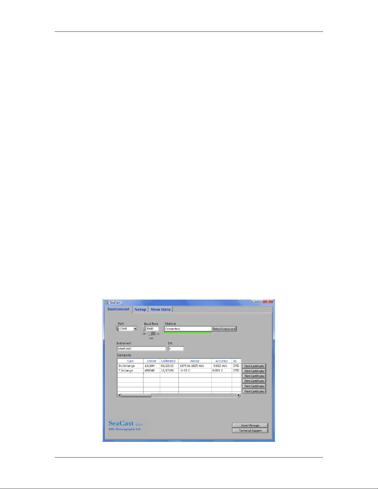
Selecting an Instrument for Configuration ............................................. 5
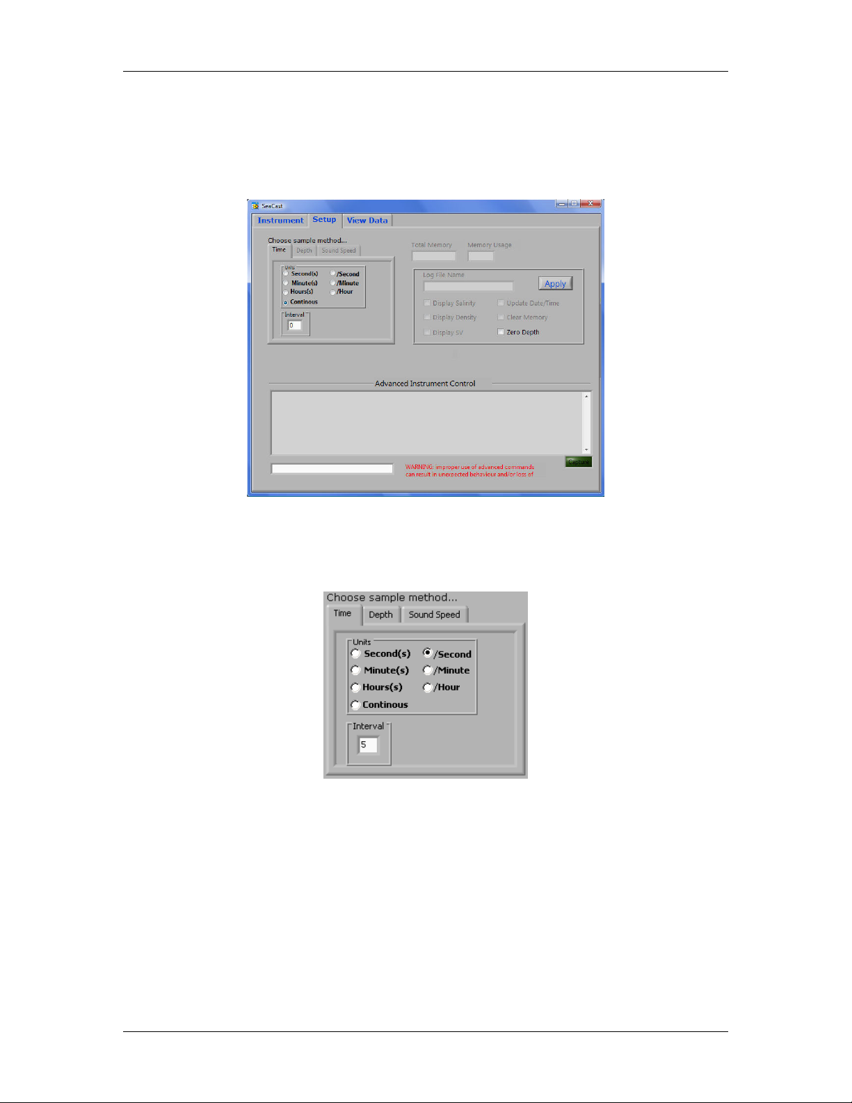
Configuring the Selected Instrument...................................................... 7
Configuring Sampling Parameters with HyperTerminal ............................ 8
Monitoring Real Time Data ........................................................................ 8
Post-Deployment Procedures ...................................................................... 9
Configuring the Instrument for Data on Power Up................................... 10
Disabling Data on Power Up..................................................................... 10
Maintaining the Instrument........................................................................... 11
Periodic Maintenance................................................................................ 11
Communications ........................................................................................... 11
PC Settings ................................................................................................ 11
Output Formats.......................................................................................... 12
Customer Support ......................................................................................... 16
Troubleshooting......................................................................................... 16
AML Oceanographic Contact Info............................................................ 18
Appendices.................................................................................................... 19
Commands................................................................................................. 19
Technical Specifications............................................................................ 20
Warranty .................................................................................................... 22
Wiring Diagram......................................................................................... 23
RS-232 Communications...................................................................... 23
RS-485 Communications...................................................................... 24
Mechanical Drawings................................................................................ 25

User Manual for AML Oceanographic’s Smart SV&T
2
General Description of the Instrument
The AML Oceanographic Smart SV&T is a high speed, high resolution, high accuracy instrument
for measuring sound velocity and temperature in water. The Smart SV&T provides real-time sound
velocity data in meters per second and temperature data in Celsius when connected to a computer
and DC power supply. Optionally, the Smart SV can be equipped with SV•Xchange™ and
T•Xchange™, field swappable sensors.
Which Manual do I Start With?
AML Oceanographic instruments may be shipped with several manuals:
•An instrument manual (ie. This Smart SV&T manual) which provides an overview on how
to use and maintain the instrument;
•A software manual (ie. The SeaCast manual) which provides instructions on how to use
the software to configure the instrument and review instrument data; and
•An SV•Xchange™ manual (for those instruments that have been SV•Xchange™ enabled)
which provides an overview on how to install and maintain SV•Xchange™ sensors.
•A T•Xchange™ manual (for those instruments that have been T•Xchange™ enabled)
which provides an overview on how to install and maintain T•Xchange™ sensors.
If you are configuring an instrument for field use or lab test, we recommend you begin with the
SeaCast software manual.
If you are focussed on instrument maintenance, we recommend you read this instrument manual.
If you wish to swap an Xchange™ sensor, we recommend you read the appropriate Xchange™
sensor manual.

User Manual for AML Oceanographic’s Smart SV&T
3
Shipping & Receiving
Receiving an Instrument
When an instrument is received at a new location it is prudent to perform the following steps to
ensure the instrument is capable of performing when required.
•Check the shipping container for signs of damage. This could indicate damage to the
instrument inside.
•The shipping package should include all of the following items
oSmart SV&T instrument
oData/Power cable
oCD with Manuals
•Check for damage
oCheck the cable for slices or gouges
oCheck the connector for corrosion in the sockets and salt deposits
oCheck the pressure case for dents and scrapes
oCheck the sensors for cracks, bends or dents
•If fitted with Xchange™ sensors ensure the blue retaining rings are tight. They should be
within 1 mm of the pressure case endcap.
•Connect the instrument to a computer and a DC power supply between 6.5 and 26 volts
using the data cable. Launch SeaCast or SmartTalk and use the Monitor button to start
the flow of data from the instrument.
oPlace the instrument in fresh water ensuring no bubbles are trapped on the SV
transducer or reflector plates. The instrument should return sound speed readings
in agreement with the chart below.
oThe temperature sensor can be checked against a thermometer in the water.
Expected sound velocity output in fresh water

User Manual for AML Oceanographic’s Smart SV&T
4
Returning an Instrument to the Factory
•If shipping for repair or recalibration obtain an RMA number from the service centre.
•Perform all the steps listed above for Receiving
•Pack the instrument in its original shipping box, if possible, to prevent damage during
shipping
An RMA number can be requested using any of the following contact options:
Service Department:
Email: service@AMLoceanographic.com
Phone: 1-250-656-0771
Fax: 1-250-655-3655
Website:
http://www.AMLoceanographic.com
Customer Portal:
RMA requests may also be submitted through the customer portal on the AML Oceanographic
website.
To access the Customer Portal, please navigate to the ‘Support’ button, located on the top right
hand side of AML Oceanographic home page, select the ‘Customer Centre’ from the options on the
drop down menu and follow the instructions provided.
Mailing and Shipping Address:
AML Oceanographic.
2071 Malaview Ave.
Sidney, BC, Canada
V8L 5X6

User Manual for AML Oceanographic’s Smart SV&T
5
Using the Instrument
Pre-Deployment Procedures
•4 to 6 weeks ahead
oUse the receiving checklist to verify the instrument is in good working order
oVerify the calibration is valid for the duration of the deployment. If it is not, ship the
instrument or Xchange sensors back to an authorized service centre for re-
calibration, or request an Xchange sensor replacement.
oLubricate the connector with silicone spray
•Before leaving the jetty
oConnect the instrument to a computer and power supply using the data cable
oPlace the instrument in fresh water ensuring no bubbles are trapped on the SV
transducer or reflector plates. The instrument should return sound speed readings
in agreement with the chart on page 3.
Configuring Sampling Parameters using SeaCast
AML Oceanographic’s SeaCast application software greatly simplifies the process of setting up an
instrument to collect data. SeaCast does not require instrument configuration files and is able to
generate copies of sensor calibration certificates on demand.
Full details on the instrument configuration process can be found in the SeaCast manual. Below
please find a quick summary of that process:
Selecting an Instrument for Configuration
On the Instrument Tab, the first row of fields ‘Port’, ‘Baud Rate’ and ‘Status’ control and display the
communications with the instrument.

User Manual for AML Oceanographic’s Smart SV&T
6
The ‘Port’ field allows the user to select the port to which the instrument is connected.
If uncertain about the port the user can check the ports in the Device Manager or
Hardware Manager found in the control panel in the Windows operating system. The
‘Refresh’ selection at the bottom of the list allows the user to force a new detection of
available ports. This is useful if a USB connection is made after SeaCast is launched.
The ‘Baud Rate’ field is used to select the baud rate the user wishes to use while
communicating to the instrument. Lower baud rates allow longer cables to be used if
using RS-232/485/422. Higher baud rates shorten the data transfer times. Choose
38,400 baud whenever possible.
If an instrument is set to autobaud (default setting) it will detect the baud rate chosen in SeaCast
and communicate at that baud rate. If the baud rate is changed in SeaCast the power to the
instrument must be cycled to re-establish communications at the new baud rate.
Some instruments are set up to communicate at fixed baud
rates. In this case the baud rate in SeaCast must be set to the
same baud rate as the instrument. If the instrument baud rate
is unknown, the ‘Scan’ switch below the ‘Baud Rate’ field can
be used to have SeaCast cycle through all the baud rates to try to detect the instrument baud rate.
The “Status” field shows the status of the communications with the
instrument. The green light indicates that communications have been
established with the instrument. During the identification process,
SeaCast is determining the type and serial number of the instrument
and any connected sensors. During the settings process, SeaCast is
determining the latest sampling and logging settings that were
programmed into the instrument. When all the required handshaking
has been completed, the ‘Status’ field will show “Connected” and the
user may now use the instrument.
The Detect Instrument button forces SeaCast to re-detect and re-identify the
instrument and its sensors.

User Manual for AML Oceanographic’s Smart SV&T
7
Configuring the Selected Instrument
After the instrument has been detected by SeaCast, select the Setup tab at the top of the SeaCast
window.
The box in the upper left of the Setup page controls the sampling of the instrument. The Smart
SV&T can be programmed to sample at various sampling rates (ie. sample 25 times per second,
10 times per hour, every 5 seconds, etc.)

User Manual for AML Oceanographic’s Smart SV&T
8
Configuring Sampling Parameters with HyperTerminal
Instruments can also be configured for deployment using HyperTerminal or other terminal
emulation programs. As with SeaCast, communications with the instrument must be established.
The following steps must be completed by issuing text commands.
Please consult the Commands section of the Appendix for full syntax details on how to issue
commands. The following are typical commands issued using HyperTerminal:
•S (scan, sample 1 sound velocity reading)
•M (monitor, sample at the programmed sampling rate)
•SET S 2/S (set the sample rate to two per second)
•SET S 1M (set the sample rate to 1 minute)
•SET DETECT A7 (set 10 autobaud attempts then default to 38400 baud)
•SET STARTUP MONITOR (set the instrument to monitor on power up)
•SET STARTUP PROMPT (set the instrument to wait for a command on power up)
Monitoring Real Time Data
•Ensure the pre-deployment procedures have been done.
•Ensure that the sampling rate desired has been selected.
•Plug the data/power cable into the instrument. If you power the instrument over a long
cable, please note the following:
oThe longer the cable the higher the voltage drop on the cable. The voltage drop
on a standard AML Oceanographic cable, with a Smart SV&T, is about 1 volt per
100m of cable while sampling, 2 volts per 100m for Xchange enabled instruments.
oThe instrument’s minimum voltage is 6.5 volts
oThe voltage at the instrument, while sampling, must be above this level for the
instrument to operate
oThe instrument’s maximum voltage is 26 volts
•Lower the instrument until it is just submerged. Keep the instrument at this depth for 2
minutes prior to beginning the cast. This allows the sensors time to wet and the pressure
case to shed heat. The wetting time for an SV.Xchange enabled instrument is 5 seconds.
•Begin monitoring data using SeaCast or HyperTerminal.

User Manual for AML Oceanographic’s Smart SV&T
9
Post-Deployment Procedures
•When the instrument is pulled from the water it should be rinsed in fresh water
•Dry the area around the connectors with a clean cloth or compressed air prior to
disconnecting the cable
•Remove the shorting plug or cable.
•Dry the instrument and stow it, preferably in the shipping container for protection.

User Manual for AML Oceanographic’s Smart SV&T
10
Configuring the Instrument for Data on Power Up
Perform the following steps:
•Open a terminal emulation program, such as HyperTerminal, and ensure the serial port
has been selected in the program.
•Connect the instrument to the computer using the data/power cable supplied with the
instrument.
•Connect the power leads on the cable to a 12V DC power supply or battery.
•Using the terminal emulation program issue the following commands to the instrument:
oSET STARTUP NOHEADER (disables the power up header information)
oSET STARTUP MONITOR (enable data output on power up)
oSET DETECT 07 (set fixed 38400 baudrate)
oSET SAMPLE RATE 10/S (set the desired sampling rate)
•Turn off the power to the instrument.
•Turn on the power to the instrument.
Disabling Data on Power Up
Perform the following steps:
•Open a terminal emulation program, such as HyperTerminal, and ensure the serial port
has been selected in the program. If the instrument has been set to a specific Baud rate
with the SET DETECT command the terminal emulation program must be configured for
that baud rate.
•Connect the instrument to the computer using the data/power cable supplied with the
instrument.
•Connect the power leads on the cable to a 12V DC power supply or battery.
•Turn off the power to the instrument.
•Hold down the ‘Enter’ key.
•Turn on the power to the instrument.
•After several seconds release the ‘Enter’ key. This will interrupt the data on power up
mode for this power cycle.
•Using the terminal emulation program issue the following commands to the instrument:
oSET STARTUP HEADER (enables the power up header information)
oSET STARTUP PROMPT (disable data output on power up)
oSET DETECT A7 (set 10 autobaud attempts then default to 38400 baud)
oSET SAMPLE RATE 10/S (selects the desired sampling rate)
•Turn off the power to the instrument.

User Manual for AML Oceanographic’s Smart SV&T
11
Maintaining the Instrument
Periodic Maintenance
Periodic maintenance will prolong the life of the instrument. The following is recommended:
•If the instrument is very dirty or oily use warm soapy water and allow the instrument to
soak before cleaning with a rag or soft brush. Rinse with fresh water.
•Before each use
oCheck the tightness of swappable sensors
oCheck for nicks and cuts on the cable
•After each use
oClean and rinse the instrument using fresh water
oDry and safely store the instrument
•Monthly
oLubricate the connector contacts with a silicone spray
oLubricate the retainer rings and o-rings with silicone grease
•Yearly
oSend the instrument, or Xchange sensors, to a service centre for diagnostics and
re-calibration
•Long term storage preparation
oEnsure the instrument has been thoroughly cleaned and dried.
oRemove all Xchange sensors from the instrument and dry the connectors.
oLubricate the instrument and Xchange sensor connector contacts with a silicone
spray.
oLubricate the retainer rings and o-rings with silicone grease.
oInstall connector and sensor blanking plugs in the instrument.
Communications
PC Settings
The Smart SV&T will communicate via RS-232 ASCII unless configured otherwise at the time of
purchase. The computer to which the instrument is connected must be set up as follows:
•8 data bits
•No parity
•1 stop bit
•No hardware handshaking
•Baud rate of 600, 1200, 2400, 4800, 9600, 19,200 or 38,400 baud
After power up, the Smart SV&T will wait for an ASCII carriage return. The instrument will
automatically detect the baud rate unless specifically programmed for a fixed baud rate.

User Manual for AML Oceanographic’s Smart SV&T
12
Output Formats
Standard Smart SV&T
Power-up header output
On power up the Smart SV&T will output a header identifying the instrument, followed by a prompt.
Smart Sv&T Version 4.08 SN:8882
AML Oceanographic Ltd.
>
The power up header can be disabled and enabled using the following commands:
SET STARTUP NOHEADER
SET STARTUP HEADER
Data output formats
The data output format for the standard Smart SV&T is sound velocity followed by temperature.
The characters are space, 4 digits, decimal point, 2 digits, space, sign (space for positive, - for
negative), 2 digits, decimal point, 3 digits. The sound velocity output is in units of m/s and the
temperature output is in Celsius. The number of sound velocity decimal places can be changed by
entering TALK 1 mode, using the SET FORMAT command, then pressing Ctrl C to exit the TALK 1
mode, then cycling the instrument power. The number of temperature decimal places can be
changed by entering TALK 2 mode, using the SET FORMAT command, then pressing Ctrl C to exit
the TALK 2 mode, then cycling the instrument power.
Scan output (SCAN then Enter or S then Enter)
>scan
1482.58 17.798
>s
1482.56 17.794
>
Monitor output (Monitor then Enter or M then Enter)
>m
1482.57 17.647
1482.57 17.648
1482.57 17.648
1482.57 17.647
1482.57 17.647
1482.57 17.648
...
Changing the output order
The sound velocity and temperature output order can be reversed by using the EMULATE
command. In this case emulating the old Smart SV&T output format.
>set emu svt
Emulating an Sv&T
>s
17.708 1482.74
>set emu off
Emulation mode is disabled
>s
1482.76 17.709
>

User Manual for AML Oceanographic’s Smart SV&T
13
Display options output (DIS O then Enter)
>dis o
[Instrument]
Type=Smart Sv&T
EmulationMode=disabled
UseCustomHeader=yes
SN=8882
Firmware=V4.08
SampleUnits=continuous
SampleInterval=0
PressureInc=0.00
SoundInc=0.00
TestLog=test.raw
Date=01/01/00
Time=00:00:00
MemorySize=0.0 MB
MemoryUsed=0.0 MB
DisplayTime=no
DisplayDate=no
DisplaySalinity=no
DisplayDensity=no
DisplaySoundVelocity=no
DisplayBattery=no
RelayMode=auto detection
RealtimeLogging=no
LoggingTimeout=0
StartupDelay=10
DisplayHeader=yes
StartupMode=prompt
CharacterReception=yes
LoggingBreakMode=no
DetectionMode=A3
BatteryACoefficient=+3.500000E-01
BatteryBCoefficient=+2.500000E-02
ShutDownVoltage=8.0
WarningVoltage=9.0
PressureOffset=0.00
UsePressureOffset=no
SoundVelocityThreshold=1375.00
DelimterMode=Space
SensorDetectionMode=Once
Traceability=no
SkipPowerOff=no
[Slot 1]
SensorName=Micro SV
BoardSN=00911
SensorSN1=
CalDate1=01/14/10
CalBy1=DTD
CalRange1=1375-1600
CalAccuracy1=0.05 m/s
SensorSN2=
CalDate2=00/00/00
CalBy2=
CalRange2=
CalAccuracy2=
[Slot 2]
SensorName=Micro T
BoardSN=00912
SensorSN1=400021
CalDate1=01/08/10
CalBy1=DTD
CalRange1=-2 to 32 C
CalAccuracy1=0.002 C

User Manual for AML Oceanographic’s Smart SV&T
14
SensorSN2=
CalDate2=00/00/00
CalBy2=
CalRange2=
CalAccuracy2=
>
Xchange enabled Smart SV&T
Power-up header output
On power up the Smart SV&T will output a header identifying the instrument, followed by a prompt.
Smart.X Version 4.08 SN:8882
AML Oceanographic Ltd.
>
The power up header can be disabled and enabled using the following commands:
SET STARTUP NOHEADER
SET STARTUP HEADER
Data output formats
The data output format for the Xchange Smart SV&T is sound velocity followed by temperature.
The characters are space, 4 digits, decimal point, 3 digits, space, sign (space for positive, - for
negative), 2 digits, decimal point, 3 digits. The sound velocity output is in units of m/s and the
temperature output is in Celsius. The number of sound velocity decimal places can be changed by
entering TALK 1 mode, using the SET SV FORMAT command, then pressing Ctrl C to exit the
TALK 1 mode, then cycling the instrument power. The number of temperature decimal places can
be changed by entering TALK 2 mode, using the SET TEMP FORMAT command, then pressing
Ctrl C to exit the TALK 2 mode, then cycling the instrument power.
Scan output (SCAN then Enter or S then Enter)
>s
1483.103 17.822
>
Monitor output (Monitor then Enter or M then Enter)
>m
1483.129 17.831
1483.126 17.830
1483.130 17.830
1483.132 17.830
1483.116 17.831
...
Changing the output order
The sound velocity and temperature output order can be reversed by using the EMULATE
command. In this case emulating the old Smart SV&T output format.
>set emu svt
Emulating an Sv&T
>s
17.704 1482.741
>set emu off
Emulation mode is disabled
>s
1482.762 17.709
>

User Manual for AML Oceanographic’s Smart SV&T
15
Display options output (DIS O then Enter)
The DISPLAY OPTIONS command provides an easy way to see all the configuration information
for the instrument and associated sensors. The Smart SV&T with Xchange display options output
format is as follows:
>dis opt
[Instrument]
Type=Smart.X
EmulationMode=disabled
UseCustomHeader=yes
SN=8882
Firmware=V4.08
SampleUnits=continuous
SampleInterval=0
PressureInc=0.00
SoundInc=0.00
TestLog=test.raw
Date=01/01/00
Time=00:00:00
MemorySize=0.0 MB
MemoryUsed=0.0 MB
DisplayTime=no
DisplayDate=no
DisplaySalinity=no
DisplayDensity=no
DisplaySoundVelocity=no
DisplayBattery=no
RelayMode=auto detection
RealtimeLogging=no
LoggingTimeout=0
StartupDelay=10
DisplayHeader=yes
StartupMode=prompt
CharacterReception=yes
LoggingBreakMode=no
DetectionMode=A3
BatteryACoefficient=+3.500000E-01
BatteryBCoefficient=+2.500000E-02
ShutDownVoltage=8.0
WarningVoltage=9.0
PressureOffset=0.00
UsePressureOffset=no
SoundVelocityThreshold=1375.00
DelimterMode=Space
SensorDetectionMode=Once
Traceability=no
SkipPowerOff=no
[Slot 1]
SensorName=SV.X Sensor SN 131194 01/22/10
BoardSN=01234
[Slot 2]
SensorName=P-T.Xchange T.X SN 400048 11/17/09
BoardSN=65535
>

User Manual for AML Oceanographic’s Smart SV&T
16
Customer Support
Troubleshooting
Instrument fails to communicate:
•Check the cables
oIs the data power cable connected to the instrument and computer?
oIf using a cable other than an AML Oceanographic cable, it should be configured
as a null modem cable
oIf using multiple cable lengths, the extensions should not be configured as null
modem cables
oAre there any cuts in the cable?
•Is power applied? Power should be 6.5 to 26 volts DC at 110 mA, 200 mA for Xchange
enabled instruments.
•If using external power over a long cable, check the voltage drop over the cable. Measure
the voltage across a ¼ watt, 59Ω, resistor across pins 1 and 4 of the cable. The voltage
must be above 6.5 volts. Use a 33Ωresistor for exchange enabled instruments.
•Are the communication settings in the program used on the computer correct?
oComm port selection
o8 bits
o1 stop bit
oNo parity
oNo hardware handshaking
oBaud rate between 2400 and 38,400 baud
•Are the communication settings in the instrument correct?
oWas the instrument set to a fixed baud rate last time? If so, the user must use that
baud rate to resume communications
oWas the instrument set to RX OFF last time? If so, a carriage return must be sent
to the instrument immediately after power is applied to interrupt this mode. This is
most easily done by holding down the enter key as soon as power is applied.
Character reception on power up can be re-enabled using the SET RXON
command.
oWas the instrument set to monitor on power up mode? If so, a carriage return
must be sent to the instrument immediately after power is applied to interrupt this
mode. To disable monitoring on power up use the SET STARTUP PROMPT
command.
•Is the connector damaged?

User Manual for AML Oceanographic’s Smart SV&T
17
Instrument generates noisy SV data:
•Are there bubbles on the SV sensor?
•Is the SV sensor clean?
•Is there noise on the power supply? Transient noise on the power supply lines should be
less than 20 mV in amplitude.
•Is there noise on the com lines? Transient noise on the communication lines should be
less than 20 mV in amplitude.
•Are there close sources of electromagnetic interference, such as switching power supplies,
inverters, radios, electric motors with brushes? Separate the sensor and data/power cable
from the interference source.
Instrument generates noisy temperature data:
•Is there noise on the power supply? Transient noise on the power supply lines should be
less than 20 mV in amplitude.
•Is there noise on the com lines? Transient noise on the communication lines should be
less than 20 mV in amplitude.
•Are there close sources of electromagnetic interference, such as switching power supplies,
inverters, radios, electric motors with brushes? Separate the sensor and data/power cable
from the interference source.

User Manual for AML Oceanographic’s Smart SV&T
18
AML Oceanographic Contact Info
Service:
To request an RMA or technical support
Email: service@AMLoceanographic.com
Phone: 1-250-656-0771
Fax: 1-250-655-3655
Sales:
For all general sales inquiries
Email: sales@AMLoceanographic.com
Phone: 1-250-656-0771
Fax: 1-250-655-3655
Website:
http://www.AMLoceanographic.com
Customer Portal:
The Customer Portal allows AML Oceanographic customers to download calibration certificates
and other related instrument documentation, view instrument details and diagnostic reports. It also
allows AML Oceanographic customers to gather technical documentation, troubleshooting guides
etc. RMA requests or technical support queries may also be submitted through the portal
To access the Customer Portal, please navigate to the ‘Support’ button, located on the top right
hand side of AML Oceanographic home page, select the ‘Customer Centre’ from the options on the
drop down menu and follow the instructions provided.
Mailing and Shipping Address:
AML Oceanographic.
2071 Malaview Ave.
Sidney, BC, Canada
V8L 5X6

User Manual for AML Oceanographic’s Smart SV&T
19
Appendices
Commands
Some commands are only available on instruments enabled with Xchange™ sensors.
Command Short form
Uses
TALK
mode
Xchange
only Description
DISPLAY OPTIONS DIS OPT
Displays a listing of the instrument configuration and
settings
SCAN
S
Takes a single data sample
MONITOR M
Repeatedly takes samples at the p
rogrammed sampling
rate. This can be interrupted by pressing the ENTER
key.
VERSION
V
Displays the instrument header information
SET SAMPLE RATE n/u
SET S C
SET S 10/s
SET S 2m
Changes the sampling rate in numbers and units. I.e.
Continuous (25 per second), 10 per sec, 2 minutes, 1
hour, etc. The range is 25/s to 1 hour.
DISPLAY SAMPLE RATE
DIS S
Displays the current sampling rate
SET SV UNITS x/x SET SV U x/x
•
Set the sound velocity units. Options are m/s and ft/s
SET STARTUP HEADER
SET ST
H
Enables the instrument header on power up
SET STARTUP NOHEADER
SET ST NOH
Disables the instrument header on power up
SET STARTUP MONITOR
SET ST M
Instrument will start monitoring on power up.
SET STARTUP SCAN SET ST S
Instrument will take one
scan on power up and then
return a prompt.
SET STARTUP PROMPT SET ST P
Instrument will issue a prompt on power up and wait for
a command
DISPLAY STARTUP
DIS ST
Displays the current startup conditions
DISPLAY COEFFICIENTS
DIS C
Displays the curren
t calibration coefficients
SET DETECT ab SET DET ab
Set the baudrate auto detection parameters. a is the
number of detection attempts (0=fixed baudrate, 1= 1
attempt, up to F=15 attempts) and b is the baudrate to
default to if autobauding is not successful (1=600,
2=1200, 3=2400, 4=4800, 5=9600, 6=19200, 7=38400,
8=57600 SV.X only, 9=115200 SV.X only)
SET EMU SVT
SET EMU SVT
Changes the output channel order to T then SV
SET EMU OFF
SET EMU OFF
Returns the output channel order to SV then T
DISPLAY DETECT DIS DET
•
Displays the current autobaud detection parameters
SET SV FORMAT nn SET SV F nn •
Sets the number of digits before and after the decimal
point.
SET TEMP FORMAT nn SET TEM F nn •
Sets the number of digits before and after the decimal
point.
SET AVERAGE n SET AV n ••
Sets the number of scans used for each
SV
sample
output. Options should be 1, 2, 4, 8. (Default value is 1)
SET ECHO
SET EC
Enables the echoing of characters
SET NOECHO
SET NOEC
Disables the echoing of characters
SET RXON
SET RXON
Enables the reception of commands at next power up
SET RXOFF SET RXOF
Disables reception of characters at next power up. To
exit the RXOFF mode, hold down the carriage return
key and power up the unit, then from the prompt, issue
the SET RXON command.
TALK 1 TALK 1 •
Talk mode 1. Enters direct communications with the
sensor board in slot 1. Use Cntrl C to exit talk mode.
Table of contents