AMP MAKER N5X Instructions for use

1www.ampmaker.com
This build guide describes how to build the
N5X guitar amplier kit from Amp Maker.
The N5X is the successor to the very
popular SE-5a 'British Overdrive' amplier
kit. The circuit is almost identical, but
with some of the most popular
modifications added as standard:
1. VCB for getting power valve
distortion at lower room volumes
2. Switchable boost: None/Bright/Fat
3. Bypassable tone stack for more gain
4. More power valve options:
EL84/6V6/6L6/EL34/etc
5. All popular speaker impedances
covered: 4/8/16 ohms
This build guide assumes you have
an N5X kit from Amp Maker (above), but
you can also follow the instructions if you
want to build the amp with parts that you
have sourced yourself. If so, you'll have to
adjust the build to cater for dierences in
the parts you have (transformer taps,
etc). If you're building with your own
chassis, or a donor chassis, I strongly
suggest you follow the general parts
layout shown in the guide to help avoid
noise/hum/etc issues from a sub-
optimal layout.
I've tried to make this build guide as
easy as possible to follow and that means
that it contains a lot of detail, tips and
practical advice to help things go
smoothly. If you have any feedback -
please let me know.
AMP MAKER
N5X
Construction guide

2 N5X Construction guide
Kit contents
Your N5X amplier kit contains all of the electronics and hardware parts needed to make a great-
sounding valve amplier. Before jumping in, clear a space on your workbench and unpack all of the
components. Start by checking the Kit contents listing below. Look through the electronic components
R1 1M/0.5W
R2 15k/0.5W
R3 1.5k/0.5W
R4 100k/0.5W
R5 47k/0.5W
R6 47k/0.5W
R7 470k/0.5W
R8 15k/0.5W
R9 820r/0.5W
R10 100k/0.5W
R11 47k/0.5W
R12 47k/0.5W
R13 100k/0.5W
R14 1M/0.5W
R15 5.6k/0.5W
R16 150r/1W
R17 470r/3W
R18 2k2/1W
R19 10k/0.5W
R20 100r/0.5W
R21 1k/1W
R22 100k/3W
R23 10r/5W
R24 100k/0.5W
R25 100k/0.5W
R26 100k/3W
C1 1uF/25V
C2 47uF/25V
C3 22nF/400V
C4 1uF/25V
C5 47uF/25V
C6 500pF/500V
C7 22nF/400V
C8 22nF/400V
C9 22nF/25V
C10 47uF/25V
C11 47uF/35V
C12 22uF/350V
C13 22uF/350V
C14 47uF/350V
C15 47uF/350V
C16 22uF/350V
C17 22uF/350V
VR1 470K log (Gain) + knob
VR2 220k lin (Treble) + knob
VR3 1M log (Bass) + knob
VR4 22k lin (Middle) + knob
VR5 1M log (Master) + knob
VR6 1M lin (Power) + knob
D1 UF4007
D2 12.1V/1.3W zener
D3 UF4007
D4 UF4007
Q1 MOSFET + insulator
S1 DPDT centre-o (Boost)
S2 SPST (Bypass)
S3 DPST (On/O)
V1 9-pin socket + shield
V2 9-pin socket + retainer
V3 8-pin socket + clip
T1 Output transformer
T2 Power transformer
L1 Neon (220-240V)
J1 1/4" mono jack socket
J2 1/4" mono jack socket
J3 1/4" mono jack socket
J4 1/4" mono jack socket
J5 IEC chassis plug*
F1 T500mA fuse + holder*
* (integrated)
Wire:
• 30cm of shielded wire
• 3m insulated multi-stranded wire for
green
• 2m insulated multi-stranded wire for
each of blue and red
• 1m insulated multi-stranded wire for
each of black, brown, pink, violet,
and yellow
• 50cm insulated solid wire for each of
black, brown and orange
• 50cm of solid bare wire
• 5cm of heatshrink tubing
• 2 cable ties
Hardware:
• M6 cage nuts x4
• M6 bolts x4
• M6 shakeproof washer x1
• M4 screws x7
• M4 shakeproof washers x7
• M4 nuts x7
• M4 ground lugs x3
• M3 M-F spacer x9
• M3 6mm screws x13
• M3 10mm screws x1
• M3 CS screws x2
• M3 shakeproof washers x25
• M3 nuts x16
• M3 ground lugs x2
• M2.5 nuts x4
• M2.5 shakeproof washers x4
• M2.5 screws x4
• 9.5mm rubber grommets x3
• 6.35mm rubber grommets x2
• 3-way tag-strip x1
Misc:
• Turret board (x2)
• Chassis
• Control panels
• Hole plug

3www.ampmaker.com
3www.ampmaker.com
and check them o. If this is your rst amplier project take a little time to familiarise yourself each type
of component, its shape, size and connections (leads, solder lugs, etc).
Resistors
The Kit contents page lists the resistors rst. Most resistors are too small to have printed values, and
instead the manufacturers use a standard set of colour coded bands to indicate the resistor's value. You
can decipher the code using the Resistor colour codes table below.
For resistors, r = ohms (Ω), k = kilohms (kΩ) and M = megohms (MΩ).
TIP: Depending on the colour of the resistor's body, some colour bands may be tricky to read; dark
green, for example, may appear to be almost black. If in doubt, to avoid any mistakes use your digital
multimeter (DMM) to check the resistance. There's a tolerance in all components, and in the resistors,
values will be within +/- 5% of the specied value, such as 98.2 for the 100 Ohm resistor.
It's also very apparent that a few resistors are bigger than others. The resistor size is related to its
power rating: the smaller ones being rated for a maximum of 0.5W, the slightly larger ones for 1W, the
medium-sized ones for up to 3W and the largest for up to 5W. This will be very apparent when you lay
them out side by side. There's only one value which is present in two ratings - 100k, with the 3W version
being much bigger than the 0.5W version. Resistors do not have a polarity; so it does not matter which
way around they are connected in the circuit.
(Note that supplies of parts do vary over time, and a resistor shown in the build guide may be a
dierent colour to what's supplied in your kit, or it may be printed with a written value instead of colour
bands. If you're in any doubt, get in touch with Amp Maker.)

4 N5X Construction guide
Capacitors
Almost all modern capacitors have their values and ratings printed somewhere on their body. This
written information makes it easy to work out which capacitor is which. (There is a colour coding system
for certain types of small capacitor but none of those are included in this project.)
The rst part of the text is the capacitance value itself. This is shown in units of microFarads (uF),
nanoFarads (nF) or picoFarad (pF). When comparing what you see with the Kit contents list bear in mind
that 1000pF = 1nF = 0.001uF. The smallest caps are the silver mica ones, usually reddish brown or tan in
colour. These may not have a unit printed, but these capacitors are always in the picoFarad range, so
"500 500V" means 500pF.
You'll also see from the printed information that capacitors have a voltage rating. This is a maximum
working voltage for the component, and it's very important. Whereas all of the resistors in your kit are
rated well over the maximum voltage present inside any part of this amplier, it's a dierent story for the
capacitors. They are all specied and rated according to their place in the circuit and the voltages
present in that position.
For example, the large power supply capacitors will be faced with the highest voltages in your amp -
which can be almost 300V. So these capacitors must be rated for at least this voltage; the parts
supplied with your kit are rated at 350V or more (see below). This is plenty. Likewise, there are some
signal caps inside the amplier that are rated at 500V and 630V - more than enough.
Not all capacitors need to be rated at such a high voltage. And it would be very wasteful of money
and space to have every capacitor rated for the full voltage range of the amplier. For example,
capacitor C1 is rated according to its position at the cathode of the ECC83 preamp valve, and it never
undergoes a high voltage - perhaps 2V at most. So any rating of 25V or more is ne (I usually supply
100V as they are far more readily available, and still quite small). Capacitors may have voltage ratings
higher than specied above (depending on supplies).

5www.ampmaker.com
Some capacitors have a polarity - a positive terminal and a negative terminal. In this amplier kit,
the blue/black electrolytic capacitors are all polarised. Look closely at the printing and you will see that
one of the leads on each of these capacitors is marked by a minus sign (-). This is often contained within
an arrow printed on the side of the capacitor, where the direction shows the negative terminal.
Potentiometers
Variable resistors in the form of potentiometers (also known as pots) are supplied for the amplier's main
controls. In all cases, the value and type is printed somewhere on the pot's body. Suppliers dier in how
they mark the value/type. For some, it is stamped on the back of the pot, and for others it's printed on
the front of the pot. On the second type, you can only see the value when you view the pot from the
shaft of the pot - you can just make out 'B1M' in the picture below.
The text will also indicate the pot type. You may see 'Lin' or 'Log'. If you don't see either of these, look
for the a code letter next to the pot's value: A1M means 1M log; B22k means 22k lin.
The pots have three lugs, and it's important to know which is which, so the diagram below shows
the numbering convention. I always refer to the pot's lugs with reference to the back of the pots and
with the lugs uppermost - as that's always the side you will look at when you are soldering.
Diodes and MOSFET
These are the kit's semiconductors, and they are all used in the power supply (not the signal path, which
is 100 percent valve). There are two types of diode, with the zener diode being much smaller and
reddish/pinkish in colour.

6 N5X Construction guide
Look closely and you will see that the diodes all have a small band around one end: silver on the
black diodes and black on the pink zener diode. This shows the polarity of the diode - the banded end is
the cathode. To do its job properly and safely, a diode MUST be tted the correct way around as shown in
the build guide diagrams that follow.
WARNING! The MOSFET needs special handling, so do not take it out of its anti-static bag (silver or
pink plastic instead of clear) until you are ready to use it. For now, just check that it's present in your kit.
Turret boards
The N5X uses two turret boards, the smaller one is for the power supply and the larger one for the
amplier's signal path. Most of the smaller components will be mounted to the turrets on these boards.

7www.ampmaker.com
Other components
The rest of the kit contents list spells out the sockets, switches, etc you use to make up the rest of the
circuit. Check the contents against the list and let Amp Maker know of any problems or missing parts.
Wire and Hardware
There's also a bag of wire with several types and colours of wire: solid, stranded, insulated, bare and
shielded. Don't worry, there's more than enough cable to build the amplier. In addition, a bag of
hardware includes all of the fasteners you need to mount the parts to the chassis.
Chassis and control panels
These aluminium parts should be pretty obvious! :) The control panels are both anodised, so they won't
show any ngerprints from handling. The chassis is not anodised, so once you have removed the plastic
covering the outer surface, it will be easily marked by handling. Of course, it's harmless and out of sight
once the chassis is installed in your cabinet.

8 N5X Construction guide
N5X schematic
The page opposite shows the N5X's full-size schematic. This diagram shows all of the component values
added and with numbered lugs for all o-board components. All components are numbered on the
schematic (R1, C3, D4, etc), so that you can relate this schematic to your Kit contents listing and the
turret board layouts.
Do I need to be able to read a schematic?
This is a very common question for new amp builders who may feel intimidated by a diagram covered in
rather mysterious electronic symbols. The short answer is 'no'; the rest of the build guide shows exactly
where everything goes and how it's all connected.
But it is a good idea to become familiar with schematics. They are the denitive guide to how any
circuit works. From a schematic, you can follow the signal path, check the connections of components,
and so on. An experienced amp builder or amp tech can even look at a schematic and work out
everything from there, with no other documentation.
As always, if you break a complex structure up into smaller parts, it's a lot easier to understand. If
this is your rst build, you will nd that the following description will help you understand the whole
schematic of the N5X amplier as a group of smaller circuits, each with their own job.
Block diagram
The main schematic looks very busy, and is crammed with information. It's a lot easier to understand if
you think of the circuit as a number of modules. This diagram shows them colour coded.

9www.ampmaker.com

10 N5X Construction guide
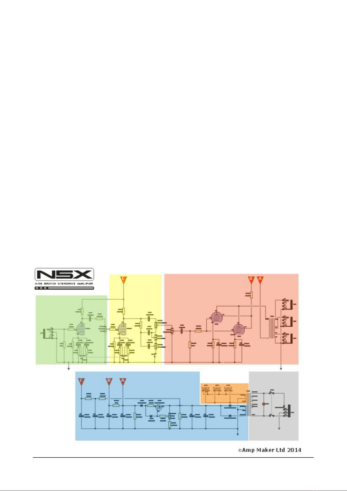
Along the top, there's your guitar signal path from left to right:
* green box = guitar input, rst amplication stage and Gain control
* yellow box = second amplication stage and TMB tone controls
* red box = Master volume and power stage
Along the bottom, there's the power supply, with the mains entering at bottom right:
* grey box = mains-side circuit
* orange box = heater supply for the valves
* blue box = power supply with VCB
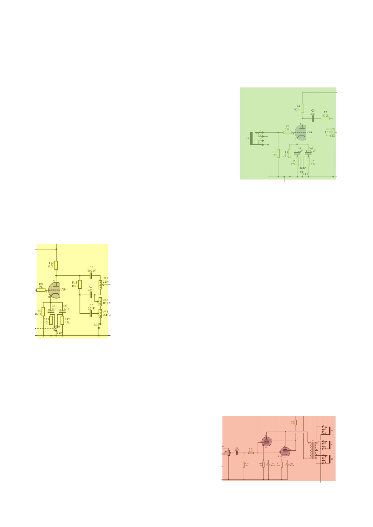
First amplication stage
The guitar input socket is shown at the top left, and it feeds into the
light green shaded section. This is the rst stage of the amplier and
it uses one half of the ECC83 preamp valve (V1a) to amplify the low-
level guitar signal.
The resistors and capacitors around V1a set the way that it works
- how much current ows at idle and what EQ is applied to the signal passed along to the next stage.
There's also one half of the Boost switch (S1a) here - it controls which is any capacitors are used to add
an extra boost to part of the guitar signal.
The nal part of this section of the circuit includes the Gain pot, which controls how much of this
boosted signal is fed into the second stage.
Second amplication stage
The guitar signal - still fairly clean so far - is fed into the second part of the
amp (shaded in light yellow in the block diagram). This uses the other half of
the ECC83 preamp valve, V1b. Many of the components are similar to the rst
stage, and there's the other half of the Boost switch, here, too. If the Gain
control is set high, the incoming signal will overdrive this second amplication
stage to create some preamp distortion.
The output of this stage then runs through a network of resistors,
capacitors and pots that allow you to control the treble, middle and bass
frequencies of the signal that will be passed along to the power valve. This is a
'lossy' tone stack, meaning that in order to adjust the TMB frequencies, it must throw away part of the
amplied signal. With the Bypass switch (S2) enabled, however, you can choose to have the full output
of this stage passed along to the power valve.
Power stage
The reddish shaded section shows the power stage, which includes the Master volume control, the
power valve and the output transformer. The Master volume is the simplest part - a pot that lets you dial
in how much signal the power valve receives. Low settings for
cleaner tones, and at higher settings you can overdrive this
valve to get maximum distortion.
The N5X includes a 'noval' socket for EL84 valves (like the
SE-5a), but also has an octal power valve socket, V3. So you can
plug in a 6V6/6L6/EL34/etc instead of the EL84. These bigger
valves have dierent overdrive characteristics and tones, and

11www.ampmaker.com
you can experiment to nd your own tone.
The power valve works with high voltages and low currents, and the output transformer transforms
this into a low-voltage, high-current signal that's suitable for driving the speaker (which you connect to
any of the jack sockets at the top right of the diagram).
And that's all there is to the signal path of the amplier! An amplier with a simple signal path like
this remains very dynamic - responding well to changes in your picking style and/or pedals - and allows
you to dial in a surprising amount of distortion.
Mains circuit
The signal path runs from left to right at the top of the diagram, but
the power supply runs right to left at the bottom of the diagram. So
the rst stage is the mains circuit, with the IEC mains adapter at
the bottom right.
The light grey section shows the part of the amp that operates
directly from the mains supply. It includes the fuse, On/O switch
and a neon indicator. Just as important is the connection of the
Earth wire from the IEC lead to the amp's metal chassis. Via these
components, the mains is fed to the mains side of the power
transformer, which has a range of inputs to suit your local mains
voltage: 100V, 120V, 220V, 230V and 240V.
Valve heater supply
The mains transformer has two outputs, known as secondary windings. One of these supplies the valves
with a low voltage to (literally) warm them up. This is the heater supply - shown in light orange in this
diagram.
The heater is the part of the valve's internal electrodes that
glows dull-orange when an amplier is switched on. Once it has
warmed up, a valve can start to conduct the guitar signal, but
not before. This is why there's always a small delay between
switching an amplier on and being able to hear any sound.
High-voltage supply
The power transformer also provides a high-voltage AC output in addition to the heater supply. This
high-voltage winding is shown in the light blue section of the block diagram.
It feeds into some diodes which work together to turn the AC voltage into the DC voltage required
by the valves. The large power supply capacitors and resistors lter out mains hum and pass the DC
voltage on to each of the amplication stages (shown by the red triangles).
In the N5X, there's a Variable Voltage Regulator (VCB) circuit - shown here as the darker blue block.
You can use the VCB pot to dial down the voltage supplied to the power stage. There's just one good
reason to do this:
it lets you have
power-valve
distortion at any
room volume,
from 0W and 5W.

12 N5X Construction guide
Chassis assembly
Getting started
My #1 suggestion in building an amp kit has always been: do a dry run rst. So before diving straight in
and doing all of the stu that looks interesting and exciting, do a few test assemblies to see how things
go together. This will help you avoid problems that you could have foreseen. trust me, there's nothing
worse than having to undo dozens of screws or desolder some components to add an item you
overlooked.
That said, in this build guide I will try to describe the most methodical way to build the amplier. So
hopefully you can avoid any such problem. :) The image opposite shows a fully annotated chassis with
all hardware installed in position. You can follow this directly and/or use the extra tips in the rest of this
page.
Initial hardware
A few items become hard to access once other components are installed so do these rst. Start with the
two M4 ground lugs shown circled here in red, making sure to bend the ground lug so that the soldering
hole will be accessible later.
In each case, use an M4 screw from the outside of the chassis, then the ground lug inside the
chassis, then a shakeproof washer and then the M4 nut to secure it.

13www.ampmaker.com

14 N5X Construction guide
Turret board mountings
Next, add the hardware for mounting the two turret boards. There are nine 3mm holes altogether, shown
here. In each case, add a 6mm M3 screw from the outside, then a shakeproof washer on the inside, then
one of the M-F spacers to secure it in place.
Now check that both of the turret boards mount on these spacers. There's a little tolerance ('wriggle
room') built into the mounting dimensions, so if necessary you can loosen one of the M-F spacers and
adjust it slightly in its hole. At this point, do not x the turret boards in the chassis. We'll get to that later.
Other lightweight hardware
In general, it's a hell of a lot easier to handle a chassis-assembly job if you keep it as light as possible for
as long as possible. For this reason, add the other lightweight parts rst and the heavy transformers
later. Here's the simpler stu, in no particular order:
* V1 valve socket using M2.5 hardware
* V2 valve socket and retaining clip using M2.5 hardware
* V3 valve socket and retaining clip using M3 hardware (6mm screw)
* 3-way tagstrip using M4 hardware

15www.ampmaker.com
In each case, insert the screw from the outside and don't forget the shakeproof washers (remember that
ampliers are subjected to a lot of vibration). Make sure to choose the correct size washer for the screw
- don't use the M3 washers with M2.5 hardware, or you'll run out when you need them!
Then add the hole cover to the unused hole between V1 and V2 and insert the ve rubber grommets.
There are two sizes, but it's not possible to get them mixed up. Now attach the four M6 cagenuts to the
outside (top) of the chassis anges.
Rear panel and components
Just four sockets and four sets of hardware to do here. But it's
easier to add your country's mains voltage and the fuse
information before you mount the rear panel. Use a permanent
marker pen to write in these two pieces of information in the
box provided at the right end of the panel. Your mains voltage
will be one of 100/120/220/230/240V and the fuse value will be
"T500mA".
There's also a pre-printed box for you to personalise your
amplier build in the centre of the panel. Write in your own
details here.
Now add the rear panel and secure it in place with M4
hardware with ground lug at the far right end of the chassis
(when viewed from the inside), and M4 hardware (without a
ground lug) at the far left.
Then add the three speaker output sockets, orientating
them so that the solder lugs are all facing out of the chassis for
soldering later. Add the IEC mains socket and secure it with M3
hardware (using the countersunk screws).
Front panel and controls
The N5X's front panel is held in place by the main amplier controls: six pots, three switches, one lamp
and one socket. However, for now, install only the six pots to allow easy access for other parts later.
(Keep J1, S1, S2, S3 and L1 on one side.) When installing the pots, there are a few things to bear in mind:
1) trim the black nylon shaft (B) so that it's about 8mm long - use a junior hacksaw, Dremel with cutting
wheel or similar
2) use BOTH plain washers on the inside of the chassis...
3) ...to allow the small locating tab (A) to t in the small holes
in the front of the chassis (bend it slightly, if necessary)
One minor thing to bear in mind: the order of the pots
along N5X panel isn't sequential! The pots are numbered
according to the schematic - as they should be - but it's
obviously conventional to put the Middle pot (VR4) between
the Treble pot (VR2) and the Bass pot (VR3) on the front
panel. :)
TIP: Double-check that you have the single 1M lin pot in the VR6 position for the Power control for the
VCB circuit. The two 1M log pots are for Bass (VR3) and Master (VR5).

16 N5X Construction guide
Mounting the transformers
Add the output transformer, T1, orientating it to so that the speaker wires (orange, yellow, green and
grey) from its secondary winding pass through the grommet closest to the back panel, with the brown
and red wires of the primary passing through the other grommet. Secure this transformer with M4
hardware.
Now add the power transformer, T2, on the outside of the chassis. Start by removing the M6 nut to
allow the M6 bolt to pass through the hole in the chassis. Then rotate the toroid so that the wires are in
roughly the correct positions. For the N5X amplier layout, the thicker green wires of the heater supply
go through the rubber grommet that's closest to the centre of the chassis, with the brown + yellow +
brown wires of the high-voltage supply going the centre grommet and the six wires of the mains-side
primary going through the grommet closest to the edge of the chassis.
This is a bit tricky and rather ddly. :) Take your time and insert the wires rst and then gently lower
the toroid down on to the chassis. Make sure that the second rubber pad sits properly between the
bottom of the toroid and the chassis surface. The toroid is secured by adding the M6 shakeproof washer
on the inside of the chassis and then the M6 nut.

17www.ampmaker.com
Building the power supply
In the N5X, we build and test the power supply (including the smaller turret board and the VCB circuit)
before building the rest of the amplier. Start by gathering up the turret board and the following
components:
* R20
* R22
* R23
* R24
* R25
* R26
* C13
* C16
* C17
* D1
* D2
* D3
* D4
* the bare bus wire
The rst job is to add two lengths of bare bus wire to the top and bottom row of turrets, as shown above.
Solder each wire to the side of the turret that it passes, eight solder joints in all.
TIP: Amp builders have their own technique but if you're not sure, you can weave the wire around the
turrets (as shown above), and at each end wrap the wire around the last turret.
Add power supply components
Now trim and solder the components to the board, as shown in the diagram below. A few notes to help
you:
1) For diodes D3 and D4, it’s best to solder them to the sides of the turrets. This leaves the turret hole
available for you to add the high voltage supply wires.
2) Pay attention to the orientation of the following components: C13, C16, C17, D1, D2, D3 and D4. Make
sure they are connected as shown in this diagram. (If you've ever made an Amp Maker kit, pay special
attention, because this
set of three capacitors
are the opposite way
around to kits such as
the WF-55, SE-5a, PP-18,
etc!)
Now mount this
turret board in the
chassis. Use an M3
shakeproof washer and
M3 nut for each of the
four mounting points.

18 N5X Construction guide
Initial power supply wiring
There are three sets of wires from the power
transformer. The rst two sets connect as follows:
1) Green + black + green wires to the 3-way
tagstrip close to the rst rubber grommet. Trim
each wire and solder it to the relevant solder tag.
2) Brown + yellow + brown wires to the turret
board as shown here.
For each of these wires, it’s best to tin the end
with solder and then bend it to create a ‘hook’ that
you can place around each turret shaft - shown
above in step-by-step form). Use needle-nose
pliers to crimp the hook around the shaft of the
turret and then solder it into place.
Then connect the VCB circuit's Power
control (VR6) to the turret board with three
wires as shown here. Solder lugs 2 and 3,
but leave lug 1 unsoldered for the moment.
As usual with hand-wired amplier layouts
- in general it's best to keep wires as short
as possible and routed directly. Avoid
unnecessarily long wires.

19www.ampmaker.com
Mains-side wiring
With the turret board properly installed, you can add the On/O switch (S3) and the neon indicator (L1)
to the front panel. (For clarity, the front and back panels are shown here as if they have been folded
down, although in reality they are at the usual 90 degrees to the bottom of the chassis.)
The rst job is to add three wires to the IEC socket: a short green wire to connect the Earth lug
directly to the grounding lug next to the IEC socket, and a brown and blue wire to the Live and Neutral
lugs. Run the brown and blue wires along the side of the chassis to the On/O switch, twisting them
together and solder them to the top pair of lugs on the On/O switch.
Then connect the six remaining wires from the power
transformer. First, choose the correct two wires for your mains
supply:
* 100V = white and blue
* 120V = grey and blue
* 220V = brown and blue
* 230V = purple and blue
* 240V = orange and blue
Run these two wires over to the On/O switch and trim and
connect them, one to each of the switch's centre lugs. Don't
solder them just yet, however. (The diagram to the right shows
the orange and blue wires in use for a 240V connection for UK,
Australia, etc.)
You now have
four wires left over,
the colours will
depend on those you
chose for your mains
supply of course.
Run these four wires to the four turrets on the right of the
board. Trim them to length and solder them now. (If you move
to another country with a dierent mains supply, you can
alter this wiring in the future.)

20 N5X Construction guide
Wiring the neon indicator
Prepare the neon indicator for soldering by gently prising the two solder
tags away from the black plastic - use a thin-bladed screwdriver. This
makes it easier to add a wire to each tag's solder hole.
Find the thin brown wire in the wire pack - the type that has just a
single solid strand (instead of the thicker multi-stranded type). Solder two
wires to the neon indicator, one to each lug and then twist them gently
together and run them across to the centre lugs of the On/O switch. Connect one to each lug and now
you can solder all four wires in place.
Adding the MOSFET
Next, you add the MOSFET. But before we even touch that, here are
some vital safety points:
1) MOSFET devices can be damaged by static, including small charges
that build up on your body. If you're susceptible to static shocks, then
pay special attention - places with low humidity (air conditioning in use)
can be tricky. Here's a site with a useful guide on static: http://
www.wikihow.com/Remove-Static-Electricity - each time before I pick
up a MOSFET, I touch something that I know is grounded (a radiator, another amplier chassis that's
plugged into the mains, etc) to discharge any static.
2) The #1 tip here is: keep handling to a minimum. Pick it up only when you need it, and do the whole
process as a single operation.
3) This MOSFET carries a high voltage on its metal mounting tab so you MUST properly insulate it from
the chassis. There's a sticky SILPAD supplied with the kit for this
reason.
MOSFETs such as these are modern devices, designed for insertion in
PCBs. For hand-wired layouts, it's a good idea to tweak their
connection pins to make them easier to connect. Start by creating a
solder lug for each of the three legs of the MOSFET. Use needle-nose
pliers to carefully bend the legs upwards and round to make a ring or
hook that you can more easily solder to.
Now add the sticky SILPAD to the underside of the
MOSFET, making sure that the holes line up and the whole
of the MOSFET's underside is covered. Then mount it to the
chassis using M3 hardware (using the 10mm M3 screw).
There are two holes here; use the one that allows the
MOSFET to clear the power supply board and orientate the
MOSFET so that the 'lugs' are closest to the board. Do not
overtighten the nut.
Finally, add the three connecting wires between the
MOSFET and the board and Power level pot.
Other AMP MAKER Amplifier manuals