6 WF-55 Construction guide
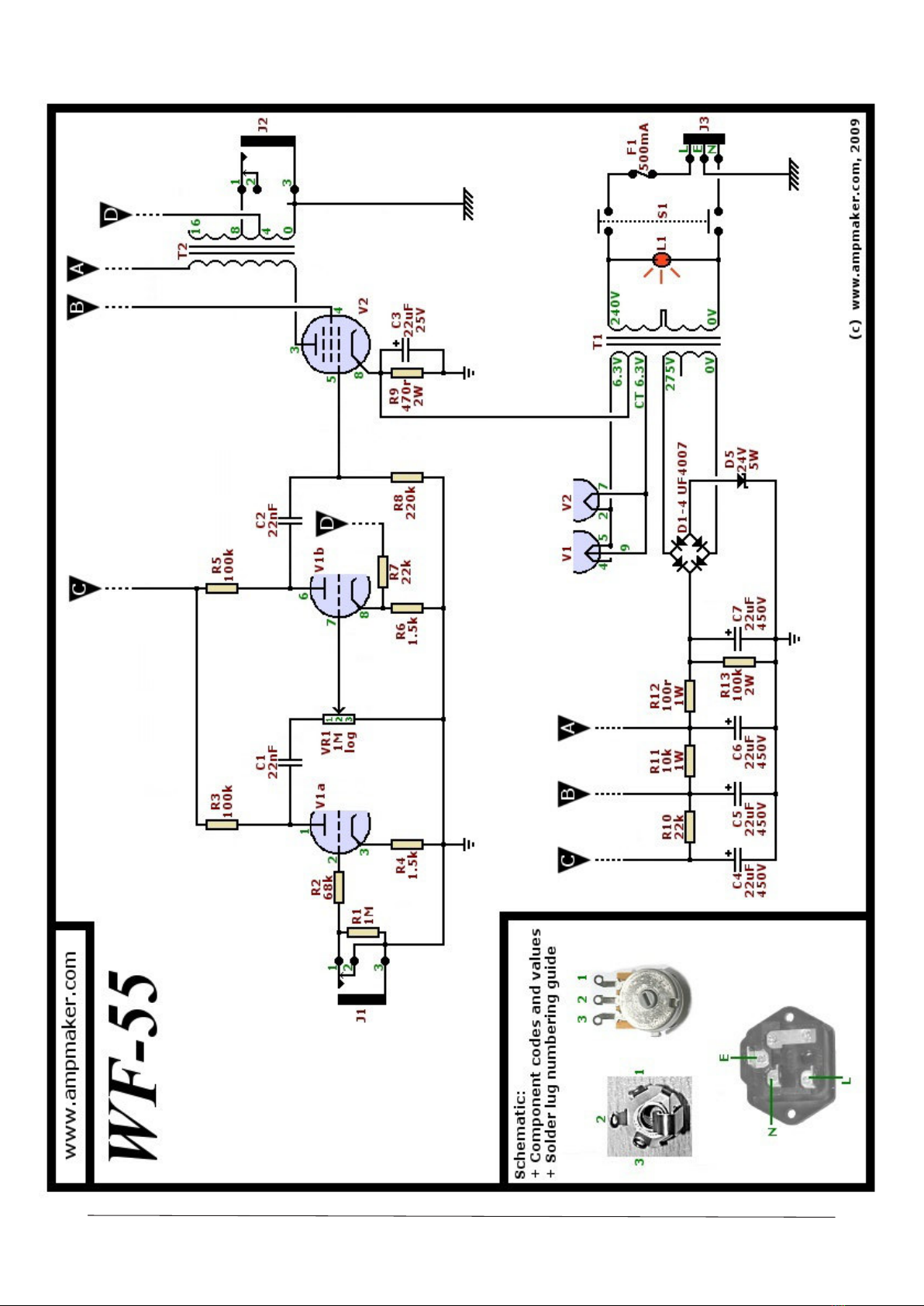
Schematic
All components are numbered on the
schematic (R1, C3, D4, etc), so that you
can relate this schematic to the Kit
contents listing (earlier) and the turret
board layout (later).
It's the specic values in the circuit
that combine to make the amplier
work and sound the way that it does.
For example, capacitor C1 does two
jobs. The rst is to block the high DC
voltage (supplied to the rst stage of
the preamp via resistor R3 and R10)
from feeding into the input of the
second amplication stage; any value
of capacitor would work for this task.
The second job that the capacitor does
is to control the amount of lower
frequencies in the amplied guitar
signal that are passed from the rst
amplication stage to the second -
higher values allow more bass through,
lower values allow less.
Build now, tweak later
It's the ease with which you can alter
individual components in an amp
circuit that makes hand-wired amps so
appealing. For example, you can swap
in components with the same ratings
but dierent values to change the
response of part of the circuit. This is
the real beauty of building your own
amp - you can ne-tune it to the tone
you like.
It's best to get your amp up and
running rst, by sticking to the
components specied on the
schematic and supplied with your kit.
There are many ways to tweak the
vintage 5F1 Champ circuit, and you can
decide if you want to try that when the
amplier is working properly as
standard. While it may be tempting to
leap ahead and increase the bass
frequencies by using other capacitor
values, for example, doing this in the
wrong part of amp circuit may
inadvertently cause your amp's
distortion tone to become 'muddy'.
Solder lug numbering
Look closely at the schematic and you'll see numbering for
the solder lugs of certain components. For example, the jack
sockets, pot and mains input socket each have 3 solder lugs.
To help avoid confusion, your schematic
includes numbers next to each
connection for these components, and
at the bottom left of the schematic
there's also an annotated photo
reference for each.
Valve sockets have even more
solder lugs. There are nine solder lugs for
the preamp valve, numbered clockwise,
starting at the gap (below). The second
and larger valve socket is an 8-pin type
(for the 6V6 power valve). It has a small
keying 'notch' in the central round hole -
which you can just see here at the 3-
o'clock position. The pin numbers (1 to 8)
are moulded in the underside next to
each solder lug, working clockwise
from this keying notch. However,
they're almost impossible to see in
anything other than the brightest
light, so I've added annotations here
for reference.
The picture opposite shows the WF-55's full schematic - the same
circuit as the block diagram and with all component values added
and with numbered lugs for all o-board components.