manuals.online logo
Brands
  1. Home
  2. •
  3. Brands
  4. •
  5. Ampetronic
  6. •
  7. Intercom System
  8. •
  9. Ampetronic HLS-1A System manual

Ampetronic HLS-1A System manual

HLS-1A
Hearing Loop System - Driver Module
Installation Handbook
www.ampetronic.com
Contents Copyright © Ampetronic Ltd 2016-21. All rights reserved.
UP17931-2
Handbook Contents
• Safety
• Installation & Connection
• Specication
• Warranty Information
• Declaration of conformity
Box Contents
• 1 x HLS-1A
• 1 x O-Ring
• 2 x Lid screw (M3x8)
• 1 x Wago Terminal Tool
• 1 x Handbook (this document)
This symbol is used to alert the user to important
operating or maintenance instructions.
The Lightning bolt triangle is used to alert the user
to the risk of electric shock.
SAFETY
1. It is important to read these instructions, and to follow them.
2. Keep this instruction manual in an accessible place.
3. No user serviceable parts. Refer all servicing to qualied personnel.
4. Clean only with a dry cloth. Cleaning uids may a󰀨ect the equipment.
5. Install in accordance with the manufacturer’s instructions.
6. Do not install this equipment near any heat sources such as radiators, heating vents or other
apparatus that produces heat.
7. Refer all servicing to qualied personnel. Servicing is required when the apparatus has been
damaged in any way, such as a power supply cord or plug is damaged, liquid has been spilled
or objects have fallen into the apparatus, the apparatus has been exposed to any rain or
moisture, does not operate normally or has been dropped.
8. WARNING – To reduce the risk of re or electric shock, do not expose this apparatus to
rain or moisture. The apparatus shall not be exposed to dripping or splashing and no
objects lled with liquids, such as vases, shall be placed on the apparatus.
TO PREVENT ELECTRIC SHOCK REFER
SERVICING TO QUALIFIED PERSONNEL
Ampetronic HLS-1A HandbookPage 1
Ampetronic HLS-1A Handbook Page 2
Installation and Connection
1. The unit can be securely mounted using the 2 x M4 mounting holes.
2. Connect loop feed cable to the loop clamp connector (see diagram).
3. Connect the low impedance speaker cable to input 1.
4. Use a screened cable <1m to connect an electret microphone to input 2.
5. Observing correct polarity, connect the DC power supply and apply power (see diagram). The
power indicator will illuminate.
6. With the input signal on, increase the Input control until the green AGC LED illuminates with a
normal signal.
7. Adjust the Output control until the amber Current LED is illuminated with signal peaks.
8. Use an Ampetronic FSM to test the system and adjust as required to be consistent with the
requirements of the latest IEC 60118-4 Standard. Use the MLC control to adjust for high
frequency loss.
9. Wind the cable through the restraint posts as shown in the image below.
10.Fit the O-ring to hold the cables in place.
11.Fit the lid using 2 screws, posting the cables through the mousehole.
Fault Conditions
Overheating: The amplier will output max rated sine current for 1 minute into rated load. After
this period an internal protection mechanism will attenuate the output.
Overcurrent / Overvoltage: The amplier will shutdown if its capabilities are exceeded for a
short period. The amplier will resume normal operation when operated within the normal
parameters.
Input 2
Screw Adjust
Input 2
Mic Input
Input 1
Speaker
Line Input
Loop Current
Screw Adjust
MLC
Screw Adjust
Power LED
AGC LED
Loop Current LED
Loop
Clamp
Connector
Input 1
Screw Adjust
Mounting
Hole
Mounting
Hole
Cable
Restraint
DC Power
Ampetronic HLS-1A HandbookPage 3
Technical Specifications According to IEC 62489-1:2014 Standard
PARAMETER VALUE
Max area coverage 45m2
Power supply range 12-24V DC
Fuse PTC resettable 1.5A
Current consumption (12V DC)
Continuous pink noise 240mA DC
Quiescent 50mA DC
Short term peak 1200mA DC
Input 1 (Speaker Line level)
Rated source EMF (sensitivity) -16dBu
Overload +22dBu
Input Isolation 1500V
Rated Source Impedance 1.8kΩ di󰀨erential
Input 2 (Unbalaced Mic level)
Rated source EMF (sensitivity) -55dBu
Overload -23dBu
Electret Bias Voltage 12V through 11kΩ
Rated Source Impedance 10kΩ
Current (into rated load) Sine 1kHz >3ARMS
Pink Noise >1.5ARMS
Frequency response (0.6ARMS) 100Hz to 5kHz ± 1.5dB
Compliance voltage 4.2VRMS
Weight 243g
Dimensions 124 x 77 x 16mm
Connectors Clamp Terminals
Environmental IP22, -30°C to +75°C, <90% relative humidity
Typical heat dissipation <3W
WARRANTY
This product carries a ve year parts and labour warranty from date of shipment from Ampetronic. To qualify
for the ve year warranty, the product must be registered at www.ampetronic.co (products/warranty), without
which the warranty will be valid for two years only.
The warranty could be invalidated if the instructions in this handbook are not followed correctly, or if the unit
is misused in any way.
DECLARATION OF CONFORMITY
Manufacturer: Ampetronic Ltd.
Unit 2, Trentside Business Village, Farndon Road, Newark, Nottinghamshire,
NG24 4XB, United Kingdom.
Declares that the product:
Description: Induction Loop Driver
Type name: HLS-1A
Conforms to the following Directive(s) and Norm(s):
Directive 2004/108/EC
EMC: EN55103-1 : 2009+A1:2012 Emission (E1-5)
EN55103-2 : 2009 Immunity (E1-5)
Directive 2006/95/EC
Safety: EN60065 : 2014
Directive 2011/65/EU RoHS
Date: March 2016
J.R. Pieters
Managing Director, Ampetronic Ltd.

Other Ampetronic Intercom System manuals

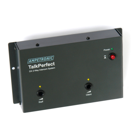
Ampetronic TalkPerfect DX User manual

Ampetronic

Ampetronic TalkPerfect DX User manual

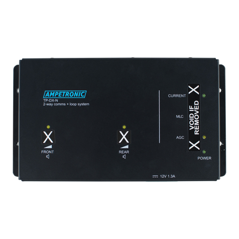
Ampetronic TP-DX-N User manual

Ampetronic

Ampetronic TP-DX-N User manual

Popular Intercom System manuals by other brands

Elvox 6611/F operating instructions

Elvox

Elvox 6611/F operating instructions

ViziT UKP-12-1 Operating	 instruction

ViziT

ViziT UKP-12-1 Operating instruction

Viking E-30 Technical practice

Viking

Viking E-30 Technical practice

Aiphone AI-SSV instructions

Aiphone

Aiphone AI-SSV instructions

Intercom System HFX-700B Quick reference guide

Intercom System

Intercom System HFX-700B Quick reference guide

Aiphone MY-2CD Specifications

Aiphone

Aiphone MY-2CD Specifications

Bpt OPHERA US Instructions for use and installation

Bpt

Bpt OPHERA US Instructions for use and installation

Fermax VIDEO CONTROL KIT manual

Fermax

Fermax VIDEO CONTROL KIT manual

RTS IFB 4030-M User instructions

RTS

RTS IFB 4030-M User instructions

JeaTone Smart tuya Quick Start Guideline

JeaTone

JeaTone Smart tuya Quick Start Guideline

Toa VS-900 Programmer's guide

Toa

Toa VS-900 Programmer's guide

Escene IS750 Quick reference guide

Escene

Escene IS750 Quick reference guide

Vidos Duo Series user manual

Vidos

Vidos Duo Series user manual

Competition SAC5B-CK Operation and installation guide

Competition

Competition SAC5B-CK Operation and installation guide

Midland BTX1 PRO S Instruction guide

Midland

Midland BTX1 PRO S Instruction guide

Tech Works CI-ODC-1 Quick reference guide

Tech Works

Tech Works CI-ODC-1 Quick reference guide

SSS Siedle Siedle Scope S 850-0 operating instructions

SSS Siedle

SSS Siedle Siedle Scope S 850-0 operating instructions

Valcom V-9936A user guide

Valcom

Valcom V-9936A user guide

manuals.online logo
manuals.online logoBrands
  • About & Mission
  • Contact us
  • Privacy Policy
  • Terms and Conditions

Copyright 2025 Manuals.Online. All Rights Reserved.