Amphenol Excel Mate CC User manual

1
AMPHENOL PCD SHENZHEN
EXCEL|MATE CC
Electric car charging coupler
www.amphenolpcd.com.cn

1
CONTENT
PRODUCT INTRODUCTION .............……….....................……..........………...………...... 2
SPECIFICATIONS ...……………………………………………....................….…...................... 3
CHARGING MODES CLASSIFICATION …………….......……….…........………...………....... 4
INSERT ARRANGEMENT ...………....................….....….....………...………....……….……... 5
CIRCUIT DIAGRAM: VEHICLE SIDE ..........…………………….....………...………....…......... 6
CIRCUIT DIAGRAM: CHARGING STAKE SIDE ......................................................... 7
AC COUPLER DIMENSIONS …………………….......………............................................. 8
PANEL MOUNTING DIMENSIONS ...………….…………................…….......................... 9
INSERT ARRANGEMENT (DC) ............................................................................... 10
DC CIRCUIT DIAGRAM ...…………………………………….....………...……….....……….…........ 11
80A DC COUPLER DIMENSIONS ………………………………….....………...………....………… 12
125A TO 250A DC COUPLER DIMENSIONS …………………….....………...….................. 13
PRODUCT SERIES SUMMARY …………………..........................................…............... 14
HOW TO ORDER .................................................................................................. 15
PART NUMBERS ..........................................………...……….....……….........………....... 16
VEHICLE INLET - 90° RIGHT-ANGLE .....………...……….....………...……….....………........ 17
DC VEHICLE INLET (SMALL SIZE) - FRONT MOUNTED .....………...……….....…........... 18

2
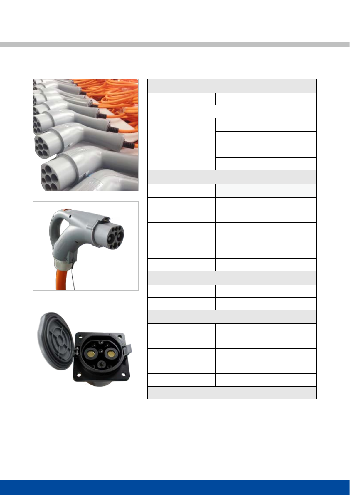
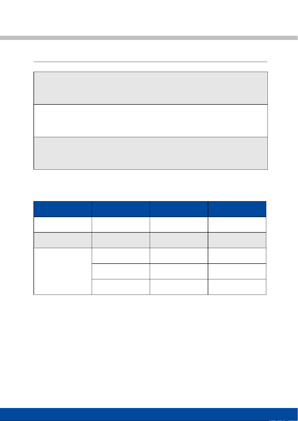
PRODUCT INTRODUCTION
Amphenol PCD Shenzhen charging couplers are all compliant with GB/T 20234.1/2/3-2015 standards.
User-friendly, easy to unmate, IP 55 (mated).
High current contacts with Amphenol Radsok Technology.
3
MECHANICAL
Mating cycles ≥ 10000 cycles
Connector (in mated condition) retention force:
AC coupler
Unmating 100N Max
Mating 200N Min
DC coupler Unmating 140N Max
Mating 200N Min
ELECTRICAL
AC (R6) DC (R12)
Rated current 63A Max 250A Max
Rated voltage 250V/440V AC 750V/1000V DC
Contact resistance 0.5mΩ Max 0.2mΩ Max
Insulation resistance >100MΩ
(DC500V)
>100MΩ
(DC500V)
ENVIRONMENTAL
Protection degree IP55 (mated)
Ambient temperature -30°C to 50°C
MATERIAL
Shell Thermoplastic
Contact Copper alloy, silver or nickel plating
Insert Thermoplastic
Sealing gasket Rubber or silicon rubber
Insulator inammability UL94V0
4
CHARGING MODES CLASSIFICATION
RATED CURRENT AND VOLTAGE FOR DIFFERENT CHARGING MODES
Charging Mode Couple Type Rated Voltage Rated Current
2AC coupler 250V AC 16A
3AC coupler 250V/440V AC 32A
4
DC coupler 750V/1000V DC 80A
DC coupler 750V/1000V DC 125A
DC coupler 750V/1000V DC 250A
Remarks:
All types of charging modes should be connected with residual current operated circuit-breakers and overflow
protective device. Residual current operated circuit-breakers should be compliant with GB/T 16916.1 or GB/T 16917.1
requirements.
CHARGING MODE 2:
When connecting electric vehicle to AC network, the plug and socket-outlet at power supply side shall comply with
requirements of GB 2099.1. Phase line, neutral line and protective earth conductor shall be used at power supply side
and the residual current operated circuit breaker shall be used at power supply side.
CHARGING MODE 3:
When connecting electric vehicle to AC network, the plug and socket-outlet at power supply side shall comply with
requirements of GB 2099.1. Phase line, neutral line and protective earth conductor shall be used at power supply side
and in-cable control box is installed in the charging connection cable.
CHARGING MODE 4:
When connecting electric vehicle to AC network, use special power supply equipment. Directly connect the electric
vehicle with AC network and install control guide device on the special power supply equipment.
5
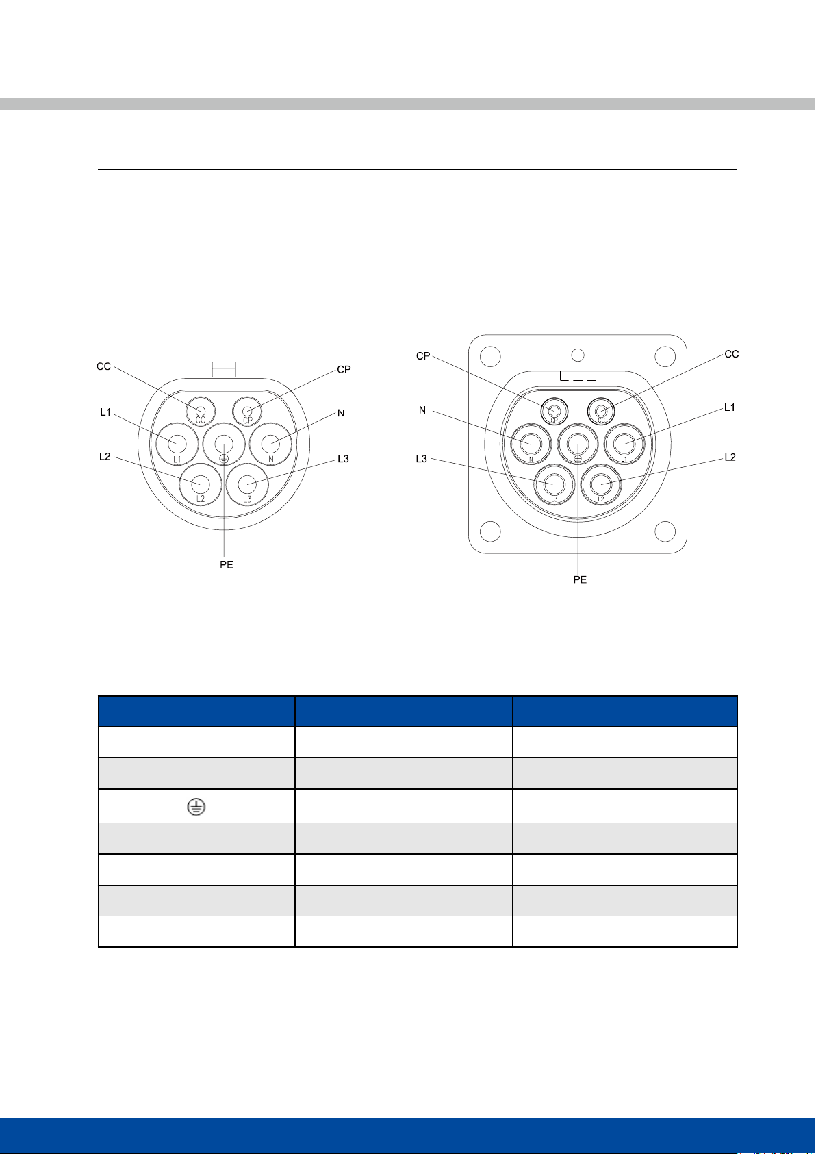
INSERT ARRANGEMENT
CONFIGURATION
AC Coupler insert arrangement
National standard
Contacts Number & Function Rated Voltage & Current Function
L1 250V/440V 16/32A AC power
N 250V/440V 16/32A Neutral
- PE, connect charging stake and
vehicle chassis ground
CC 30V 2A Charging conrmation
CP 30V 2A Control conrmation
L2 - Back up contact
L3 - Back up contact
VEHICLE CONNECTOR VEHICLE INLET

6
CIRCUIT DIAGRAM: VEHICLE SIDE
VEHICLE CONNECTOR VEHICLE INLET
Mains (L1)
Back up 1 (L2)
Back up 2 (L3)
Neutral (N)
Ground (PE)
Charging conrmation (CC)
Control conrmation (CP)
Mains (L1)
Back up 1 (L2)
Back up 2 (L3)
Neutral (N)
Ground (PE)
Charging conrmation (CC)
Control conrmation (CP)

7
CIRCUIT DIAGRAM: CHARGING STAKE SIDE
PLUG SOCKET-OUTLET
Mains (L1)
Back up 1 (L2)
Back up 2 (L3)
Neutral (N)
Ground (PE)
Charging conrmation (CC)
Control conrmation (CP)
Mains (L1)
Back up 1 (L2)
Back up 2 (L3)
Neutral (N)
Ground (PE)
Charging conrmation (CC)
Control conrmation (CP)

8
PLUG
SOCKET
AC COUPLER DIMENSIONS
VEHICLE CONNECTOR
VEHICLE INLET
CHARGING STAKE PLUG
SOCKET-OUTLET
E-lock
E-lock

9
MOUNTING INSTRUCTIONS
VEHICLE INLET
SOCKET-OUTLET
MOUNTING INSTRUCTION
MOUNTING INSTRUCTION
Panel installation guide
Panel installation guide
Wall
Sealing gasket (selective)
Frange square
Wall
Sealing gasket (selective)
Frange square
E-lock
This manual suits for next models
6
Table of contents
Popular Automobile Accessories manuals by other brands


ULTIMATE SPEED
ULTIMATE SPEED 279746 Assembly and Safety Advice

SSV Works
SSV Works DF-F65 manual

ULTIMATE SPEED
ULTIMATE SPEED CARBON Assembly and Safety Advice

Witter
Witter F174 Fitting instructions

WeatherTech
WeatherTech No-Drill installation instructions

TAUBENREUTHER
TAUBENREUTHER 1-336050 Installation instruction