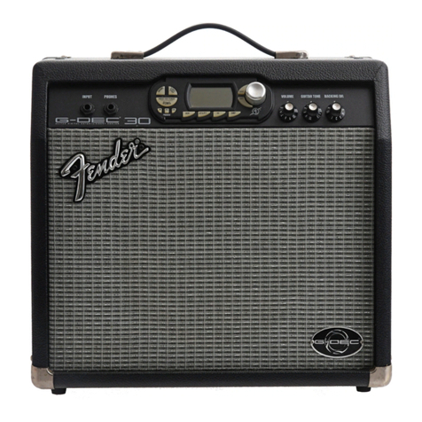
G-DEC®Jr
(This is the model name for warranty claims)
7
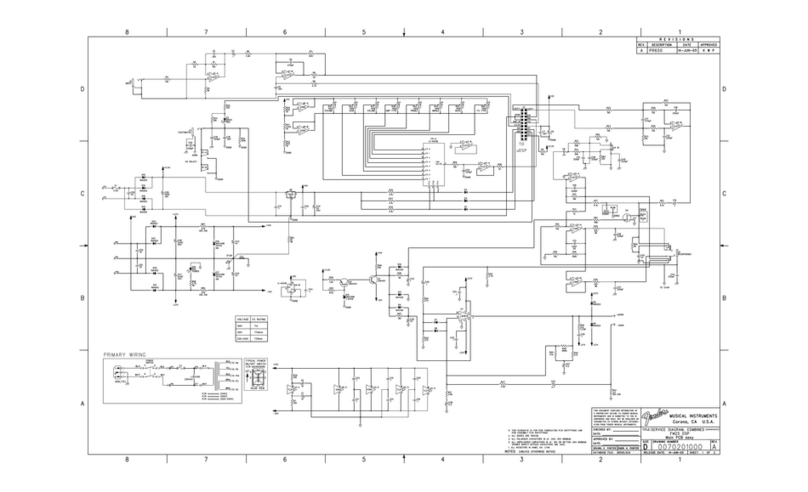
MIDI System
MIDI Input signals from the external MIDI INPUT
Jack (J4) are optically isolated via U22 and sent to
the Rx line of the uDSP UART controller within U10
for processing. When MIDI is selected on the LOOP
Selector, the MIDI signal being received is passed
through to the Tx line of the uDSP UART and to the
MIDI IN of the SAM2195 Dream Synthesizer chip
U20. The SAMP2195 then plays MIDI sounds based
on the commands being sent from the external MIDI
sequence source.
With internal LOOPS selected the external MIDI in-
put is ignored and MIDI IN signals are generated by
the uDSP system under control of the LOOP SE-
LECT and KEY SELECT controls. The rate is
controlled by the TEMPO control.
Audio output from the SAM2195 Dream Synthesizer
chip is mixed in at summing op-amp U2-B via
R50/R54. The audio output of U2-B is mixed in with
the instrument post processed (effects and amp
types added) and Auxiliary Input audio at U2-A.
POWER SUPPLIES
The power transformer secondary windings are con-
nected to the main PCB at P5 through P10.
The +/-20VDC power supplies for the solid-state
power amplifier are derived from the red-yellow-red
secondary of the power transformer via full bridge
rectifiers D4/D5 and D2/D3, and main filter caps C14
and C8. The yellow center tap lead and the system’s
chassis connection are placed between these caps,
making this the system ground star.
The +/-12VDC power supplies for the op-amps are
regulated down from the +/-20 VDC supplies through
dropping resistors R13-14 and Zener Diodes D6 and
D7.
The +11.5VDC power supplies for the Digital circuitry
is derived from the brown-brown secondary of the
power transformer via full bridge rectifiers D15, D16,
D17 and D21 and filter caps C34. This raw supply is
then regulated down to +5VDC by U5 (7805).
The +5VDC supply powers multiplexer U6, Front
Panel LED drivers Q5-Q7 and the D.C. reference
voltage string R41-R43 for the high-low reference
level for front panel potentiometers. The +5V is regu-
lated down to 3.3v and 1.25V via U18 and U17
respectively. The 3.3V and 1.25 V supply power to
the uDSP system components and the MIDI I/F
components including the SAM2195 Dream Chip
U20 and U22 MIDI input opto-isolator. Reset control-
ler U12 monitors the +5V supply and shuts down all
ICs in the event of power loss.
USER INTERFACE
The 4 - 16 position encoders (S2 –S5) for the LOOP,
AMP, KEY and EFFECT SELECT are read via the
port expander U9 and the data sent to the uDSP sys-
tem via the I
2
C interface lines SCL and SDA.
The 4 potentiometers VOLUME(R51), GAIN(R49),
TONE(R44), and TEMPO(R31) generate DC volt-
ages (+1.0V to +4.0V) that are read by the analog
multiplexer U6. IO0-IO3 are the digital control lines
used to multiplex these analog signals which are
sent serially to the system CODEC U13 on the Rin
channel. The LOOP START/STOP button and the
state of the HEADPHONE present signal are read in
a similar manner. The uDSP system reads the state
of these controls and inputs digitally from the CO-
DEC.
The LOOP VOLUME is a conventional analog con-
trol which accepts the MIDI left and right loop audio
signals from the SAM2195 MIDI Synthesizer via the
mixer op-amp U7-B.
