ams AG AS5115 User manual

austriamicrosystems AG
is now
ams AG
The technical content of this austriamicrosystems document is still valid.
Contact information:
Headquarters:
ams AG
Tobelbaderstrasse 30
8141 Unterpremstaetten, Austria
Tel: +43 (0) 3136 500 0
e-Mail: ams_sales@ams.com
Please visit our website at www.ams.com

Revision 1.1, 26.02.2010 Page 1 of 10
www.austriamicrosystems.com
1General Overview
The AS5115 is a contactless rotary enco er sensor for
accurate angular measurement over a full turn of 360º
an over an exten e ambient temperature range of -
40ºC…+150ºC.
Base on an integrate Hall element array, the angular
position of a simple two-pole magnet is translate into
analog output voltages. The angle information is provi e
by means of buffere sine an cosine voltages. This
approach gives maximum flexibility in system esign, as
it can be irectly integrate into existing architectures an
optimize for various applications in terms of spee an
accuracy.
An SSI Interface is implemente for signal path
configurations, as well as a one time programmable
register block (OTP), which allows the customer to a just
the signal path gain for ifferent mechanical constraints
an magnetic fiel s.
2The AS5115 Demoboard
The AS5115 emoboar is a complete rotary enco er system with built-in microcontroller, USB interface, an graphical
LCD isplay. The boar is USB powere or externally supplie with a 9V battery for stan alone operation.
Figure 1: AS5115 Demoboard hardware with mounted mag net knob
Demoboar v1.1 has a itional pull-up resistors at the communication lines. The emoboar v1.2 has a new controller
(C8051F342) implemente an supports up ating of the firmware via bootloa er (please refer to AN5000-
60_FirmwareUpgra e).
3Operating the AS5115 Demoboard
The AS5115 emoboar can be use in several ways:
•A tandalone unit upplied by a 9V battery
Connect a 9V battery to the battery connector on the top right si e of the boar . No other connections are
require .
AS5115
Programmable 360° Magnetic Angle Encoder with
SINE & COSINE Output Signal
AS5115
Demoboard
OPERATION MANUAL
LCD isplay (for stan alone mo e)
AS52
15
output signals connector
an switch
Connector for external
evice
USB connector
to the
PC
(backsi e)
9V battery connector
(stan alone
only
)
SiLabs C8051F
320
microcontroller
(backsi e)
Knob with D5x2.5mm
iametral magnet,
2mm over the
AS5215
ams AG
Technical content still valid

AS5115 Demoboar OPERATIO NAL MANUAL
Revision 1.1, 26.02.2010 Page 2 of 10
www.austriamicrosystems.com
•A tandalone unit upplied by an USB port
Connect the emoboar to a PC using a USB/USB cable (inclu e in emoboar shipment). The boar is
supplie by the 5V supply of the USB port. No other connections are require .
•A input device for the AS5000 Programmer GUI oftware
This configuration uses the same USB har ware connection as mentione above, but a itionally the AS5000
Programmer GUI software is running. The LCD isplay will be turne off an the Angle/Sine/Cosine value will
be isplaye on the PC screen.
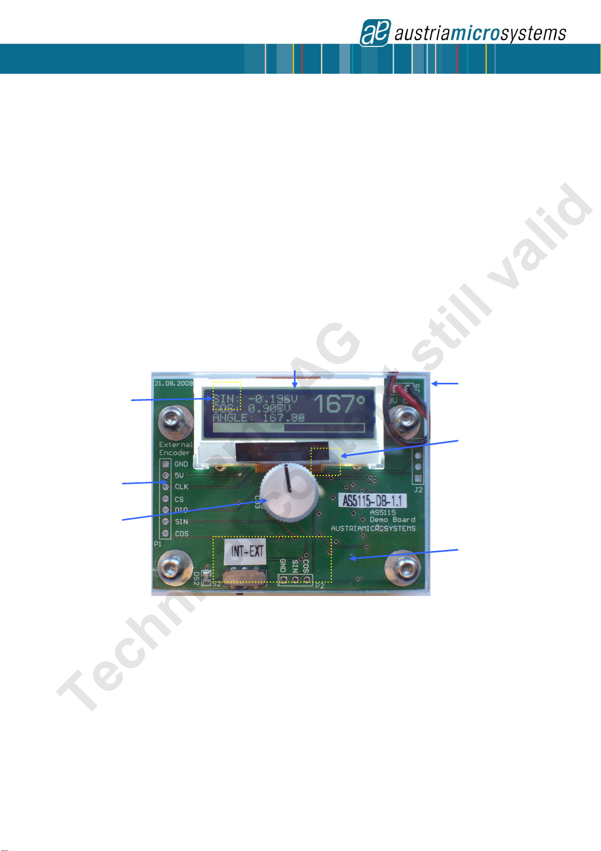
3.1 Hardware Indicator
3.1.1 Graphic LCD di play
The LCD isplay shows the real-time absolute angle position of the magnet as a igital wor (0…360), as well as the
current sine an cosine value of the output voltage.
Turning the knob clockwise will increase the angle value until 359, then 0.
Figure 2: LCD di play in tandalone mode (9V battery or USB powered without GUI)
3.1.2 EXT LED
The EXT LED in icates whether the internal (on boar ) AS5115 or an external evice is use an which values are
shown on the isplay. By switching S2 to the left si e the LED is turne on an one can use an external AS5115 by
connecting it at P1.
The hea er P1 is pin compatible with the AS5115-AB.
4AS5000 Programmer GUI oftware
4.1 In talling the GUI on the PC
The preliminary software is evelope for a Microsoft Win ows XP operating system with Service Pack 2. In a ition
the otnet (.NET) framework version 2.0 or more must be installe on the PC. This package can be ownloa e free of
charge from the Microsoft webpage:
http://www.microsoft.com/ ownloa s/ etails.aspx?FamilyID=0856eacb-4362-4b0 -8e -aab15c5e04f5& isplaylang=en
Following Proce ure is recommen e before starting the GUI:
1. check on your PC if Service Pack 2 is installe
2. install the mentione .NET package to your computer
3. execute setup.exe
4. Finally start the GUI using the shortcut in the start menu or esktop.
4.2 The Home tab
Figure 3 shows the main win ow of the GUI. On the top left corner, boar information as firmware (FW) version an
emoboar name eclaration can be foun .
By efault the GUI is in the auto etection mo e. Any connecte austriamicrosystems emoboar an programming tool will
be automatically etecte an isplaye in the right top corner. The GUI is ivi e into three main sections HOME, TWI an
OTP.
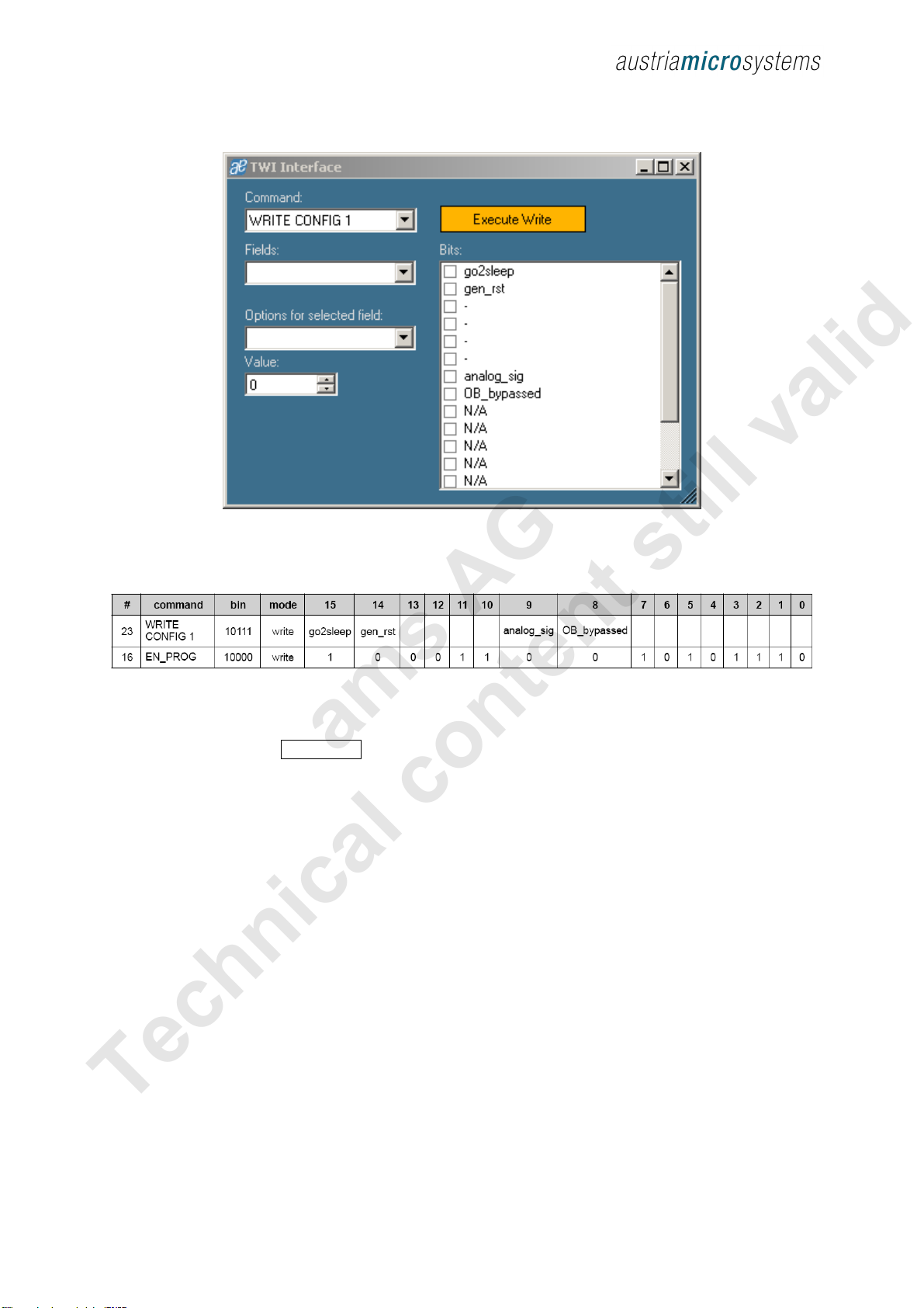
By selecting the TWI (AS5115 bi irectional serial protocol) tab, the information of the angular position appears. See figure 4.
-
Measure SIN an
COS values
- calculate angle value
Magnet angle value in
egree
Raw angle value an
bargraph - same value as
the angle in egree
(1°/step)
ams AG
Technical content still valid

AS5115 Demoboar OPERATIO NAL MANUAL
Revision 1.1, 26.02.2010 Page 3 of 10
www.austriamicrosystems.com
Figure 3: AS5000 GUI detect ed th e AS5115 Demoboard
4.3 The TWI tab
This mo e isplays in realtime the angle value, Multiturn register value, AGC value an the UVW signal status.
Figure 4: TWI tab, allow acce to the AS5115 regi ter from the er ial bu
The Read Interval can be mo ifie from 10 ms (fastest) to 1 s (slowest).
By clicking on Digital Interface, a new win ow opens, an allows the user to write irectly into the AS5115
registers. See chapter 4.4.
Magnet angle value in
egree
Display the Sin an
COS value (graphical
an igital)
Opens the seri
al
comman win ow to
irect access the
internal AS5115
ams AG
Technical content still valid

AS5115 Demoboar OPERATIO NA L MANUAL
Revision 1.1, 26.02.2010 Page 4 of 10
www.austriamicrosystems.com
4.4 Digital Interface ub-window
Figure 5: TWI interf ace u b-window
The Digital interface win ow allows accessing the internal registers of the AS5115:
The parameters on’t nee to be checke manually in the “Bits” win ow on the right, but can be set by the “Fiel s” an
“Options for the selecte bits” values. The correspon ing bits will be checke automatically.
To vali ate the comman , the Execute Write button bust be clicke .
For further information please refer to atasheet.
ams AG
Technical content still valid

AS5115 Demoboar OPERATIO NA L MANUAL
Revision 1.1, 26.02.2010 Page 5 of 10
www.austriamicrosystems.com
4.5 OTP tab
The OTP tab is normally use for the AS5000 programmer, but the OTP bits can be change on the AS5115 emoboar as
well.
Options like gain an Hall bias can be change by selecting the function in “Fields”, then changing the parameter in “Options
for the selected field” or irectly the ecimal value of this parameter in “Value”.
Each time a fiel ’s value has been change , the correspon ing OTP bits will be automatically checke in the right win ow.
The button Write shoul be clicke to write the parameter into the AS5115.
The Rea button rea s back the OTP register, an up ates the “Fiel ” parameter as well as the OTP bits win ow.
Figure 6: OTP t ab
Field Gain: Sets the gain of the internal signal path.
-0: Sensitivity = 1.65
-1: Sensitivity = 1.88
-2: Sensitivity = 2.11
-3: Sensitivity = 2.35
Field Hall Bia : To change the Hall Bias current:
-0 – 63: epen ing on the esire output voltage
Note that the Zap! button is use for the AS5000 Programmer only an has no effect on the AS5115 Demoboar .
ams AG
Technical content still valid

AS5115 Demoboar OPERATIO NA L MANUAL
Revision 1.1, 26.02.2010 Page 6 of 10
www.austriamicrosystems.com
5AS5115 Demoboard Schematic
Figure 7: AS5115 Demoboard chematic
ams AG
Technical content still valid

AS5115 Demoboar OPERATIO NA L MANUAL
Revision 1.1, 26.02.2010 Page 7 of 10
www.austriamicrosystems.com
Index
1General Overview.............................................................................................................................................................. 1
2The AS5115 Demoboar ................................................................................................................................................... 1
3Operating the AS5115 Demoboar ................................................................................................................................... 1
3.1 Har ware In icators.................................................................................................................................................. 2
3.1.1 Graphic LCD isplay ........................................................................................................................................ 2
3.1.2 EXT LED .......................................................................................................................................................... 2
4AS5000 Programmer GUI software................................................................................................................................... 2
4.1 Installing the GUI on the PC ..................................................................................................................................... 2
4.2 The Home tab ........................................................................................................................................................... 2
4.3 The TWI tab .............................................................................................................................................................. 3
4.4 Digital Interface sub-win ow..................................................................................................................................... 4
4.5 OTP tab .................................................................................................................................................................... 5
5AS5115 Demoboar Schematics ...................................................................................................................................... 6
In ex........................................................................................................................................................................................... 7
Revision History ......................................................................................................................................................................... 8
Contact ....................................................................................................................................................................................... 9
Copyright .................................................................................................................................................................................. 10
ams AG
Technical content still valid

AS5115 Demoboar OPERATIO NA L MANUAL
Revision 1.1, 26.02.2010 Page 8 of 10
www.austriamicrosystems.com
Revi ion Hi tory
Revi ion Date De cription
1.0 17.August, 2009 First version
1.1 26. February, 2010 New Demoboar revision v1.2
ams AG
Technical content still valid

AS5115 Demoboar OPERATIO NA L MANUAL
Revision 1.1, 26.02.2010 Page 9 of 10
www.austriamicrosystems.com
Contact
Headquarter
austriamicrosystems AG
A 8141 Schloss Premstätten, Au tria
Phone: +43 3136 500 0
Fax: +43 3136 525 01
in ustry.me ical@austriamicrosystems.com
www.austriamicrosystems.com
Sale Office
austriamicrosystems Germany GmbH
Tegernseer Lan strasse 85
D-81539 München, Germany
Phone: +49 89 69 36 43 0
Fax: +49 89 69 36 43 66
austriamicrosystems Italy S.r.l.
Via A. Volta, 18
I-20094 Corsico (MI), Italy
Phone: +39 02 4586 4364
Fax: +39 02 4585 773
austriamicrosystems France S.A.R.L.
124, Avenue e Paris
F-94300 Vincennes, France
Phone: +33 1 43 74 00 90
Fax: +33 1 43 74 20 98
austriamicrosystems Switzerlan AG
Rietstrasse 4
CH 8640 Rapperswil, Switzerland
Phone: +41 55 220 9008
Fax: +41 55 220 9001
austriamicrosystems UK, Lt .
88, Barkham Ri e,
Finchampstea , Wokingham
Berkshire RG40 4ET, United Kingdom
Phone: +44 118 973 1797
Fax: +44 118 973 5117
austriamicrosystems AG
Klaavuntie 9 G 55
FI 00910 Helsinki, Finland
Phone: +358 9 72688 170
Fax: +358 9 72688 171
austriamicrosystems AG
Bivägen 3B
S 19163 Sollentuna, Sweden
Phone: +46 8 6231 710
austriamicrosystems USA, Inc.
8601 Six Forks Roa
Suite 400
Raleigh, NC 27615, USA
Phone: +1 919 676 5292
Fax: +1 509 696 2713
austriamicrosystems USA, Inc.
4030 Moorpark Ave
Suite 116
San Jose, CA 95117, USA
Phone: +1 408 345 1790
Fax: +1 509 696 2713
austriamicrosystems AG
Suite 811, Tsimshatsui Centre
East Wing, 66 Mo y Roa
Tsim Sha Tsui East, Kowloon, Hong Kong
Phone: +852 2268 6899
Fax: +852 2268 6799
austriamicrosystems AG
AIOS Gotan a Annex 5th Fl., 1-7-11,
Higashi-Gotan a, Shinagawa-ku
Tokyo 141-0022, Japan
Phone: +81 3 5792 4975
Fax: +81 3 5792 4976
austriamicrosystems AG
#805, Dong Kyung Bl g.,
824-19, Yeok Sam Dong,
Kang Nam Gu, Seoul
Korea 135-080
Phone: +82 2 557 8776
Fax: +82 2 569 9823
austriamicrosystems AG
Singapore Representative Office
83 Clemenceau Avenue, #02-01 UE Square
239920, Singapore
Phone: +65 68 30 83 05
Fax: +65 62 34 31 20
ams AG
Technical content still valid

AS5115 Demoboar OPERATIO NA L MANUAL
Revision 1.1, 26.02.2010 Page 10 of 10
www.austriamicrosystems.com
Copyright
Devices sol by austriamicrosystems are covere by the warranty an patent in emnification provisions appearing in its
Term of Sale. austriamicrosystems makes no warranty, express, statutory, implie , or by escription regar ing the
information set forth herein or regar ing the free om of the escribe evices from patent infringement. austriamicrosystems
reserves the right to change specifications an prices at any time an without notice. Therefore, prior to esigning this
pro uct into a system, it is necessary to check with austriamicrosystems for current information. This pro uct is inten e for
use in normal commercial applications.
Copyright © 2009 austriamicrosystems. Tra emarks registere ®. All rights reserve . The material herein may not be
repro uce , a apte , merge , translate , store , or use without the prior written consent of the copyright owner. To the
best of its knowle ge, austriamicrosystems asserts that the information containe in this publication is accurate an correct.
However, austriamicrosystems shall not be liable to recipient or any thir party for any amages, inclu ing but not limite to
personal injury, property amage, loss of profits, loss of use, interruption of business or in irect, special, inci ental or
consequential amages, of any kin , in connection with or arising out of the furnishing, performance or use of the technical
ata herein. No obligation or liability to recipient or any thir party shall arise or flow out of austriamicrosystems ren ering of
technical or other services.
ams AG
Technical content still valid
Table of contents
Other ams AG Motherboard manuals