OUT R OUT L
(MONO)
TS-UNBAL
TRS-BAL.
MIDI IN/
F.SW-A
EXP/
F.SW-B CTRL
IN/OUT
PHONES
A
1 2
EXT.
F.SW
B
1 2
EXT.
F.SW
EXT.F
CHECK
U2
ULTIMA
BRAIN FRAME
PANGAEA
CLIP/
TAP
CONFIRM
ESC/
EDIT
United Bricks of Russia
IN R
IN L
(MONO) AUX IN
DC 12V
USB
1. OUT R: TRS balanced one output connector of the device’s RIGHT channel.
With a TS cable’s connector, it can be used as an unbalanced one output.
The output level can be adjusted from +4 dBV to zero so it can be used with
both line and microphone inputs.
2. MIDI IN/F. SW-A: TRS stereo mini jack 3.5 mm multi-function connector
is for connecting the MIDI OUT from an external device or two-button
footswitch.
3. PHONES: Headphones stereo mini jack 3.5 mm. It receives sound from the
OUT R (1) and OUT L (MONO) (5) output channels + a sound applied to the
AUX IN (22) input.
4. EXP/F. SW-B: TRS stereo mini jack 3.5 mm multi-function connector is for
connecting an expression pedal or two-button footswitch.
5. OUT L (MONO): TRS balanced one output connector of the device’s LEFT
channel. With a TS cable’s connector, it can be used as an unbalanced one
output. The output level can be adjusted from +4 dBV to zero so it can be
used with both line and microphone inputs.
6. CTRL IN/OUT: TRS mini stereo jack 3.5 mm external control connector
(input/output) for connecting AMT Bricks preamps.
7. ENCODER: Main control element used for menu navigation and setting
parameters.
8. ESC/EDIT: Button for entering the preset editing mode and exiting (also
from other device’s modes).
9. OLED: Main display.
10. FOOTSWITCH BUTTON: Could works in two different modes
simultaneously — short or long-pressing. It can perform various functions
depending on the selected functionality of the U2 device and its settings. For
example, it can turn on effects, switch presets, or going in TUNER mode.
11/12/13/14 — EXT. F. SW A1/A2/B1/B2 LEDs: Indicators the status of the
contacts of external footswitches connected to MIDI IN/F. SW-A (2) and
EXP/F. SW-B (4) connectors. LEDs «A» are responsible for the TIP contacts,
LEDs «B» — for the SLEEVE contacts.
15. CLIP/TAP: LED indicates different states depending on the device’s
functionality. For example, the DELAY effect makes it flashes according to
the time set for delay or modulation. Also, this LED indicates the excess of
the allowed input signal level.
16. PROTECTIVE ARC.
17. EXT. F: LED is used when the U2 is working as a part of the AMT
Pedalboard system.
18. CHECK: LED indicating the effect’s activation. Depending on the device’s
functionality, this LED may also display other device states.
19. USB: Mini USB port for connecting the device to your computer by a
cable. It allows you to update the device Firmware, download IR files, copy
the device presets to/from the computer.
20. DC 12V: Connector for the power supply (voltage DC 12V, min. 300mA,
central contact — negative)
21. IN R: TS unbalanced audio input of the RIGHT device’s channel. If you’re
connecting to the U-2 device with only one mono audio signal, please use
the IN L (MONO) (23) input instead of this IN R (21).
22. AUX IN: TRS mini stereo jack 3.5 mm input for connecting an additional
audio signal (the backing track for the practice or as a personal monitoring
system). The signal from the AUX IN input goes only to the PHONES output
and does not go to the main outputs OUT L, OUT R.
23. IN L (MONO): TS unbalanced audio input of the LEFT device’s channel. If
you’re connecting to the U-2 device with only one mono audio signal, please
use this one input instead of the IN R (21).
24. PETALS: Technological elements with holes for mounting the device on
your pedalboard.
25. BRICKS CONNECTOR: Interface connector for the device operation as
part of the AMT Bricks Pedalboard.
1 3 5 6
2 4
7
8
9
10
12
11
13
14
18
17
16
15
19
23 22 21 20
24
25
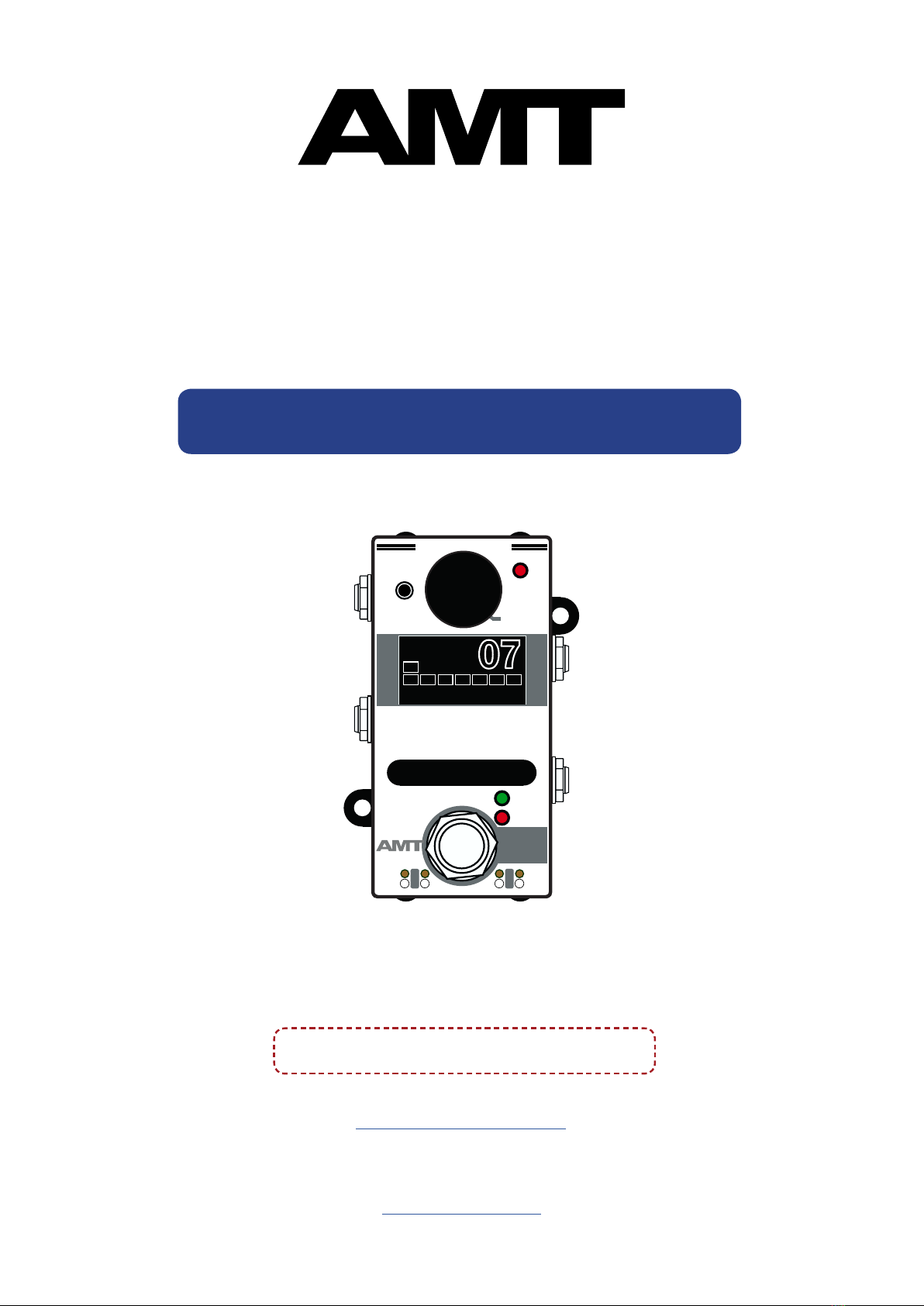
Device appearance
Owner’s Manual for AMT Pangaea Ultima U-2
Firmware «07 - BassMix FX» 4