KV2 Audio 500 Series User manual

User Guide
KV2's 500 SERIES
· TCL · QD8 · MPA

KV2's 500 SERIES · Content
Content
KV2's 500 SERIES · Important Safety Instructions · Installation 4
TCL 5 - 9
Overview 5 - 7
Block diagram 8
Specications 9
QD8 10 - 13
Overview 10 - 11
Block diagram 12
Specications 13
MPA 14 - 19
Overview 14 - 17
Block diagram 18
Specications 19
Warranty · Service 20
Notes 21 - 22
KV2's 500 SERIES · Content

4
KV2's 500 SERIES · Safety Instruction
Important Safety Instructions
Before using your TCL, QD8, MPA be sure to carefully read the applicable items
of these operating instructions and the safety suggestions.
1. Read all product instructions.
2. Keep printed instructions, do not throw away.
3. Respect and review all warnings.
4. Follow all instructions.
5. Clean only with dry cloth.
6. Install in accordance with KV2 Audio's recommended installation instructions.
7. Only use accessories specied by KV2 Audio.
8. An experienced user shall always supervise this professional audio equipment.
Installation Safety Instructions
To install the KV2’s 500 Series modules into a 500 series chassis:
1. Turn o the power to the 500 series chassis.
2. Unpack the module and ensure the rear connector is free of debris.
3. Align and slide the module into the 500 series chassis, ensuring the connectors
on the back properly seat with the connectors in the chassis.
4. Install the included screws to secure the module to the chassis. Both metric
and standard screws are included. Use the correct screw type for your chassis.
5. Power on the chassis.
6. Enjoy!
WARNING! Do not hot swap 500 series modules! Doing so can potentially cause
damage to the 500 series module or chassis. Always power down the chassis when
installing or removing 500 series modules.
KV2's 500 SERIES · Important Safety Instructions · Installation

TCL · Overview
Introduction
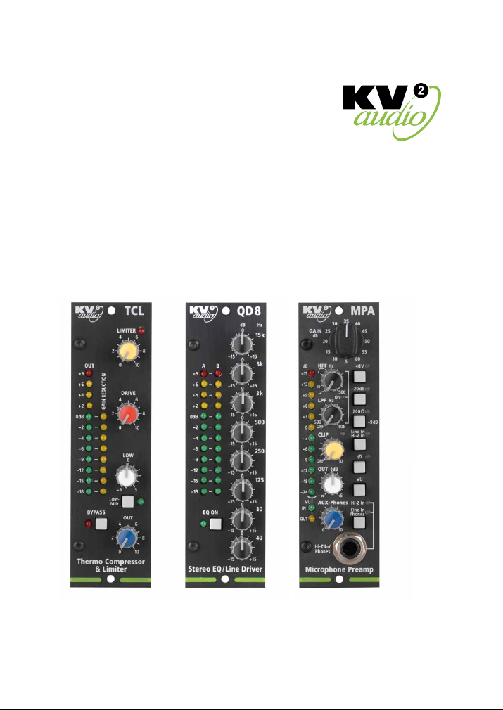
The TCL is a unique analog thermo audio compressor featuring a superior natural
RMS detector and dynamic voice bass enhancement control. In another KV2 rst
its patented design oers an exceptionally musical and natural compression that is
a component part of its real-time input, rather than a typical side fed gain reduction
circuit attempting to either
follow or anticipate compression
demands. Its additional Bass
balance control circuit allows
the user to smooth out
and minimise any proximity
eects from a changing
microphone position, giving
the perfect voice color to every
performance, from beginning
to end. Featuring source intelligent
attack and release times, whatever
the dynamic content, with just
a few simple steps the results
from the 500 Series TCL are truly
exceptional.
Application
• The TCL is the ultimate
compression tool for various
studio and live applications
with instruments and voice.
• The TCL perfectly suits Musical
theatre - giving consistency,
richness and depth to head
worn microphones.
• The TCL is ideal for corporate
TCL - 500 SERIES
Superior RMS - Audio Thermo-Compressor with Limiter
TCL - part number KVV 987 478
5
TCL · Overview

6
TCL · Overview
presentations - giving a full, warm, full voice timbre and allowing tone
matching for lecturn and lavalier microphones.
• The TCL can be used live on many musical instruments, both classical
and contemporary.
Controls
1) LIMITER
Serves to set the maximum input level. Any subsequent levels above the set level
are hard limited.
This ensures that any connected devices further down the signal chain are not
aected by an overloaded input The limiter’s active state is indicated by the limiter
LED.
2) DRIVE
This control sets the drive level for the input of the compressor’s gain reduction
circuit.
3) LOW
Serves as a low frequency enhancement circuit by rerouting some signal from
the second in line thermo-compressor through a low pass lter, providing a full
and warm bass enriched sound, even under compression.
Select the required bass enhancement by sweeping the pot in a clockwise
direction, where the center position presents a at frequency response,
with additional bass enhancement available beyond that point.
The combined output of its signal path after gain reduction and the bass
enhancement circuit blend, monitor and balance themselves perfectly
in real-time to maintain the all important voice color within a 20dB range.
Controls
4) LOW-MID Switch
This switch allows two alternate settings of the low pass lter frequency
in the thermo-compressor LF enhancement circuit. This can be set to the operators
preference depending on personal taste, microphone type and individual voice
characteristics. (Male / female etc)
TCL · Overview

7
TCL · Overview
5) OUT
Adjusts the output level.
6) METERS
Output level meter – a 12 segment, 3 color peak reading meter serves to monitor
the output signal level. If the red PEAK light ashes, the signal level is too high
and should be reduced to prevent possible overload distortion.
Gain reduction level meter – an 8 segment level meter displaying the amount
of gain reduction performed by the compressor.
7) BYPASS
Serves as a TCL module bypass.
Please Note - In bypass mode all meters and LED indicators will still show the lastest
operation mode, but the audio path is unaected by any of the settings.
TCL · Overview

TCL · Block diagram
Block diagram
8
TCL · Block diagram

TCL · Specications
Specications
System Acoustic Perfomance
-3dB Response 15Hz to 100kHz
Total Harmonic Distortion <0.002%
Signal Input
Input Channels 1
Input Impedance 20kΩ
Max. Input voltage +26dBu
Features Limiter, Compressor, Bass enhancer
Signal Output
Signal Output Channels 1
Max. Output Voltage 18dBu (600Ω) RMS
Output Impedance 600Ω
Features
Limiter Adjustable
Drive Adjustable
Bass enhancement Adjustable
Low-Mid Selects the bass enhancement LPF frequency
Output Adjustable
Indicators 12 segment VU meter, 8 segment gain reduction
Bypass Yes
Power Requirements
Power Consumption 120mA
Operating Voltage ±16V
Physical Dimensions
API Series 500 format One slot
9
TCL · Specications

QD8 · Overview
Introduction
A revolutionary George Krampera 8-band Equaliser specically designed
to highlight a desired band without adversely aecting the overall sonic landscape.
Whilst not intended for tuning out room modes, the frequency bands and lter
types have been precisely chosen after extensive research, to perfectly align
with the science of human hearing and our perception of achieving the ultimate
spectral balance. In a Live scenario,
faced with a number of dierent
sources, program types,
or performance genres
at a festival or concert,
the equaliser is very musical,
intuitive and an exceptionally
quick way to shape any mixed
content to the sound you want
to hear. In the studio, it can be
either the simple enhancement
of an instrument / vocal track,
or the nal mastering polish
to take an ordinary mix
and make it something very
special.
NOTE
As the QD8 is a stereo
(two channel unit) it will require
a series 500 Rack that facilitates
dual channel input and outputs.
It is also recommended to insert
the QD8 as the last unit
in the series 500 chain, directly
before the ampliers/speakers.
QD8 - 500 SERIES
Stereo 8-band Master Equaliser with Line Driver
1
3
2
QD8 - part number KVV 987 477
10
QD8 · Overview

QD8 · Overview
Application
• For use in Recording Studios as a master equaliser, single instrument, or group
equaliser.
• Front of House PA system master equaliser, the unit is also equipped with line
drivers designed to maintain audio signal integrity over long cable lengths
(up to 200 m).
• Single stereo zone or dual mono system equaliser, to sonically match dierent
ll speakers and zones with the main FOH PA when used in multiples.
• To reduce the harshness in some digital recordings, particularly around
the 6kHz region.
Controls
1) 8-Band Equaliser
The Equalizer boosts or cuts frequencies at 40, 80, 120, 250, 500, 3000, 6000
and 15000 Hz by +/-15dB.
2) Output level meter
A 12 segment, 3 color peak reading meter serves to monitor the output signal level.
The signal should average around '0dB'. If the red PEAK light ashes, the signal level
is too high and should be reduced to prevent possible overload distortion.
Controls
3) EQ ON switch
8-band Equaliser EQ enable switch. When depressed, the EQ is bypassed.
NOTE
It is recommended to insert the QD8 as the last unit in the series 500 chain, directly
before the ampliers/speakers.
11
QD8 · Overview

QD8 · Block diagram
Block diagram
12
QD8 · Block diagram

QD8 · Specications
Specications
System Acoustic Perfomance
-3dB Response 10Hz to 100kHz
Total Harmonic Distortion <0.001%
Signal Input
Input Channels 2x
Input Impedance 20 kΩ
Max. Input voltage +26dBu
Signal Output
Signal Output Channels 2x
Max. Output Voltage 18dBu (600Ω) RMS
Max. Output Current 300mA
Output Impedance 50Ω
Features
Equalization 8-band EQ
Output Line driver
Power Requirements
Power Consumption 160mA
Operating Voltage ±16V
Physical Dimensions
API Series 500 format One slot (dual channel series 500 rack required)
13
QD8 · Specications

MPA · Overview
Introduction
The MPA is a Very High Denition microphone and musical instrument preamplier
with Class-A circuitry and a high quality transformer balanced output. A stepped
Input gain selector is provided for easy and precise repeatability of settings.
The preamplier features adjustable high and low pass lters, with an adjustable
limiter to control clip level and a transformer isolated high impedance line input.
It also has a further auxiliary transformer balanced isolated output meaning
a number of these units can be used together to make a multi-channel stage
preamp, for splitting FOH
and monitoring outputs,
or for broadcast and recording
duties -delivering them all through
line drivers in pristine audio quality.
Phase reverse and an in-built
headphone amplier, which
doubles up as a third output,
completes the feature rich unit.
With the exceptional quality
of all KV2’s analog outboard
electronics, the MPA can replace
a preamplier, Di-box/Splitter,
line driver and headphone
amplier all in one box.
Application
• A Very High Denition studio
recording preamplier with low
noise and increased dynamic
range.
• A stage preamplier and splitter
with Line driver capability
and Class-A circuitry.
MPA - 500 SERIES
Microphone preamplier
MPA - part number KVV 987 482
14
MPA · Overview

15
MPA · Overview
• An esoteric Musical Instrument preamplier with lters, Hi-Z input and Class-A
circuitry.
Controls
1) GAIN
Adjusts the MPA’s input gain from +5dB to +60dB with 5dB steps. In conjunction
with the 200 Ω setting a total gain of 74dB is available.
2) 48V
Supplies +48 V to pins 2 and 3 of the main input XLR for microphones, or devices
which require phantom power.
3) -20dB
Applies the -20dB PAD for the main XLR input.
Controls
4) 200 Ω
Switches the input transformer to accept a 200 Ω load impedance. The input
sensitivity increases by +9dB. This serves as an input for equipment requiring
a 200 Ω loading and also as a galvanic isolator, for dynamic microphones, ribbon
microphones or line level outputs. This setting helps to increase the signal to noise
ratio of low level output sources (e.g. ribbon microphones).
5) Line In / Hi-Z In
This switch selects between the Main Mic input (XLR) and AUX input (XLR or front
panel Jack). The AUX input sensitivity is reduced by -15dB. The front panel Jack
input sensitivity is reduced by -10dB.
6)
Applies output signal phase reverse. Both main XLR output and AUX output are
reversed at the same time.
7, 16) VU
Selects the signal meter display between input and output levels. The ‘IN’ and ‘OUT’
LEDs as shown at 16) indicate the current state of metering.
MPA · Overview

MPA · Overview
8) Hi-Z In / Phones
Selects the front panel Jack function between the high impedance input and phones
output.
9) Front panel Jack 6,3mm
Serves as a high impedance input or Phones output.
Controls
10) HPF, FIX/TUNE (in conjunction with control 11)
The controls 10) and 11) are designed to be operated together as an overall
HPF/LPF circuit. To realise any settings from control no 10) you must rst turn
on the overall HPF/LPF section using control no 11). Turning this control from
the o click position fully clockwise to the 50kHz setting will give you an open,
extended high frequency setting without an audible lter. This gives an option
to use just the HPF feature on its own by adjusting control no 10) leaving no 11)
fully clockwise.
The rst position on the control 10) is fully anti clockwise. This is not the o position
but in fact a special ‘FIXED VOCAL PRESET’designed by George Krampera.
This preset has been optimised to maintain a rich and full vocal quality, retaining
and shaping the most important bass frequencies, whilst reducing any problematic
low frequency content or typical rumble.
The next part of the control is a tuneable high pass lter (HPF) selected by turning
the control clockwise past the click. Select the required cut o frequency by sweeping
from 10Hz to the maximum 500 Hz (when fully clockwise) The lters are adaptive,
which means they change their characteristics depending on what frequency is
selected. The lower the frequency that is applied, the steeper the lter is tuned.
11) LPF
A tuneable low pass lter (LPF). This can be applied to clean up sounds from any
unwanted high-frequency content. Once switched on, select the required cut o
frequency by sweeping anticlockwise from the maximum 50 kHz down to 500 Hz.
The LPF drops by 12dB per octave above the cut o frequency.
NOTE-To use this LPF in isolation without any additional HPF adjustments set the
control above no 10) to the minimum tuneable setting of 10Hz (Not the fully anti
clockwise ‘Fixed vocal preset’ position).
16
MPA · Overview

MPA · Overview
12) CLIP
The Clip limiter control sets the maximum output level, with all levels above this
point limited. After switching on the clip circuit with a clockwise turn, the red LED
to the right will indicate when the circuit is actively limiting. This ensures any further
devices in the signal chain are not aected by undesired clipping or distortion.
13) OUT
Adjusts the output level from -∞ to +5dB.
14) AUX-Phones
Adjusts the AUX and Phones output levels.
15) Input/Output level meter
A 12 segment, 3 color peak reading meter serves to monitor input or output signal
levels depending on the position of the VU switch no 7). The signal should average
around '0dB'. If the red PEAK light ashes, the signal level is too high and should be
reduced using the GAIN control to prevent possible overload distortion.
17
MPA · Overview

MPA · Block diagram
Block diagram
18
MPA · Block diagram

MPA · Specications
Specications
System Acoustic Perfomance
-3dB Response 10Hz to 100kHz
Total Harmonic Distortion <0.002%
Signal Input
Input Channels 3x
Input Impedance 2kΩ / 200Ω Mic (+9dB), 1MΩ Hi-Z In
Max. Input voltage +26dBu
Mic input Phantom power, -20dB, Gain, Phase, LPF, HPF
Line input Hi-Z, Input transformer
Signal Output
Signal Output Channels 3 (Main, Aux, Phones)
Max. Output Voltage 19dBu (50Ω) RMS
Recommended loading ≥50Ω balanced, ≥600Ω AUX unbal.,
≥10Ω phones
Features
Input Level Control +5 to +60dB, 5dB step, total gain 74dB
High Pass Filter Vocal preset / 10Hz to 500Hz
Low Pass Filter 500Hz to 50kHz
Clip Adjustable
Indicators LED, 12 segment VU meter
Phantom power 48V
Power Requirements
Power Consumption 250mA
Operating Voltage ±16V
Physical Dimensions
API Series 500 format One slot
19
MPA · Specications

KV2's 500 SERIES · Warranty · Service
Warranty
Your 500 SERIES is covered against defects in material and workmanship.
Refer to your supplier for more details.
Service
In the unlikely event that your 500 SERIES develops a problem, it must be returned
to an authorised distributor, service centre or shipped directly to our factory.
Because of the complexity of the design and the risk of electrical shock, all repairs
must be attempted only by qualied technical personnel.
If the unit needs to be shipped back to the factory, it must be sent in its original
carton. If improperly packed, the unit may be damaged.
To obtain service, contact your nearest KV2 Audio Service Centre, Distributor
or Dealer.
20
KV2's 500 SERIES · Warranty · Service

21
KV2's 500 SERIES · Notes
21
KV2's 500 SERIES · Notes
This manual suits for next models
6
Table of contents
Other KV2 Audio Recording Equipment manuals