Anaheim Automation DPN10601 User manual

September 2012L010155 1
DPN10601
Programmable Driver Pack
User’s Guide
4985 E. Landon Drive Anaheim, CA 92807
e-mail: [email protected]
(714) 992-6990 fax: (714) 992-0471
website: www.anaheimautomation.com
ANAHEIM AUTOMATION
July 2018

September 2012L010155 2
Table of Contents
Section 1: Introduction.................................................................................................................................3
Description.....................................................................................................................................................3
Electrical Specications..............................................................................................................................4
Ordering Information.......................................................................................................................................4
Dimensions/Switch Locations.....................................................................................................................5
Wiring Diagrams.........................................................................................................................................5
Terminal Descriptions - Power.........................................................................................................................6
Terminal Descriptions - Driver......................................................................................................................6
Motor Ground..............................................................................................................................................7
Terminal Descriptions - Controller....................................................................................................................7
Connector Descriptions - Controller.................................................................................................................7
Slide Switch Descriptions - Controller.............................................................................................................7
Section 2: Driver Functions..........................................................................................................................8
Motor Selection...........................................................................................................................................8
Step Motor Current Setting Guide......................................................................................................................8
Microstep Selection - Driver SW1 Settings..................................................................................................9
Setting the Output Current..........................................................................................................................9
Reducing Output Current...........................................................................................................................10
Determine Output Current...........................................................................................................................10
Step Motor Congurations...........................................................................................................................10
Connecting the Step Motor..........................................................................................................................12
Short-Circuit, Mis-Wire, and Over-Current Conditions....................................................................................12
Over-Temperature and Over-Voltage Conditions............................................................................................12
Section 3: Controller Functions..................................................................................................................13
Methods of Communication.......................................................................................................................13
Baud Rate................................................................................................................................................13
RS232 Protocol - Controller SW1 in RS232 Position........................................................................................13
RS485 Protocol - Controller SW1 in RS485 Position....................................................................................13
Axis Selection...........................................................................................................................................14
Controller Status LED..................................................................................................................................14
Technical Support.........................................................................................................................................14
Section 4: SMC60WIN Software.................................................................................................................19
File Menu..................................................................................................................................................20
Setup Menu..............................................................................................................................................20
Setup - Axis Menu.....................................................................................................................................20
Program Menu............................................................................................................................................21
Program - Autostart Program Menu............................................................................................................21
Edit Menu..................................................................................................................................................22
Help Menu................................................................................................................................................22
“The Unit is Connected” / “The Unit is NOT Connected”..................................................................................23
Toolbar......................................................................................................................................................23
Tab Sheets................................................................................................................................................28
Add/Change/Insert Commands................................................................................................................28
Calculator..................................................................................................................................................33
Section 5: Direct Talk Mode....................................................................................................................34
Section 6: Troubleshooting.....................................................................................................................44
Errors Codes.............................................................................................................................................45
Section 7: Sample Programs.....................................................................................................................46
Appendix 1: ASCII Table for Direct Mode..................................................................................................51
Appendix 1: ASCII Table for Direct Mode...................................................................................................51
Copyright .................................................................................................................................................52
July 2018

September 2012L010155 3
Introduction
The DPN10601 is a single-axis 10A bipolar microstep driver/controller containing 2 Kbytes of
nonvolatile stored programming space, quadrature encoder feedback, and a 300W transformer,
all enclosed in a package. It provides exible, independent control of bipolar stepper motors with
a current range from 1.5 to 10.0 amps/phase with microstepping resolutions from 200 steps per
revolution to 12,800 steps per revolution from a computer, or any machine controller with a se-
rial port. It is also capable of standalone operation, making it an embedded machine controller.
The easy to use Windows software, SMC60WIN, can be used to directly control motion and to
program the DPN10601. The DPN10601 also has the ability for real time functions.
The DPN10601 has 40 commands, which are easy-to-remember for direct movement of the step-
per motor and communicates via either an RS232 or RS485 bidirectional serial data bus. Up to
99 DPN10601’s can be networked from one communications port on your PC or PLC, utilizing
the RS485 communications protocol. Special functions of the controller include 8 programmable
open collector outputs and 6 TTL, CMOS and 24V compatible inputs, a quadrature encoder input
with the ability to autocorrect, and analog input to control either maximum speed or absolute posi-
tion, registration mark indexing during a slew command, an output that will trigger during an index
command at an absolute position, and a thumbwheel input for indexing a motor. The DPN10601
can be powered from 90-265 VAC, 50/60Hz.
Section 1:
Description
The driver in the DPN10601 (MBC10641) is a microstep motor driver that can drive motors rated from
1.5 to 10.0 amps/phase. It can handle 4, 6 and 8-lead motors in a bipolar fashion. The DPN10601’s
driver features motor current ON/OFF capabilities and a Reduced Current Enable to automatically
reduces motor current to 70% of the set value after the last step is made (20msec delay). With the
DPN10601, various step resolutions can be implemented by the onboard dip switch. These division
range from 200 steps per revolution to 12,800 steps per revolution. Protection devices have been
added to this driver for short circuit, open circuit, over circuit, under voltage and over temperature
conditions. The driver has built-in features to indicate power on (Green LED), Clocks being received
(Yellow LED) and fault conditions (Red LED).
The controller in the DPN10601 (PCL601) provides independent programming of acceleration/de-
celeration, base speed (start up speed), max speed (running speed), jog speed, and the number of
steps to be taken in both relative and absolute positioning modes. On absolute positioning moves, the
DPN10601 automatically determines the proper direction to go and the number of steps to take. The
relative positioning will move a number of steps in the direction that the user denes. The DPN10601
also has specic functions such as encoder feedback, autocorrection, index-on-the-y and output-on-
the-y. An analog input can be used to set either the maximum speed or go to an absolute position
based between the upper and lower programmable limits. A seven decade thumbwheel switch can
be read for relative indexing. The DPN10601 also has a high level programming command set that
includes: branching, looping, conditional statements, time delays, text strings, and I/O which the user
can use in the programming mode to fully control all machine functionality. A home input, a set of
bidirectional hard and soft limit switch inputs and bidirectional jog inputs are provided for each axis.
These features are generally required in most machine control designs. 6 testable TTL, CMOS and
24V compatible inputs and 8 programmable open-collector outputs are provided per axis. The I/O
may be used for monitoring and controlling machine operation and/or interaxis coordination. The
I/O are accessible independent of the busy state of the axis controls. The DPN10601 has a built-in
programmable reset circuit. Reset is automatic on power-up, or by pressing the external reset button.
July 2018

September 2012L010155 4
Electrical Specications
Power Requirements:
90-265 VAC 50/60Hz
Operating Temperature:
0 to 60° C
Pulse Output Range:
1 to 50,000 Hz
10ɥS negative going pulse width
Inputs (TTL-CMOS):
Logic “0”: 0 to 0.8VDC
Logic “1”: 3.5 to 24VDC
Analog Input 1: 0 to 5VDC
Excitation Mode Select:
Pulled up to +5VDC through 10K
Logic “1” (open) - Half Step
Logic “0” - 2 Phase Full Step
Output Current Rating:
10.0 A/phase maximum running
7.0A/phase maximum standstill
Baud Rate:
38400 Baud, Fixed
Data Format:
Half-Duplex, 1 start bit, 8 data bits,
no parity, 1 stop bit
Outputs (8 programmable):
Open Drain Type
40V, 100mA
+5VDC Output, 50mA
Output 1 active low time for output
on the y:
50uS
Note: For inductive loads, customers must
connect a clamping diode to protect from
yback voltage spikes.
Ordering Information
The table below lists a variety of products available from Anaheim Automation, Inc. These prod-
ucts include those covered by this manual, analog with supporting cables and devices. We are
continually adding new products to our line, so please consult Anaheim Automation, Inc. or its
representatives for information on the latest releases.
Part Number Description
DPN10601 Controller/Drive Pack - Features a 10 amp bipolar drive and power supply.
DPD75601 Controller/Drive Pack - Features a 7 amp unipolar drive and power supply.
485SD9TB RS232 to RS485 converter.
TWS7 Seven position thumbwheel switch compatible with any SMC60 series controller.
AA9MFC-6 6 foot straight through serial cable with one DB9 male and one DB9 female connector.
A CD, provided when you purchase the unit, contains this user’s manual, along with the SMC-
60WIN software and DPN10601 program examples. The software allows you to write and change
programs that are to be stored in the DPN10601 for autostart use, and also upload the program
that is store in the DPN10601 itself for editing and viewing. The software also allows you to save
the programs onto your computer hard drive, and easily retrieve them when needed.
July 2018
September 2012L010155 5
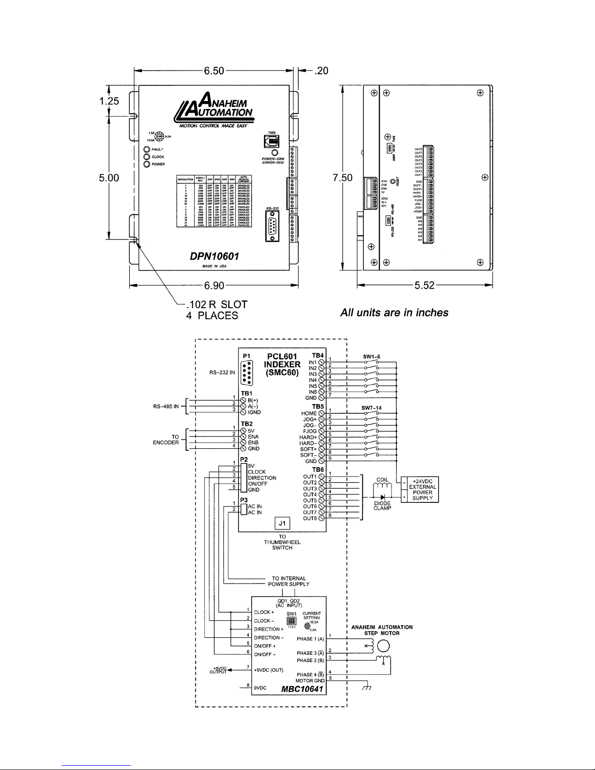
Dimensions/Switch Locations
Wiring Diagrams
July 2018

September 2012L010155 6
Position Description - Motor Connection
1 Step Clock Input Anode (+): Internally Connected to Controllers +5VDC.
2 Step Clock Input Cathode (-): Internally Connected to controllers clock output.
3 Direction Anode (+): Internally Connected to controllers +5VDC.
4 Direction Cathode (-): Internally Connected to controllers direction output.
5 ON/OFF Anode (+): Internally Connected to controllers +5VDC.
6 ON/OFF Cathode (-): Internally Connected to controllers on/off output.
7 +5VDC: This non-isolated output can be used to supply up to 50mA of current.
8 .0VDC: +5VDC Return.
Terminal Descriptions - Power
The DPN10601 is powered by an AC line voltages ranging from 90-265VAC. The following gure
shows the various line voltages and the wiring for the power connection terminal block.
Terminal Descriptions - Driver
Position Description - Motor Connection
1 Phase A: Phase 1 of the Step Motor
2Phase Ā: Phase 3 of the Step Motor
3 Phase B: Phase 2 of the Step Motor
4 Phase B: Phase 4 of the Step Motor
5 Motor Ground
July 2018

September 2012L010155 7
Connector Descriptions - Controller
Slide Switch Descriptions - Controller
Position Description - Encoder
1 A(-)
2 B(+)
3IGND - This is an isolated ground for
RS485 only
Position Description - Limit Switch Inputs
1 +5VDC supply for encoder
2 A channel for encoder
3 B channel for encoder
4 Ground return for encoder
Position Description - Limit Switch Inputs
1 Home Limit
2 Jog +
3 Jog -
4 Fast Jog
5 Hard Limit +
6 Hard Limit -
7 Soft Limit +
8 Soft Limit -
9 Ground
Position Description - Motor Connection
1 Input 1 - Analog Input
2Input 2 - Index on the y input
3 Input 3
4 Input 4
5 Input 5 - SW2 in position IN5/6
6 Input 6 - SW2 in position IN5/6
7 Ground
Position Description - Outputs
1Output 1 - Output on the y output
2 Output 2
3 Output 3
4 Output 4
5 Output 5
6 Output 6
7 Output 7
8Output 8 - Encoder Retries Error Output
Switch Description
P1 This connector is for the RS-232 communication and is labeled RS-232.
J1 This connector is for the thumbwheel module and is labeled TWS.
Switch Description
SW1 This switch is used to select either RS232 or RS485.
SW2 This switch is used to select either the thumbwheel or inputs 5 and 6.
Terminal Descriptions - Controller
Motor Ground
Meant to be used in conjunction with the motor cable ground wire. Make sure the connection is
only on one end of the motor cable ground wire. If no motor shield is available, and if the motor
has no ground wire, the motor ground pin can be left with no connection.
July 2018

September 2012L010155 8
Motor Selection
The DPN10601 incorporates a Bipolar Microstep Driver that is compatible with both Bipolar and
Unipolar Motor Congurations, (i.e. 8 and 4 lead motors, and 6 lead center tapped motors).
Step motors with low current ratings and high inductance will perform better at low speeds, pro-
viding higher low-end torque. Motors with high current ratings and low inductance will perform
better at higher speeds, providing more high-end torque.
Since the DPN10601 is a constant current source, it is not necessary to use a motor that is rated
at the same voltage as the supply voltage. What is important is that the driver is set to the ap-
propriate current level based on the motor being used. Refer to the following chart for setting
the current potentiometer based on the current code in the part number of the motor. Examples
of the motor part numbers are shown below. Anaheim Automation offers a comprehensive line
of step motors in 14, 17, 23, 34 and 42 frame sizes. Contact the factory to verify motor compat-
ibility with the DPN10601.
Section 2: Driver Functions
Motor Example Motor Current
Number Code
Unipolar
Rating
Series Peak
Rating
Parallel
Peak
Rating
Series
Current
Setting
Parallel
Current
Setting
23102S 02 1.0A 1.0A 2.0A ---- 5%
23L303D-LW8 03 1.5A 1.5A 3.0A 0% 20%
34N104S-LW8 04 2.0A 2.0A 4.0A 5% 30%
23L4005D-LW8 05 2.5A 2.5A 5.0A 10% 40%
34A106B 06 3.0A 3.0A 6.0A 20% 50%
34N207S-LW8 07 3.5A 3.5A 7.0A 25% 60%
34K108S-LW8 08 4.0A 4.0A 8.0A 30% 70%
42N209S-CB 09 4.5A 4.5A 9.0A 35% 85%
23L310S-LW8 10 5.0A 5.0A 10.0A 40% 100%
34D311D 11 5.5A 5.5A 11.0A 45% 100%
42K112S-CB 12 6.0A 6.0A 12.0A 50% 100%
34D213S 13 6.5A 6.5A 13.0A 55% 100%
34N314S-LW8 14 7.0A 7.0A 14.0A 60% 100%
42N115D-CB 15 7.5A 7.5A 15.0A 65% ----
34K416S-LW8 16 8.0A 8.0A 16.0A 70% ----
42D119D 19 9.5A 9.5A 19.0A 90% ----
42N322S-CB 22 11.0A 11.0A 22.0A 100% ----
42D225S 25 12.5A 12.5A 25.0A 100% ----
Step Motor Current Setting Guide
Anaheim Automation offers motor cable, making hook-ups quick and easy!
Contact the factory or visit our website for more motor and cable offerings.
Table 5: Table selection for Anaheim Automation motor Current settings.
July 2018

September 2012L010155 9
Microstep Selection - Driver SW1 Settings
Switches 2, 3 and 4, of the DIP switch select the number of microsteps per step. Table 6 shows
the standard resolution values along with the associated positions for the select switches. The
standard waveforms are sinusoidal.
Resolution Steps/Rev Select 1 Select 2 Select 3 Select 4 Auto Reduce Current
1 200 OFF ON ON ON Disabled
2 400 OFF ON ON OFF Disabled
5 1000 OFF ON OFF ON Disabled
8 1600 OFF ON OFF OFF Disabled
10 2000 OFF OFF ON ON Disabled
16 3200 OFF OFF ON OFF Disabled
32 6400 OFF OFF OFF ON Disabled
64 12800 OFF OFF OFF OFF Disabled
1 200 ON ON ON ON Enabled
2 400 ON ON ON OFF Enabled
5 1000 ON ON OFF ON Enabled
8 1600 ON ON OFF OFF Enabled
10 2000 ON OFF ON ON Enabled
16 3200 ON OFF ON OFF Enabled
32 6400 ON OFF OFF ON Enabled
64 12800 ON OFF OFF OFF Enabled
Setting the Output Current
The output current on the DPN10601 is set by an onboard potentiometer. This potentiometer
determines the per phase peak output current of the driver. The relationship between the output
current and the potentiometer value is as follows:
Peak Current Potentiometer Setting Peak Current Potentiometer Setting
1.5A 0% 7.0A 60%
2.3A 10% 7.9A 70%
3.1A 20% 8.7A 80%
4.0A 30% 9.6A 90%
5.0A 40% 10A 100%
6.0A 50% -- --
Refer to Table 5 for specic motor current settings.
Table 7: Potentiometer values with respect to the output current.
July 2018
September 2012L010155 10
Reducing Output Current
Reducing the output current is accomplished by setting switch 1 of the DIP switch to the ON posi-
tion and occurs approximately 1 second after the last positive going edge of the step clock input.
The amount of current per phase in the reduction mode is approximately 70% of the set current.
When the current reduction circuit is activated, the current reduction resistor is paralleled with the
current adjustment potentiometer. This lowers the total resistance value, and thus lowers the per
Phase output current. The purpose of the reducing current is to lower power consumption when
the stepper motor is stopped. The reducing current also helps reduce the internal temperature
of the stepper motor since less current is being driven on the motor windings. With limiting these
factors, the stepper motor lifetime can be lengthened.
Determining Output Current
The output current for the motor used when microstepping is determined differently from that of
a full/half step unipolar driver. In the DPN10601, a sine/cosine output function is used in rotating
the motor. The output current for a given motor is determined by the motors current rating and
the wiring conguration of the motor. There is a current adjustment potentiometer used to set
the output current of the DPN10601. This sets the peak output current of the sine/cosine waves.
The specied motor current (which is the unipolar value) is multiplied by a factor of 1.0, 1.4, or
2.0 depending on the motor conguration (series, half-coil, or parallel).
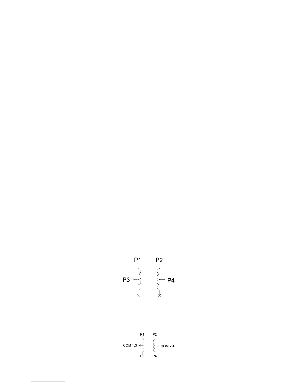
Step Motor Congurations
Step Motors can be congured as 4, 6, or 8 leads. Each conguration requires different currents.
Refer to the lead congurations and the procedures to determine their output current.
WARNING! Step motors will not run hot even when congured correctly. Damage may occur to
the motor is higher than specied current is used. Most specied motor currents are maximum
values. Care should be taken to not exceed these ratings.
6 Lead Motors
When conguring a 6 lead motor in a half-coil conguration (connected from one end of the
coil to the center tap), multiply the specied per Phase (or unipolar) current rating by 1.4 to de-
termine the current setting potentiometer value. This conguration will provide more torque at
higher speeds when compared to the series conguration.
When conguring the motor in a series conguration (connected from end to end with the cen-
ter tap oating) use the specied per phase (or unipolar) current rating to determine the current
setting potentiometer value.
July 2018

September 2012L010155 11
4 Lead Motors
Multiply the specied series motor current by 1.4 to determine the current adjustment potenti-
ometer value. 4 lead motors are usually rated with their appropriate series current, as opposed
to the Phase Current, which is the rating for 6 and 8 lead motors.
8 Lead Motors
Series Connection: When conguring the motor windings in series, use the per phase (or uni-
polar) current rating to determine the current setting potentiometer value.
Parallel Connection: When conguring the motor windings in parallel, multiply the per phase (or
unipolar) current rating by 2.0 to determine the current setting potentiometer value.
Note: After the current has been determined, according to the motor connections above, use
Table 3 to choose the proper setting for the current setting potentiometer.
July 2018July 2018

September 2012L010155 12
Connecting the Step Motor
Phase 1 and 3 of the Step Motor is connected between pins 1 and 2 on the motor connector
(TB2). Phase 2 and 4 of the Step Motor is connected between pins 3 and 4 on the motor con-
nector (TB2). The motors case can be grounded to pin 5 on the motor connector (TB2). Refer
to gures 2, 3, & 4 for TYPICAL APPLICATION HOOK-UP.
Note: The physical direction of the motor with respect to the direction input will depend on the
connection of the motor windings. To reverse the direction of the motor with respect to the direc-
tion input, switch the wires on Phase 1 and Phase 3.
WARNING! Do not connect or disconnect motor wires while power is applied!
Short-Circuit, Mis-Wire, and Current Conditions
If it is found that there is condition that causes on over current in the driver phase transistors, the
Red LED will turn on solid and power will be shut off to the motor. To reset the drive turn power
off, check wiring, and turn power back on.
Over-Temperature and Over-Voltage Conditions
If it is found that there is an over temperature on the internal heat sink, or an over voltage on the
motor bus voltage, the Red LED will blink and power will be shut off to the motor. To reset the
drive turn power off, check wiring, and turn power back on.
July 2018

September 2012L010155 13
Methods of Communication
There are two methods for sending commands to the DPN10601. One is to directly talk to the
DPN10601 by using Direct Talk Mode. This is usually used with a computer or PLC (Programmable
Logic Controller), where the computer or PLC gives the DPN10601 serial commands to off-load its
processor. For example: A PLC can utilize its outputs to toggle the DPN10601’s inputs and gain con-
trol of variable speeds, variable programs, variable distances, etc. Simply using the DPN10601 as
the intelligent pulse generator, a PLC can remove some of the tasks that were not meant for ladder
logic or any PLC processing time.
The second way to give commands to the DPN10601 is to use the software program SMC60WIN to
either manually control, or to write and send programs. This method is used when the DPN10601
is the main controller. For example: A DPN10601 can replace simple motion control and replace I/O
functional when minimal quantities of I/O are required to control specic machinery. Simple motion
proles that can operate with 6 or less inputs and 8 or less outputs can utilize a DPN10601 controller.
Baud Rate
A term used frequently is serial data communications, a “baud” is dened as the reciprocal of the
shortest pulse duration in a data word signal, including start, stop, and parity bits. This is often taken
to mean the same as “bits per second”, a term that expresses only the number of “data” bits per
second. Very often, the parity bit is included as an information or data bit. The DPN10601 accepts
a baud rate of 38400 only.
RS232 Protocol - Controller SW1 in RS232 Position
The DPN10601 is a DCE device, therefore it will transmit on pin 2 and receive on pin 3 of the DB9
RS-232 connector. The RS232 serial communication mode is single ended. This means that for each
signal there is one wire, and a common ground reference used by all the signals. The DPN10601
does not use handshaking, thus the CTS and RTS lines are internally connected, and the CD, DTR
and DSR lines are internally connected inside the DPN10601. The signal line maintains levels of
+5VDC to +15VDC and -5VDC to -15VDC. For a valid logic level in the controller, the voltage must
be at least +/- 3 volts. RS232 works at distances of up to 50 feet maximum. RS232 is susceptible
to electrical noise, and should not be used in noisy areas. Always use the shortest cable con-
nection possible. NOTE: Keep Controller wiring separated from motor cable/wiring.
RS485 Protocol - Controller SW1 in RS485 Position
The RS485 protocol mode is as follows; On board receivers will remain in active mode indenitely. Trans-
mitters must be turned off when the unit is not sending data, to prevent the line from sending and receiving
data at the same time. Therefore when the PC is transmitting data its driver will be turned on and each
of the units connected will have their drivers off. If they are requested to send data back to the PC, the
selected unit will turn it’s driver on to send the data and then turn it off after it has completed transmission.
Note: The above protocol is done internally between the converter and the DPN10601. The RS485 method
of communication allows increased noise immunity and increased communication distance of up to 4000
feet without repeaters. RS485 repeaters allow an additional 4000 feet per repeater. The DPN10601 is
designed for two wire conguration. The 2 wire conguration makes use of the tristate capabilities of RS485
to allow a single pair of wires to share transmit and receive signals for half duplex communications. This
“two wire” conguration (note that an additional ground conductor must be used) reduces cabling cost.
Note: Keep control wiring separated from motor cable/wiring.
Section 3: Controller Functions
July 2018

September 2012L010155 14
RS232 to RS485 for Multiple units or cables longer than 50ft
The DPN10601 can be connected to your PC serial port via a RS485 converter (model number:
485SD9TB sold separately). This converter will convert the RS232 voltage signals to the com-
patible RS485 differential signals. Only one converter box is needed per serial port. Contact
the factory or use the website www.anaheimautomation.com for RS485 converter information
and sales.
Terminating Resistor
To eliminate noise on the transmission lines or when using a 4000 ft. or longer cable, a terminat-
ing resistor is suggested. If used, the termination resistor need only be added to the last (furthest
from the converter box) DPN10601 in the network between pins A(-) and B(+) on the RS485
Terminal Block. The value of this resistor should be 120 ohms.
Axis Selection
Each DPN10601 is addressed using a programmable register allowing the PC to address up to
99 DPN10601’s from one port. The Default axis is “0”. To change the axis, use the SMC60WIN
software or the “~” command. To verify or check the axis, use the SMC60WIN software or the “%”
command. The axis designation is nonvolatile and will remain the same until changed by the user.
Controller Status LED
When powered and operated properly, the status LED will be green. When an error occurs, the
LED will change to RED, and an error code will be generated in the error code register. To read
and clear the error with software, click on the “Verify Parameters” button located in the “Motion
Tab”. To read and clear the error while in “Direct Mode”, use the error code “!” command. Once
the error has been read and cleared, the LED will return to green and the error code register will
be cleared to 0. Refer to the table on page 39 for a complete list of the error codes.
Technical Support
Everyone needs assistance on occasion. If you have problems using any of the equipment cov-
ered by this manual, please read the manual to see if it will answer your questions. Be sure to
look in the Trouble-shooting Section located near the back of this manual. If you need assistance
beyond what this manual can provide, you may call the factory direct for application assistance.
If possible, have this manual in hand. It is often helpful to have the controller connected to a
computer with the software installed.
July 2018

September 2012L010155 15
Move Number of Steps: This command causes the motion to start in the direction last specied.
This command will move the motor the number of steps given. (Range: 1 to 8388607)
Move to Position: The move to position command species the next absolute position to go to. The
DPN10601 controller automatically sets the direction and number of steps needed to go to that posi-
tion. (Range: -8388607 to +8388607)
Slew: The slew command will accelerate the motor up to maximum speed and continue to run at
that speed until reaching a registration mark, hard limit switch, soft limit switch, receiving a “.” (stop
hard) or “,” (stop soft) command.
Set Position: The set position command sets the position register to a designated value. The number
will be the new absolute position of the motor. The default value is 0. (Range: -8388607 to +8388607)
Limit Switch Inputs: The limit switch inputs are internally pulled up by a resistor making them normally
+5V. To activate the input, the pin must be grounded to (0VDC). All limit switch inputs are internally
clamped to +5V, thus allowing voltages of up to +24VDC to be used.
Hard Limit Inputs: When a hard limit switch is encountered, the motion will stop immediately. The
position counter will also cease counting. Hard limits are intended as an emergency stop for your
system. It should not be used to do any positioning type functions. These limits are directional.
Soft limit Inputs: These switches should be used exclusively for homing. Once positioned properly
with the appropriate parameters, it causes the motor to ramp down to the base speed before encoun-
tering the home limit switch. However, the soft limit switch will work for any type of motion command.
These limits are directional.
NOTE: Whenever a soft limit switch is activated, the motor will decelerate and run at base speed
during an indexing move, or stop during a slewing move. Be sure to come back past the soft limit
switch to set any origins, otherwise the motor will decelerate as it goes past the soft limit switch dur-
ing normal operation.
Home Limit Input: This switch is used to establish a position designated “home” or datum position
using the following: home to soft and home limit, or home to home limit. This limit is not directional.
Home to Soft, Home Limit (2 Switch Operation): This type of homing routine requires two ground-
ing type limit switched called home and soft. The rst limit switch seen is the soft limit. This will
decelerate the motor down to base speed. The motor will then continue to run at base speed until it
contacts the home limit switch input causing the motor to stop. The home limit switch activates as a
hard limit if a soft limit is not sensed. The soft limit is directional, meaning that it will work in only one
direction as specied. The soft limit switch will work for any type of motion command. The home
limit switch will work only for the two home motion commands.
NOTE: There should be sufcient distance between the two limit switches, as to let the motor reach
base speed.
Home to Home Limit (1 Switch Operation): This type of homing differs in that only one limit switch
is needed. In this homing routine the motor moves toward the home limit switch. When the home
limit switch is contacted the motor will ramp down to base speed, reverse direction and continue at
base speed until the limit switch is released. This is a good way to compensate for any backlash in
a system. It is also useful for minimizing the number of limit switches needed for homing.
NOTE: The home switch needs to be low during the entire deceleration and reversing time.
July 2018

September 2012L010155 16
Jog Inputs: The jog switch inputs are internally pulled up by a resistor making them normally +5 volts.
To activate the input, the pin must be grounded to (0VDC). All jog switch inputs are internally clamped to
+5V, thus allowing voltages of up to +24VDC to be used. Jog is a manual function. The user can select
the direction and speed (fast or slow) by grounding the appropriate combinations of inputs. To jog a mo-
tor, it is necessary to ground the jog input for the direction desired. For fast jog, both the fast input and
jog input for the appropriate direction must be low at the same time. By grounding one of the jog inputs,
the user causes the motor to run at base speed. When the fast input is grounded, the motor will then ac-
celerate to the programmed jog speed. The position register will keep track of the number of steps that
are taken during jogging. Once a +jog or a -jog function has been performed, the direction register will
retain the last direction of movement; that is, a subsequent go command will be in the same direction as
the last jog command.
Inputs: All inputs (except input 1) are internally pulled up by a resistor making them normally +5V. To
activate the input, the pin must be grounded to (0VDC). All inputs are internally clamped to +5V, thus al-
lowing voltages of up to +24VDC to be used. Six inputs are provided per axis. The inputs are TTL, CMOS
and 24V compatible. The inputs may be used to initiate a machine cycle, for inter-axis coordination (in
stored program mode), for operator intervention, for sensing a machine condition such as out of stock or
wait temperature to be reached, etc. A ground input will read a “0” and an open or high input will read as
a “1”. Input 1 is a special input that is capable of reading an analog voltage between 0 and +5VDC. Since
this input does not have a pull-up resistor, biasing of this input is needed if it is not used as an analog
input. Inputs 5 and 6 are used together with the thumbwheel switch. To use inputs 5 and 6, SW2 of the
controller must be in the IN5/6 position. If SW2 of the controller is in the TWS position, then these two
inputs are not connected to the input port of the processor.
Analog Input: Input 1 can be congured to read an analog voltage to either set the absolute position of
the motor or to set the maximum speed of the motor.
The set the position, when told via the go to analog position command, the input will read a voltage
between 0 and +5VDC and based on the “upper and lower” limits of the function, a move will occur to a
calculated position between the two limits. The motor must nish the move before it can be told to read
the input again for the next position. For example, if the lower limit is set to 0 and the upper limit is set
to 5000 and the analog position is set at +2.0VDC, then the motor will move to position 2000. Changing
the lower limit to 1000 and the voltage to +3.2VDC, the motor will move to position 3560. See examples
below for calculations of the analog inputs. (Range of limits: 0 to 65535 and the lower limit < upper limit)
To set the max speed, when told via the set analog speed command the input will read a voltage between
0 and +5VDC, and based on the “upper and lower” limits of the function, a max speed can be obtained
based on a calculated frequency between the two points. The speed however can not be changed when
the DPY50601 is busy (moving). See examples below for calculations of the analog inputs. (Range of
limits: 0 to 50000 and the lower limit < upper limit)
Outputs: Eight outputs are provided per axis. Outputs may be used to operate relays, coolant valves, air
cylinders, or, with the correct interfacing, any electronically controlled device. The outputs can drive all
types of common peripheral power loads, including lamps, relays, solenoids, LED’s, printer heads, and
heaters. For inductive loads, it will be necessary to connect a clamping diode (refer to specication sec-
tion) from the output to the power source in order to provide adequate y-back protection. The outputs
are current sinking, open collector darlingtons. They are capable of sinking up to 100mA per output with
voltages up to 40VDC. Turning an output on will pull the output pin to ground and turning an output off
will make the output pin open. Output 1 has a special function (output on the y) that will enable it to be
triggered at a certain absolute position during a move. Output 8 has a special function that will trigger
when the encoder retries function fails.
Analog Calculations Example 1: Example 2:
(Upper-Lower) * (Voltage/5) = X (5000 - 0) * (2/5) = 2000 (5000 - 1000) * (3.2/5) = 2560
Lower + X = Position or Frequency 0 + 2000 = 2000 1000 + 2560 = 3560
July 2018

September 2012L010155 17
Output on the y: This special function enables output 1 to turn on during a relative index or absolute
move. There are three critical portions of information needed to make this function work correctly. First,
output 1 will turn on (0VDC) for a preset delay of 50uS at a specic absolute position set by the 1st output
position command. Second, the output can then repeat this after a preset amount of steps set by the
number of steps between outputs command, and third a predetermined amount of times to set the output
is required by the number of outputs command which determines the preset amount of times to trigger
the output. So if you start at position 0 and want to move to an absolute position of 10,000, you can set
output 1 to turn on at position 2000, and every 1000 steps after that 5 times. So at position 2000, 3000,
4000, 5000, and 6000 output 1 will turn on for 50uS. To only have the output turn on at one position set
both the “number of steps between outputs” and the “number of outputs” commands to 0. This function
must be enabled, and will only work during a relative index or absolute position move. The output will
trigger while going in either direction. If you do not want the output to trigger in the negative direction, the
function must be turned off before the index move is started.
Index on the y: This special function uses Input 2 when a motor is slewing to move a predetermined
amount of steps, set with the registration index command, before stopping. This function must be enabled,
and will only work during a slew move. The registration index must be set before movement begins.
(Range: 1 to 8388607)
End of Program: The end of program command, used within a stored program, stops execution of the
program. This command must be used at the end of all programs.
Wait: In stored program mode, the wait command pauses the program for the specied number of mil-
liseconds. (Range:1 to 65535)
If/Then Statements: The if/then statements are conditional based on the values preset in the program.
The user can either test each individual input or all inputs at once. If the input or input register matches
the given value or values, then the program will execute the next line. If the input or input register does
not match the given value, the program will skip the next line and execute the following line. An open
input is read as a 1, and a grounded input is read as a 0.
Branching or Go To statements: The go to instruction will have the program jump to the given label. If
no label is in the program, it will error when trying to send.
Return from Subroutine: This function can be placed anywhere in the program as long as a go to state-
ment has already been executed. The program will jump back to the last go to statement encountered
and executed the next line in the program.
Inner and Outer Loop: The loop instructions allow the user to loop a program a variable number of times.
The program will loop to the designated label location of the program. However, the label must always
be at a lower line number than the loop instruction itself. You can only nest inner loops inside an outer
loop. You may not nest an inner loop inside an inner loop, or an outer loop inside an outer loop. Multiple
nested inner loops are allowed in one outer loop.
Finish Move: When writing a program, the nish move command is used directly after every motion
command. When using this command, the DPN10601 internally generates a busy signal and will wait
until the move is complete before executing any further commands. Unless the nish move command is
used, the DPN10601 will continue to execute the program. If it encounters a command that cannot be
used when the motor is moving, the DPN10601 will error and stop the program prematurely.
Repeat Last Move: This command will move the motor the number of steps given in the last indexing
move. This command will not work correctly if the encoder auto correct function is enabled.
July 2018July 2018July 2018

September 2012L010155 18
Encoder Commands: The DPN10601 controller is capable of using a quadrature incremental encoder
with A and B channels.
Encoder Auto Correct: This command will enable or disable the encoder feature of the DPN10601.
When enabled, the encoder function will compare the desired position with the actual encoder position.
If it is not in the correct position a correction move will be made.
Encoder Delay: This sets the wait time, which is a specied number of milliseconds after a relative
index or absolute move is nished, prior to reading the encoder. This is used to remove the ringing that
might be associated with the mechanics of the system. (Range: 0 to 65535)
Encoder Motor Ratio: This represents the ratio for the number of encoder pulses to one motor step.
This ratio must be a whole number. For example, given a 1000 line quadrature encoder and a 400 step/
revolution motor, the motor ratio is (1000 * 4)/400 = 10 (Range: 1 to 255 and must be a whole number).
Encoder Retries: This is the number of times the DPN10601 will try to auto correct the motor shaft
position before producing an error. When the error is produce, Output 8 is triggered. (Range: 0 to 255)
Encoder Window: This is the allowable error in encoder pulses (either plus or minus) from the desired
position that is allowed before the motor auto corrects. (Range: 0 to 255)
Thumbwheel Index: This special function allows a thumbwheel with up to 7 decades to be used with
the DPN10601 to set a relative index. To use the thumbwheel, SW2 must be in the TWS position or
the thumbwheel will be disabled.
Acceleration/Deceleration: The acceleration and deceleration are the same value. The acceleration
is entered directly as steps/sec2and controls the time that the motor will take to move from base speed
to max speed, and from max speed to base speed. The higher the value, the faster the motor will ac-
celerate. The same principal applies for the deceleration which is controlling the time it takes to go from
the max speed to base speed. (Range: 100 to 9,999,999)
Base Speed: The base speed is the speed at which motion starts and stops. It is entered directly as
the number of steps per second. This speed must always be less than the max speed and jog speed.
(Range: 1 to 5000)
Max Speed: The max speed is the top speed the user wants the motor to run. This speed must always
be greater than the base speed. It is entered directly as the number of steps per second. (Range: 1
to 50000)
Jog Speed: The jog speed sets the fast jog rate. Jog (+/-) is used to run at base speed. The FJOG
pin when grounded, will ramp the motor to the set jog speed. This speed must always be greater than
the base speed. It is entered directly as the number of steps per second. (Range: 1 to 50000)
Motor Current: This command will control the ON/OFF output which is designed to connect to the ON/
OFF input of Anaheim Automation’s step motor drivers. To energize and allow current to ow through
the coil of the motor, set the value to on. To de-energize and turn the current off to the motor, set the
value to off. This is dedicated output and not controlled with the output register.
Verify: The verify command causes the DPN10601 controller to send data back to the PC or PLC. The
data is sent as an ASCII decimal string followed by a carriage return and a line feed. The verify com-
mands are shown in the table on page 34.
July 2018

September 2012L010155 19
The SMC60WIN software is a handy utility that supports Anaheim Automation’s line of DPN10601’s
step motor controllers. Connecting your PC to the DPN10601, via a serial cable, the SMC60WIN
software can easily perform the following tasks:
• Exercise and monitor the DPN10601 controller
• Write and edit stored programs for standalone operation
• Directly communicate with the DPN10601 controller
Section 4: SMC60WIN Software
Installation
Software
• The SMC60WIN is supplied on a CD, containing the setup program and the SMC60WIN
software, DPN10601 manual and sample programs.
• SMC60WIN software is compatible with all versions of Windows including Windows
2000, Windows XP, Vista, and Windows 7.
Windows 95/98/NT/ME/2000/XP Installation
Option 1
1. Insert the CD into the drive
2. From the Program Manager select Start │ Run
3. Enter D:\setup and click OK - use the appropriate drive letter (i.e. Dor E)
Option 2
1. Open Windows Explorer
2. Open CD Drive Folder (D: or E:)
3. Double Click the setup Icon
Getting Started
1. Double click on the SMC60WIN icon to run the SMC60WIN software.
2. Apply power to the DPN10601 controller.
3. Set the appropriate communication setting by selecting Setup │ Com Port Settings
from the menu bar. (Ctrl+M is a shortcut)
4. Set the appropriate axis setting by selecting Setup │ Axis from the menu bar. (Ctrl+A
is a shortcut)
5. Establish communications with the DPN10601 by clicking on the Connect Icon, or select
Setup│Connect from the menu bar. If the unit is connected properly, the program will
notify you when communication has been established. (Ctrl+C is a shortcut)
July 2018
September 2012L010155 20
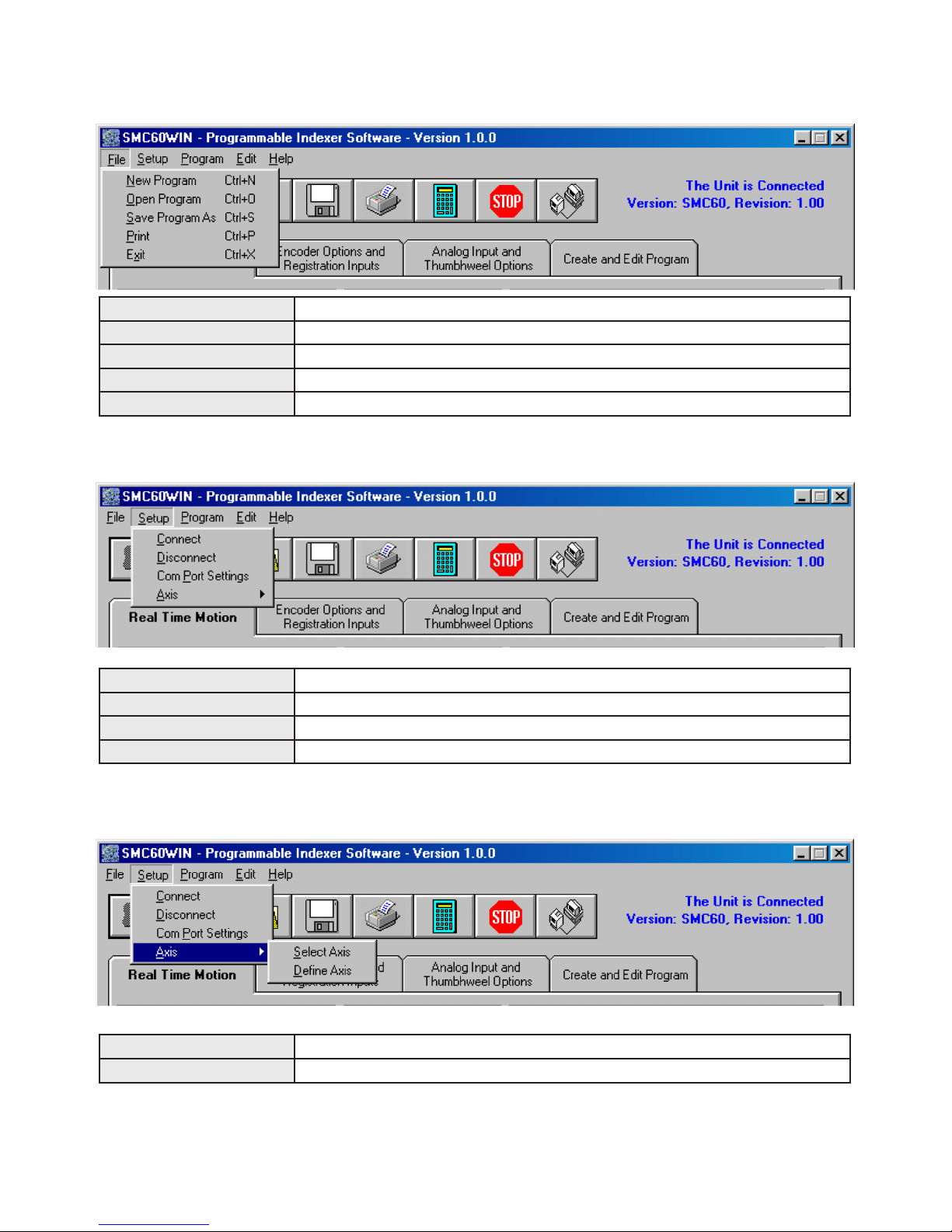
File Menu
Setup Menu
Setup - Axis Menu
Connect Establish communications with the controller.
Disconnect Release the COM port for other devices to use.
Com Port Settings Select COM port.
Axis Set axis selection and stored axis of the controller.
Select Axis Sets the axis select parameter in the SMC60WIN software. (1-99)
Dene Axis Sets the programmable address in the controller. (1-99)
New Program Start editing a new program.
Open Program Open an existing program from disk.
Save Program As Save the current program to disk.
Print... Print the current program.
Exit Exit the SMC60WIN software.
July 2018
Table of contents
Other Anaheim Automation DC Drive manuals

Anaheim Automation
Anaheim Automation MBC25SI1TB User manual

Anaheim Automation
Anaheim Automation DPD75601 User manual

Anaheim Automation
Anaheim Automation DPD75601 User manual

Anaheim Automation
Anaheim Automation MBC25081-06 User manual

Anaheim Automation
Anaheim Automation DPE25601 User manual

Anaheim Automation
Anaheim Automation DPE25611 User manual


