manuals.online logo
Brands
  1. Home
  2. •
  3. Brands
  4. •
  5. Analog Devices
  6. •
  7. Motherboard
  8. •
  9. Analog Devices Linear Technology DC2472A Quick setup guide

Analog Devices Linear Technology DC2472A Quick setup guide

1
dc2472af
DEMO MANUAL DC2472A
DESCRIPTION
18-CELL STIMULUS BOARD
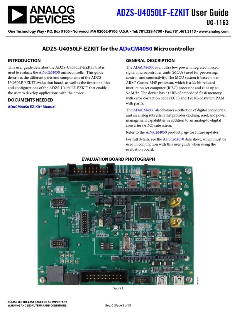
Demonstration circuit 2472A is a USB-powered resistor-
string, voltage ladder with variable output. The DC2472A
provides a simple battery stack simulator for connection
directly to most of Linear Technology’s LTC68xx “battery
stack monitor” demo boards.
Using the 5V from a USB charger, the DC2472 generates
an isolated high voltage from ~25V to ~75V, applied to
a resistor string generating 18 voltages taps. These taps
provide a simulation of a string of series connected bat-
tery cells, each tap pair providing nominally the same
virtual cell voltage. The input voltage to the resistor string
is adjustable by an on-board potentiometer to furnish a
divided output voltage in a range of about 1.5V-4.2V per
cell to demonstrate operation at conditions comparable
to a wide range of cell chemistries.
CONNECTION TO AN LTC68XX DEMO-BOARD
1. The back side of the DC2472A shows where the
LTC68xx demo board connectors should be attached.
Simply line up the finger contacts with the associated
screw terminal connector according to whether the
connector is a 16- or 19-contact model. The screws
for securing the connections should be facing the com-
ponent side of the DC2472A. Torque the 16- or 19-posi-
tion connections to 0.2-0.25Nm. A 22-contact adapter L, LT, LTC, LTM, Linear Technology and the Linear logo are registered trademarks of Analog
Devices, Inc. All other trademarks are the property of their respective owners.
(e.g. DC2701A) should be torqued to 0.22-0.25Nm.
See Figure 1 for example installations.
2. In the case of a 15-cell demo (e.g. for LTC6812), the
pinout requires every sixth tap pair to be shorted over.
To accomplish this, place JP19, JP20, and JP21 to the
“15” position. In all other usages, leave those jumpers
in the ‘18’position. Note that cell voltages will increase
20% with placement of jumpers in the “15” position
due to the reduced division factor.
3. A USB to USB MICRO-B cable (like non-Apple cell
phone charger) provides a simple means of powering
the DC2472A from a 1A USB charger (some computer
ports may not provide adequate current for stable
output levels). Alternatively, a 5V bench power supply
can be connected to the power input turrets (+5V &
+5V COM) with clip-leads. Note that the +5V connec-
tions are isolated with respect to the GND turret of the
DC2472A, so the +5V COM and GND cannot be used
interchangeably.
WARNING –THIS BOARD GENERATES VOLTAGE POTEN-
TIALS UP TO 80V
Design files for this circuit board are available at
http://www.linear.com/demo/DC2472A
Figure 1. Output Connection Options
Typical DC2701 Adapter UsageTypical 12-Cell Demo Typical 15- or 18-Cell Demo
Downloaded from Arrow.com.
2
dc2472af
DEMO MANUAL DC2472A
QUICK START PROCEDURE
1. Power up the DC2472A from the USB cable or bench
supply.
2. Once powered, the Blue LED1 should illuminate.
3. Adjust potentiometer to provide a desired equivalent
cell voltage as shown in Figure 2. Note that there will
be some variation in voltages amongst “cells” due to
component tolerances.
4. Operate the LTC68xx demo as applicable. Note that
resistor-string battery simulations (and DC2472A in
particular) cannot generally generate currents suitable
for properly demonstrating cell-balancing activity.
5. Jumpers JP0 through JP18 may be used to discon-
nect particular tap signals for demonstrating ‘open-
wire’ scenarios. Relocating a particular jumper to the
NC position will disconnect a cell path to simulate a
broken connection.
Figure 2. Cell Voltage Setting
Downloaded from Arrow.com.Downloaded from Arrow.com.
3
dc2472af
DEMO MANUAL DC2472A
THEORY OF OPERATION
The DC2472A is a resistor-string voltage-divider ladder
powered by a variable voltage. A block diagram is shown
in Figure 3 and shows the key functional elements. The
heart of the circuit is an LT8302 isolated flyback converter
that produces both about 40V and 80V from a 5V source
such as a USB charger. The source 5V does not share
a galvanic connection to the equivalent cell-stack being
simulated so that many units can be operated without any
‘ground-loop’ fault currents. The 40V powers an LT6650
amplifier whose 15V output is scaled by a potentiometer
to create a variable voltage. The variable voltage is ampli-
fied 5x by an LTC6090 op amp that is powered from the
80V. The LTC6090 drives an 18-tap resistor ladder to
generate the equivalent series-connected cell voltages.
Each tap pair includes a significant capacitance to pro-
vide steady voltage in the presence of digitizing activity
by the demo board that is being powered. The amplifier
is decoupled and stabilized to operate with the capacitive
load but can still quickly respond to larger load demands
(i.e. the supply dynamics of the battery monitoring cir-
cuit being powered). To also support 6-cell and 12-cell
demonstrations, LTC6090 op amps also buffer 1/3 and
2/3 of the main LTC6090 voltage to provide stabilization
at those points in the ladder that might have to supply
current to a monitoring demo. To support a 15-cell demo,
every 6th cell divider can be shorted over with a jumper
(note that 15-cell demo circuits are designed to accept
their cell inputs in a compatible pinout with 3 zero-volt
cells). The lower voltage LTC6090 units include voltage
reduction Zener diodes to minimize heating of the IC die
if driving load current.
ISOLATED
FLYBACK
DC/DC
CONVERTER
15V
REFERENCE
VARIABLE
ATTENUATOR
AMPLIFIER
A=5
w/CLOAD
COMP.
AMPLIFIER
A=1
w/CLOAD
COMP.
AMPLIFIER
A=1
w/CLOAD
COMP.
3 RESISTOR STRING
15/18 RESISTOR STRING
18 TAPS
5V 80V 25V-75V TAP18
TAP12TAP6
Figure 3. Block Diagram of the DC2472A
Downloaded from Arrow.com.Downloaded from Arrow.com.Downloaded from Arrow.com.
4
dc2472af
DEMO MANUAL DC2472A
 LINEAR TECHNOLOGY CORPORATION 2017
LT 0717 • PRINTED IN USA
DEMONSTRATION BOARD IMPORTANT NOTICE
Linear Technology Corporation (LTC) provides the enclosed product(s) under the following AS IS conditions:
This demonstration board (DEMO BOARD) kit being sold or provided by Linear Technology is intended for use for ENGINEERING DEVELOPMENT
OR EVALUATION PURPOSES ONLY and is not provided by LTC for commercial use. As such, the DEMO BOARD herein may not be complete
in terms of required design-, marketing-, and/or manufacturing-related protective considerations, including but not limited to product safety
measures typically found in finished commercial goods. As a prototype, this product does not fall within the scope of the European Union
directive on electromagnetic compatibility and therefore may or may not meet the technical requirements of the directive, or other regulations.
If this evaluation kit does not meet the specifications recited in the DEMO BOARD manual the kit may be returned within 30 days from the date
of delivery for a full refund. THE FOREGOING WARRANTY IS THE EXCLUSIVE WARRANTY MADE BY THE SELLER TO BUYER AND IS IN LIEU
OF ALL OTHER WARRANTIES, EXPRESSED, IMPLIED, OR STATUTORY, INCLUDING ANY WARRANTY OF MERCHANTABILITY OR FITNESS
FOR ANY PARTICULAR PURPOSE. EXCEPT TO THE EXTENT OF THIS INDEMNITY, NEITHER PARTY SHALL BE LIABLE TO THE OTHER FOR
ANY INDIRECT, SPECIAL, INCIDENTAL, OR CONSEQUENTIAL DAMAGES.
The user assumes all responsibility and liability for proper and safe handling of the goods. Further, the user releases LTC from all claims
arising from the handling or use of the goods. Due to the open construction of the product, it is the user’s responsibility to take any and all
appropriate precautions with regard to electrostatic discharge. Also be aware that the products herein may not be regulatory compliant or
agency certified (FCC, UL, CE, etc.).
No License is granted under any patent right or other intellectual property whatsoever. LTC assumes no liability for applications assistance,
customer product design, software performance, or infringement of patents or any other intellectual property rights of any kind.
LTC currently services a variety of customers for products around the world, and therefore this transaction is not exclusive.
Please read the DEMO BOARD manual prior to handling the product. Persons handling this product must have electronics training and
observe good laboratory practice standards. Common sense is encouraged.
This notice contains important safety information about temperatures and voltages. For further safety concerns, please contact a LTC application
engineer.
Mailing Address:
Linear Technology
1630 McCarthy Blvd.
Milpitas, CA 95035
Copyright © 2004, Linear Technology Corporation
Downloaded from Arrow.com.Downloaded from Arrow.com.Downloaded from Arrow.com.Downloaded from Arrow.com.
Other Analog Devices Motherboard manuals

Analog Devices AD9574 Quick start guide

Analog Devices

Analog Devices AD9574 Quick start guide

Analog Devices ADuC7026 Supplement

Analog Devices

Analog Devices ADuC7026 Supplement

Analog Devices EVAL-ADPD2140Z User manual

Analog Devices

Analog Devices EVAL-ADPD2140Z User manual

Analog Devices EVAL-ADAU1401EBZ User manual

Analog Devices

Analog Devices EVAL-ADAU1401EBZ User manual

Analog Devices EVAL-ADPDM3Z User manual

Analog Devices

Analog Devices EVAL-ADPDM3Z User manual

Analog Devices DC2973A Quick setup guide

Analog Devices

Analog Devices DC2973A Quick setup guide

Analog Devices AD9956/PCB User manual

Analog Devices

Analog Devices AD9956/PCB User manual

Analog Devices EVAL-ADAQ4001 User manual

Analog Devices

Analog Devices EVAL-ADAQ4001 User manual

Analog Devices EVAL-AD5162SDZ User manual

Analog Devices

Analog Devices EVAL-AD5162SDZ User manual

Analog Devices DC336 User manual

Analog Devices

Analog Devices DC336 User manual

Analog Devices ADP5360 User manual

Analog Devices

Analog Devices ADP5360 User manual

Analog Devices EVAL-AD7606C18FMCZ User manual

Analog Devices

Analog Devices EVAL-AD7606C18FMCZ User manual

Analog Devices DC2685B-KIT Quick setup guide

Analog Devices

Analog Devices DC2685B-KIT Quick setup guide

Analog Devices DC2629A Quick setup guide

Analog Devices

Analog Devices DC2629A Quick setup guide

Analog Devices EVAL-LT8350-AZ User manual

Analog Devices

Analog Devices EVAL-LT8350-AZ User manual

Analog Devices ADMV8818-EVALZ User manual

Analog Devices

Analog Devices ADMV8818-EVALZ User manual

Analog Devices Blackfin Landscape LCD EZ-Extender... User manual

Analog Devices

Analog Devices Blackfin Landscape LCD EZ-Extender... User manual

Analog Devices EV-ADF5355SD1Z User manual

Analog Devices

Analog Devices EV-ADF5355SD1Z User manual

Analog Devices EV-ADF5904SD2Z User manual

Analog Devices

Analog Devices EV-ADF5904SD2Z User manual

Analog Devices ADMV1013-EVALZ User manual

Analog Devices

Analog Devices ADMV1013-EVALZ User manual

Analog Devices ADP5055-EVALZ User manual

Analog Devices

Analog Devices ADP5055-EVALZ User manual

Analog Devices EVAL-AD5252SDZ User manual

Analog Devices

Analog Devices EVAL-AD5252SDZ User manual

Analog Devices EVAL-AD5165DBZ User manual

Analog Devices

Analog Devices EVAL-AD5165DBZ User manual

Analog Devices EVAL-ADP2311 User manual

Analog Devices

Analog Devices EVAL-ADP2311 User manual

Popular Motherboard manuals by other brands

AOpen AX5TC user guide

AOpen

AOpen AX5TC user guide

IEI Technology KINO-AA750-i2 user manual

IEI Technology

IEI Technology KINO-AA750-i2 user manual

Gigabyte MD71-HB0 Quick reference guide

Gigabyte

Gigabyte MD71-HB0 Quick reference guide

Trinamic TMCM-1617-BB manual

Trinamic

Trinamic TMCM-1617-BB manual

NXP Semiconductors PN7160 user manual

NXP Semiconductors

NXP Semiconductors PN7160 user manual

Asus Z87-EXPERT user manual

Asus

Asus Z87-EXPERT user manual

MSI MS-CF02 user guide

MSI

MSI MS-CF02 user guide

Infinion EVAL KIT HPD G1 SiC Quick start manual

Infinion

Infinion EVAL KIT HPD G1 SiC Quick start manual

M5Stack M5StickC user manual

M5Stack

M5Stack M5StickC user manual

Foxconn H77MXV Series user manual

Foxconn

Foxconn H77MXV Series user manual

ASROCK IMB-V1000 Guide

ASROCK

ASROCK IMB-V1000 Guide

Supermicro X11OP Series user guide

Supermicro

Supermicro X11OP Series user guide

iFix RT809 Series manual

iFix

iFix RT809 Series manual

Gigabyte H310M S2V user manual

Gigabyte

Gigabyte H310M S2V user manual

Texas Instruments LMR51450 EVM user guide

Texas Instruments

Texas Instruments LMR51450 EVM user guide

ASROCK H110M-DGS user manual

ASROCK

ASROCK H110M-DGS user manual

Intel BLKDQ965GFEKR Technical product specification

Intel

Intel BLKDQ965GFEKR Technical product specification

ASROCK H55 PRO - V1.0 user manual

ASROCK

ASROCK H55 PRO - V1.0 user manual

manuals.online logo
manuals.online logoBrands
  • About & Mission
  • Contact us
  • Privacy Policy
  • Terms and Conditions

Copyright 2025 Manuals.Online. All Rights Reserved.