Analytica GmbH AnaGate CAN quattro User manual

1 © 2008-2009, Analytica GmbH, D-76137 Karlsruhe, Vorholzstr. 36 18.05.2009
M
MA
AN
NU
UA
AL
L
A
AN
NA
AG
GA
AT
TE
E
C
CA
AN
N
U
UN
NO
O/
/D
DU
UO
O/
/Q
QU
UA
AT
TT
TR
RO
O
ANALYTICA
GmbH
Vorholzstrasse 36 Tel. +49 721 35043-0 E-mail: info@analytica-gmbh.de
D-76137 Karlsruhe Fax: +49 721 35043-20 WWW: http://www.analytica-gmbh.de

2 © 2008-2009, Analytica GmbH, D-76137 Karlsruhe, Vorholzstr. 36 18.05.2009
Revision History
Version Date Changes
1.0 01.03.2008 Initial version
1.1 01.08.2008 Integration of AnaGate uno
1.2 17.04.20098 Integration of AnaGate quattro
1.3 18.05.2009 More detailed description of factory reset.

3 © 2008-2009, Analytica GmbH, D-76137 Karlsruhe, Vorholzstr. 36 18.05.2009
Contents
1 Introduction.................................................................................................................................................... 6
1.1 Description............................................................................................................................................. 6
1.2 Features................................................................................................................................................. 6
1.3 Specification.......................................................................................................................................... 7
1.4 Scope of delivery.................................................................................................................................. 8
1.5 Interfaces and plugs............................................................................................................................. 9
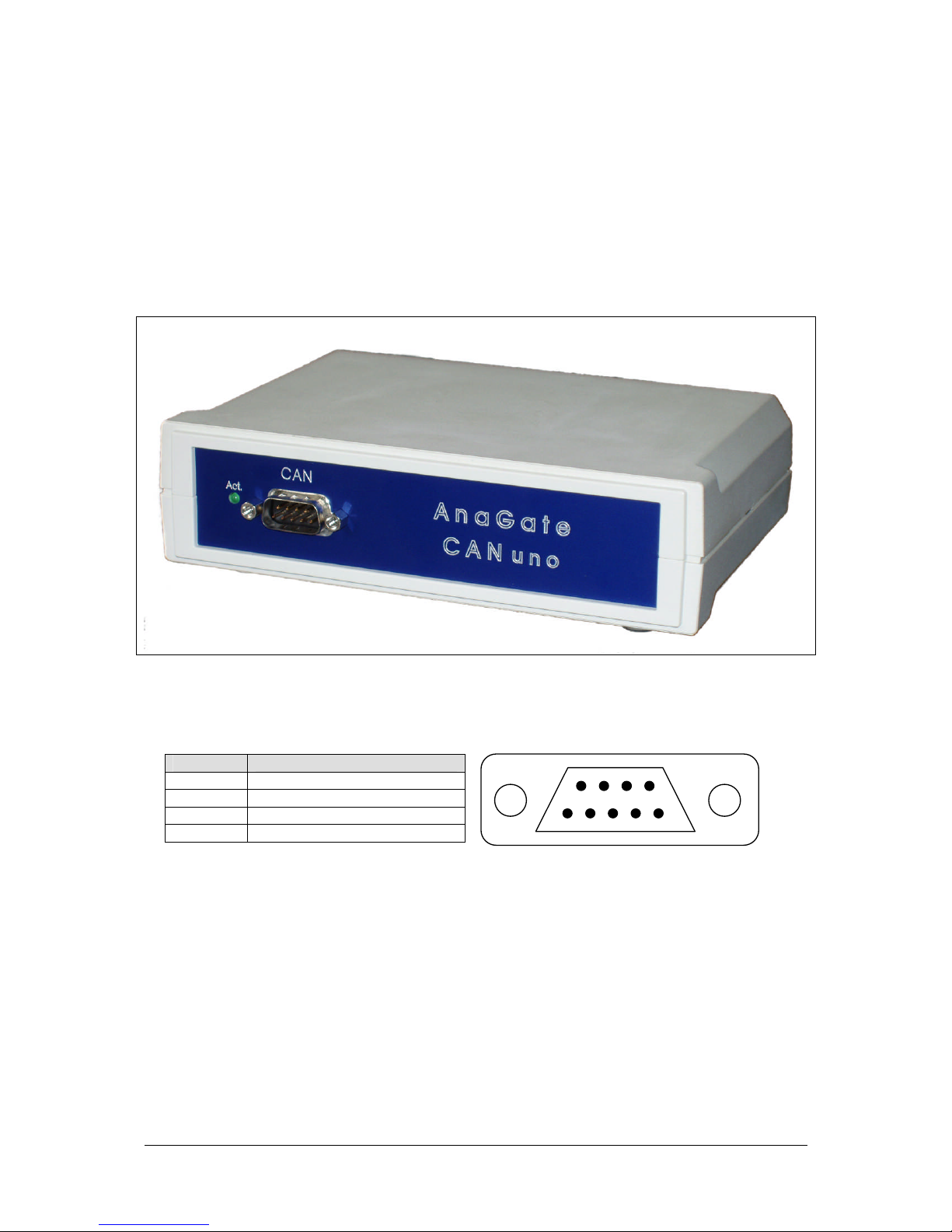
1.5.1 AnaGate CAN uno - front view ................................................................................................... 9
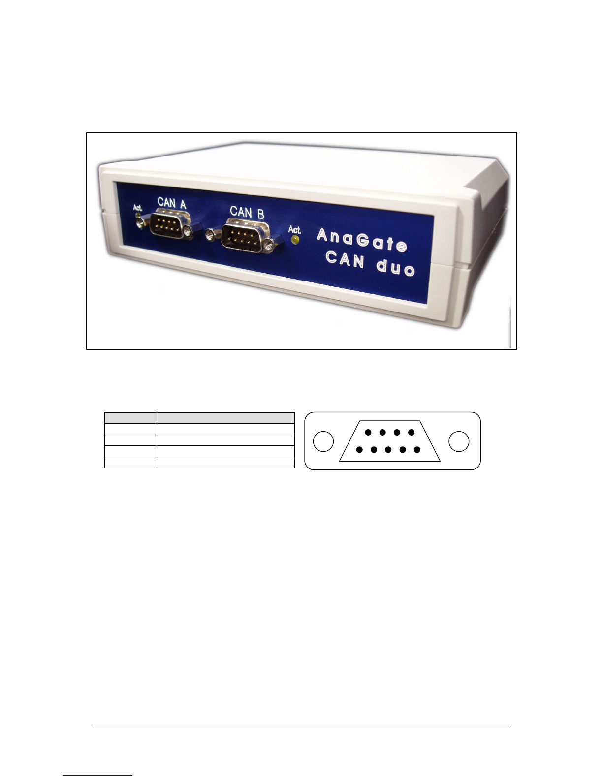
1.5.2 AnaGate CAN duo - front view ................................................................................................. 10
1.5.3 AnaGate CAN Quattro –front view.......................................................................................... 11
1.5.4 AnaGate CAN uno / AnaGate CAN duo –rear view............................................................. 12
2 Configuration............................................................................................................................................... 14
2.1 Initial installation.................................................................................................................................. 14
2.2 TCP/IP settings................................................................................................................................... 15
2.3 CAN settings........................................................................................................................................ 16
2.4 Firmware update................................................................................................................................. 17
2.5 Factory reset........................................................................................................................................ 17
2.5.1 Examining the TCP/IP settings................................................................................................. 18
2.6 The digital inputs and outputs........................................................................................................... 18
2.6.1 Connecting the digital inputs..................................................................................................... 19
2.6.2 Connecting the digital outputs .................................................................................................. 19
3 Application Scenarios ................................................................................................................................ 21
3.1 AnaGate CAN Gateway in gateway mode...................................................................................... 21
3.2 AnaGate CAN Gateway in bridge mode ......................................................................................... 22
4 Questions and Troubleshooting ............................................................................................................... 24
4.1 No LAN connection ............................................................................................................................ 24
4.2 No TCP/IP connection ....................................................................................................................... 24
4.3 Firewall................................................................................................................................................. 25

4 © 2008-2009, Analytica GmbH, D-76137 Karlsruhe, Vorholzstr. 36 18.05.2009
Charts
Chart 1-1: AnaGate CAN uno: front view..................................................................................................... 9
Chart 1-2: AnaGate CAN duo: front view................................................................................................... 10
Chart 1-3: AnaGate CAN quattro: rear view.............................................................................................. 11
Chart 1-4: AnaGate CAN Gateway: rear view .......................................................................................... 12
Chart 2-1: Browser interface (AnaGate CAN duo)................................................................................... 14
Chart 2-2: Browser interface: tcp/ip settings (AnaGate CAN duo)......................................................... 15
Chart 2-3: Browser interface: CAN settings (AnaGate CAN duo).......................................................... 17
Chart 2-4: pin layouts of the the digital inputs and outputs..................................................................... 19
Chart 2-5: Example for connecting the digital outputs............................................................................. 20
Chart 3-1: AnaGate CAN Gateway in gateway mode.............................................................................. 21
Chart 3-2: AnaGate CAN Gateway in bridge mode ................................................................................. 22
Tables
Table 1-1: AnaGate CAN uno: CAN plug PIN layout...................................................................................... 9
Table 1-2: AnaGate CAN duo: CAN plug PIN layout.................................................................................... 10
Table 1-3: AnaGate CAN quattro: CAN plug PIN layout .............................................................................. 11

5 © 2008-2009, Analytica GmbH, D-76137 Karlsruhe, Vorholzstr. 36 18.05.2009

6 © 2008-2009, Analytica GmbH, D-76137 Karlsruhe, Vorholzstr. 36 18.05.2009
1 Introduction
This manual describes the AnaGate models AnaGate CAN uno, AnaGate CAN duo and
AnaGate CAN quattro. The three devices essentially differ in the number of existing CAN
interfaces and are uniformly called "AnaGate CAN Gateway” in the following, if it is not
necessary to differentiate.
1.1 Description
The AnaGate CAN Gateway connects a PC, a embedded PC or other general device to up
to four CAN busses via the TCP/IP network protocol. The AnaGate CAN Gateway basically
works as a CAN master with now own CAN identifier on the bus.
For this reason the AnaGate CAN uno provides an ethernet interface and a single electrically
isolated CAN interface. The AnaGate CAN duo provides an ethernet interface and two
independent electrically isolated CAN interfaces. The AnaGate CAN quattro provides an
ethernet interface and four independent electrically isolated CAN interfaces.
Controlling and configuration of a AnaGate CAN Gateway is made through TCP/IP. The
application protocol is described detailed in the document „Manual AnaGate TCP/IP
communication“. Thus the access to the device can be programmed via native calls to the
TCP/IP socket interface. This means that any communication partner with a LAN interface is
able to communicate to the device. Accessing the AnaGate CAN Gateway with the supplied
windows application library (DLL) is much comfortable and can be used with a conventional
programming language.
In bridge mode the AnaGate CAN Gateway can interconnect two physically independent
CAN networks via LAN/Ethernet (LAN bridge mode). The AnaGate CAN duo and AnaGate
CAN Quattro can additionally interconnect two internal CAN interfaces (internal bridge
mode). With the coupling over LAN/Ethernet is possible to connect separate CAN buses with
different baud rates over long distances.
1.2 Features
Supports CAN send and receive commands for all CAN devices on one, two or four
independent CAN interfaces
Variable CAN bus speed (10, 20, 50, 62.5, 100, 125, 250, 500, 800 or 1000 kbps)

7 © 2008-2009, Analytica GmbH, D-76137 Karlsruhe, Vorholzstr. 36 18.05.2009
Configurable bus termination for each CAN interface.
Coupling of two independent CAN networks via the internal CAN/CAN bridge (only
AnaGate CAN duo and AnaGate CAN quattro)
Separate plug for voltage supply
System is addressed using a proprietary TCP/IP protocol
Static or dynamic assignment (DHCP) of IP addresses
4 digital inputs and outputs, which can be accessed via LAN/Ethernet
1.3 Specification
Measurements:
Length: approx. 155 mm
Width: approx. 105 mm
Height: approx. 40 mm
Weight: approx.175 g
CAN Bus:
Baud rate: 10, 20, 50, 62.5, 100, 125, 250, 500, 800 or 1000 kbps,
software configuration
CAN controller: 1x Microchip MCP 2515 (AnaGate CAN uno)
2x Microchip MCP 2515 (AnaGate CAN duo)
4x Microchip MCP 2515 (AnaGate CAN quattro)
CAN interface: 1x ISO 11898-2, galvanically decoupled (AnaGate CAN uno)
2x ISO 11898-2, galvanically decoupled (AnaGate CAN duo)
4x ISO 11898-2, galvanically decoupled (AnaGate CAN
quattro)
Interface: 1x DB9 plug incl. CAN_H and CAN_L (AnaGate CAN uno)
2x DB9 plug incl. CAN_H and CAN_L (AnaGate CAN duo)
4x pluggable clamp (4-pole) incl. CAN_H and CAN_L
(AnaGate CAN quattro)
Digital IO:
Inputs: 4, galvanic decoupled (3,3 –24V)
Outputs: 4, galvanic decoupled (3,3 –24V, Iges max = 0,5A)
LAN Interface:
Baud rate: 10/100 Mbps
TCP/IP: Static or dynamic (DHCP) IP address
Interface: RJ45 socket

8 © 2008-2009, Analytica GmbH, D-76137 Karlsruhe, Vorholzstr. 36 18.05.2009
Voltage Supply:
Voltage: 9V-28V direct current
Current consumption max. 350 mA (9V) without plugged USB consumers
Ambient Temperature:
Storage: 0 .. 85° C
In operation: 0 .. 55° C
1.4 Scope of delivery
The AnaGate CAN Gateway is supplied with the following components:
1x AnaGate CAN Gateway
1x CD with manual, DLL and CANopen driver for CANFestival
1x 1,8 m Cat. 5 LAN cable
1x 10 pole Wago plug connector
4x 4 pole plug connector for CAN interface (only AnaGate CAN qauttro)
1 x plug-in power supply unit (optional, compatible with country of delivery)
1x 2 pole Wago plug connector (optional)

9 © 2008-2009, Analytica GmbH, D-76137 Karlsruhe, Vorholzstr. 36 18.05.2009
1.5 Interfaces and plugs
1.5.1 AnaGate CAN uno - front view
Chart 1-1: AnaGate CAN uno: front view
On the front side is the CAN bus interface, which consist in each case of a 9 pole D-SUB
plug and an activity LED. The interface is galvanically decoupled. The pin allocation of the
two plugs can be inferred from the following table.
pin decription
2 CAN_L
7 CAN_H
3 GND
1,4-6,8,9 Not connected D-Sub plug front view
Table 1-1: AnaGate CAN uno: CAN plug PIN layout
The activity LED blinks each time a CAN telegram is received.
5
9
6 87
4 3 2 1

10 © 2008-2009, Analytica GmbH, D-76137 Karlsruhe, Vorholzstr. 36 18.05.2009
1.5.2 AnaGate CAN duo - front view
Chart 1-2: AnaGate CAN duo: front view
On the front side are the two CAN bus interfaces, which consist in each case of a 9 pole D-
SUB plug and an activity LED. The two interfaces are independent and galvanically
decoupled. The pin allocation of the two plugs can be inferred from the following table.
pin decription
2 CAN_L
7 CAN_H
3 GND
1,4-6,8,9 Not connected D-Sub plug front view
Table 1-2: AnaGate CAN duo: CAN plug PIN layout
The activity LED blinks each time a CAN telegram is received.
5
9
6 87
4 3 2 1

11 © 2008-2009, Analytica GmbH, D-76137 Karlsruhe, Vorholzstr. 36 18.05.2009
1.5.3 AnaGate CAN Quattro –front view
Chart 1-3: AnaGate CAN quattro: rear view
On the front side are the four CAN bus interfaces, which consist in each case of a 4 pole plug
and an activity LED. The corresponding connector plugs are included in delivery (screw
terminal up to 1,5mm²). The four interfaces are independent and galvanically decoupled. The
pin allocation of the plugs can be inferred from the following table.
pin description
1 GND
2 CAN_L
3 Not connected
4 CAN_H
1234
1234
D-Sub plug front view/ rear view
Table 1-3: AnaGate CAN quattro: CAN plug PIN layout
The activity LED blinks each time a CAN telegram is received.

12 © 2008-2009, Analytica GmbH, D-76137 Karlsruhe, Vorholzstr. 36 18.05.2009
1.5.4 AnaGate CAN uno / AnaGate CAN duo –rear view
Chart 1-4: AnaGate CAN Gateway: rear view
The rear of the AnaGate CAN Gateway features the following connectors and LEDs (from left
to right):
1. Power LED (green)
This LED lights up when voltage is being supplied.
2. Power supply
The AnaGate CAN Gateway can be power supplied in two different ways.
For the use as desktop device the barrel connector socket is intended, in order to
supply the equipment via a plug power supply.
For the use in a switchboard the two-pole Wago clamping socket can be used to
connect an external power supply.
Be sure to use only one power supply.
3. LAN port
Via the RJ45 socket the AnaGate CAN Gateway is connected with the Ethernet. The
equipment can be connected to a network component like a hub or a switch. For a
direct connection to a PC a crossover network cable has to be used.
Note: The cable provided is a normal patch cable for the connection to network
components, direct connection to a PC is normally not possible with this cable.
4. USB
The AnaGate CAN Gateway has two USB 1.1 interfaces for further extensions or
customer specific solutions.
5. Digital IO
The AnaGate CAN Gateway has 4 digital inputs and 4 digital outputs which can be
used freely. The digital io are galvanically decoupled from the device and must be
externally power supplied from 3,3V to 24V.
Please refer to “2.6 The digital inputs and outputs” for further details.

13 © 2008-2009, Analytica GmbH, D-76137 Karlsruhe, Vorholzstr. 36 18.05.2009
6. Reset button
The AnaGate CAN Gateway can be reset to the factory settings using this button.
Additionally the current ip address of the device can be displayed.
Please refer to 2.5 “Factory reset” for further details.
7. Activity LED (yellow)
This LED lights up when the AnaGate CAN Gateway is processing messages from a
PC.

14 © 2008-2009, Analytica GmbH, D-76137 Karlsruhe, Vorholzstr. 36 18.05.2009
2 Configuration
2.1 Initial installation
First the AnaGate CAN Gateway must be supplied via one of the two power plugs with a
tension from 9 to 24 V. Also keep it away from direct sunlight.
Insert the LAN cable into the plug labelled LAN and connect it either to a hub or switch, or
directly to the PC using a crossover cable.
The AnaGate CAN Gateway is delivered with the following settings:
Type of address: Static
IP address: 192.168.1.254
Network mask: 255.255.255.0
Gateway: 192.168.1.1
The device can now be configured using a standard browser (Internet Explorer, Mozilla, etc.)
by using http://192.168.1.254.
Chart 2-1: Browser interface (AnaGate CAN duo)
The PC used for the configuration must be in the 192.168.1.x network. The static IP address
192.168.1.2 with the subnet mask 255.255.255.0 can be e.g. used.

15 © 2008-2009, Analytica GmbH, D-76137 Karlsruhe, Vorholzstr. 36 18.05.2009
2.2 TCP/IP settings
Proceed as follows to configure the TCP/IP parameters:
1. Switching the dynamic/static IP address
Here you can switch between static IP and dynamic (via DHCP) addresses. If DHCP
is being used, the remaining fields cannot be edited as this information is retrieved
from the DHCP server. In this case, a DHCP server must be available and accessible
in the network.
2. IP address (not DHCP)
The IP address is entered in a.b.c.d format (e.g. 192.168.1.1) and is permanently
stored in the AnaGate CAN Gateway.
3. Subnet mask (not DHCP)
The subnet mask is entered in a.b.c.d format (e.g. 255.255.255.0) and is permanently
stored in the AnaGate CAN Gateway.
4. Default gateway (not DHCP)
The default gateway is entered in a.b.c.d format (e.g. 192.168.1.200) and is
permanently stored in the device. Enter “0.0.0.0” if a default gateway is not required.
The inputs are taken over immediately after clicking the button „save settings “and saved
permanently on the AnaGate CAN Gateway. A restart of the device is not necessary for
activation of the settings.
Note: Maybe the ARP cache of the PC has to be deleted to find the device with the changed
IP address.
Chart 2-2: Browser interface: tcp/ip settings (AnaGate CAN duo)

16 © 2008-2009, Analytica GmbH, D-76137 Karlsruhe, Vorholzstr. 36 18.05.2009
2.3 CAN settings
Proceed as follows to configure the CAN parameters:
1. Baudrate:
For each CAN interface (port) the baud rate can be selected
2. Term.:
Use the check box to switch on/off the internal termination resistor.
3. High Speed:
Activates/deactivates the „Highspeed mode“.
4. Bridge
Activates/Deactivates the bridge mode (see 3.2 AnaGate CAN Gateway in bridge
mode).
5. to IP
In this input field the IP address of the partner device must be specified, to which a
connection (bridge) is to be made (see 3.2 AnaGate CAN Gateway in bridge mode).
6. at Port
Select the port of the partner device, to which a connection (bridge) is to be made
(see 3.2 AnaGate CAN Gateway in bridge mode).
7. Baudrate (for Bridge):
The baud rate of the partner device, to which a connection (bridge) is to be made.
The bridge mode settings are permanently stored in the AnaGate CAN Gateway.
IMPORTANT NOTE: The AnaGate CAN Gateway is always restarted when changing bridge
mode settings.

17 © 2008-2009, Analytica GmbH, D-76137 Karlsruhe, Vorholzstr. 36 18.05.2009
Chart 2-3: Browser interface: CAN settings (AnaGate CAN duo)
NOTE: The AnaGate CAN uno has only one CAN interface, the settings for port B are not
available. The AnaGate CAN quattro has to additional ports named C and D.
2.4 Firmware update
Use the “Firmware” page to load a new firmware to the AnaGate CAN Gateway. Please visit
our Web site http://www.anagate.de for further information.
2.5 Factory reset
In order to restore the default factory settings (IP address/subnet mask:
192.168.1.254/255.255.255.0), hold the RESET for approx. 10 seconds.
If the device is reset successfully, the yellow LED blinks until the RESET is released. The
default factory settings are activated immediately without a restart of the device,
NOTE: If the RESET push-button is pressed too briefly, the current IP address and network
mask is pulsed via the yellow LED (Morse code). A second push of the RESET, terminates
the pulsing, the device is not reset.

18 © 2008-2009, Analytica GmbH, D-76137 Karlsruhe, Vorholzstr. 36 18.05.2009
NOTE:
The factory reset is not possible directly after power on until complete loading of operating
system and firmware of the AnaGate. This initialization period is signalled via the yellow
activity LED. On power on the LED is switched on and after initialization the LED is switched
off.
NOTE: After the change of the IP address, the ARP cache of the personal computer has to
be deleted eventually.
2.5.1 Examining the TCP/IP settings
It is possible to check the current TCP/IP settings directly on the device..
After pressing shortly the „Reset“ button the AnaGate starts to pulse out the current TCP/IP
settings via the yellow activity LED. Pressing again the buttons stops the pulsing
immediately.
The IP address and subnet mask are pulsed out, one after the other. Following pulse codes
are used:
Digits 1, 2, 3, ...., 9: 1x, 2x, ...9x Flashing (200ms delay between each flash)
Digit 0: 10x flashing (200ms delay between each flash)
Dot: 1x very fast flash
Between two single digits a delay of 1 seconds is made, and between the IP address and
subnet mask two fast flashes are pulsed out.
Beispiel: 1 9 2 . 1 6 8 . 1 . 1
■ ■■■■■■■■■ ■■ □ ■ ■■■■■■ ■■■■■■■■ □ ■ □ ■ □□
2.6 The digital inputs and outputs
Over the 10-pole pin row on the back of the AnaGate CAN Gateway four digital inputs and
four digital outputs are led out, which can be used freely. Since the IO's are electrically
isolated from the AnaGate CAN Gateway, they must be separately supplied via the pins 1 us
2 with a voltage by 3,3V - 24V DC.

19 © 2008-2009, Analytica GmbH, D-76137 Karlsruhe, Vorholzstr. 36 18.05.2009
Chart 2-4: pin layouts of the the digital inputs and outputs
2.6.1 Connecting the digital inputs
At the inputs IN1 to IN4 any external voltage between VCC and GND can be applied. As
soon as the voltage difference between INx and GND is more than 3.0 V, the AnaGate CAN
Gateway interprets the input as logically HI otherwise LOW.
2.6.2 Connecting the digital outputs
The outputs are implemented as open collector drivers. If a output is active, it is pulled down
to GND. In the inactive condition the output is floating.
In principle the maximum current of each individual output is 400mA. For thermal reasons is
the sum of all output currents is limited to 500mA. The outputs not short-circuit proofed, and
must f be protected with a pre-resistor.

20 © 2008-2009, Analytica GmbH, D-76137 Karlsruhe, Vorholzstr. 36 18.05.2009
Chart 2-5: Example for connecting the digital outputs
This manual suits for next models
2
Table of contents
Other Analytica GmbH Gateway manuals
Popular Gateway manuals by other brands

Thor Broadcast
Thor Broadcast H-8ATSC-IP user manual

Brocade Communications Systems
Brocade Communications Systems Gateway Administrator's guide

Alcatel-Lucent
Alcatel-Lucent OmniAccess 8550 brochure

Gigaset
Gigaset SE565 user guide

RTA
RTA 460BMSA-NNA4 Product user guide

Hybertone
Hybertone SMB128 Quick installation guide