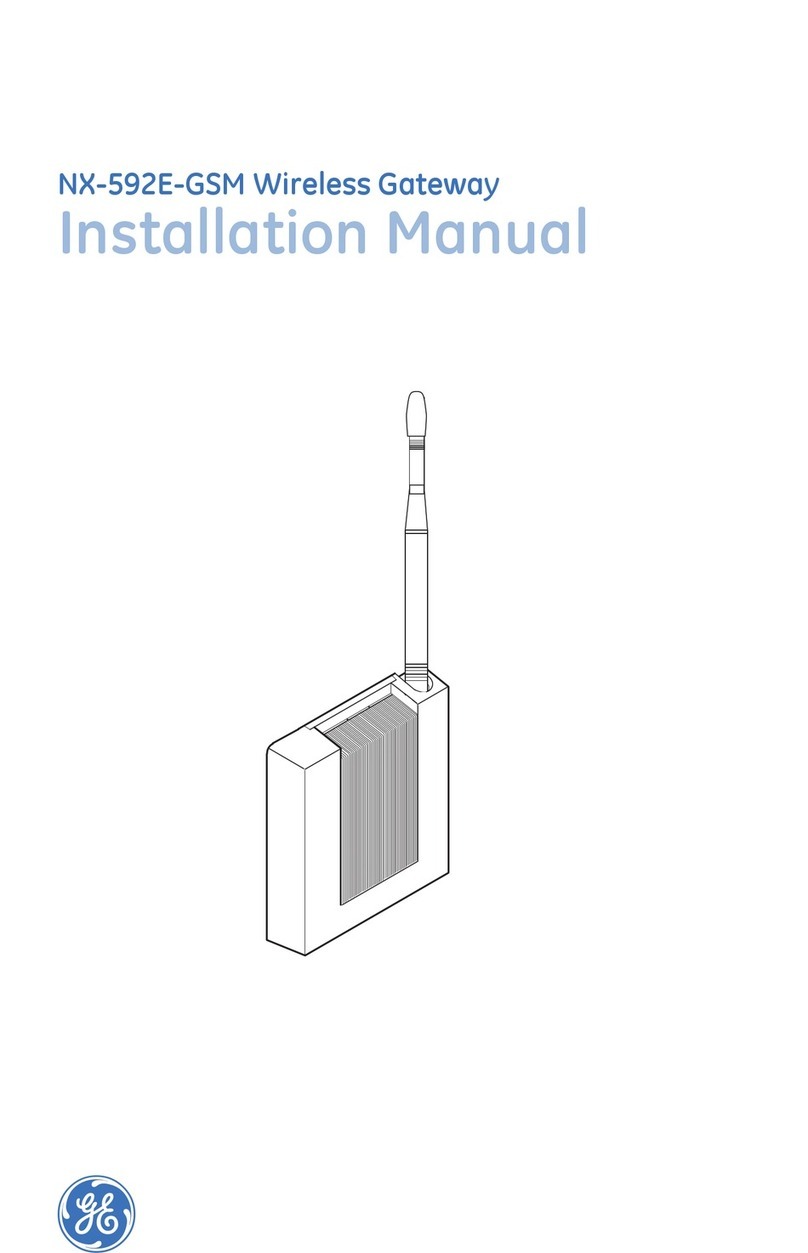
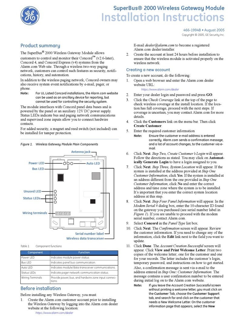
GE Security NX-592E User manual

NX-592E Wireless Gateway
Installation Instructions

Copyright Copyright © 2005, GE Security Inc. All rights reserved.
This document may not be copied in whole or in part, or otherwise reproduced except as
specifically permitted under US copyright law, without the prior written consent from GE.
Document number/revision: 466-2204B.
Disclaimer The information in this document is subject to change without notice. GE, in keeping pace with
technological advances, is a company of product innovation. Therefore, it is difficult to ensure
that all information provided is entirely accurate and up-to-date. GE accepts no responsibility
for inaccuracies or omissions and specifically disclaims any liabilities, losses, or risks, personal
or otherwise, incurred as a consequence, directly or indirectly, of the use or application of any
of the contents of this document.
This publication may contain examples of screen captures and reports used in daily operations.
Examples may include fictitious names of individuals and companies. Any similarity to names
and addresses of actual businesses or persons is entirely coincidental.
Trademarks and patents GE and the GE monogram are registered trademarks of General Electric.
Other trade names used in this document may be trademarks or registered trademarks of the
manufacturers or vendors of the respective products.
Software license agreement GE software supplied with GE products is proprietary and furnished under license and can be
used or copied only in accordance with the license terms.
THE ENCLOSED PROGRAM IS FURNISHED SUBJECT TO THE TERMS AND CONDITIONS OF THIS
AGREEMENT. RETENTION OF THE PROGRAM FOR MORE THAN 30 DAYS, OPENING OF THE SEALED
WRAPPER, IF ANY, SURROUNDING THE PROGRAM, OR USE OF THE PROGRAM IN ANY MANNER
WILL BE CONSIDERED ACCEPTANCE OF THE AGREEMENT TERMS. IF THESE TERMS ARE NOT
ACCEPTABLE, RETURN THE UNUSED PROGRAM AND ANY ACCOMPANYING DOCUMENTATION TO
GE FOR A FULL REFUND OF THE LICENSE FEE PAID. (FOR INFORMATION REGARDING THE RETURN
OF PROGRAMS ENCODED OR INCORPORATED WITHIN EQUIPMENT, CONTACT THE NEAREST GE
SALES OFFICE.)
Intended use Use this product only for the purpose for which it was designed; refer to the data sheet and user
documentation. For the latest product information, contact your GE sales representative or visit
us online at www.gesecurity.com.
FCC compliance This equipment has been tested and found to comply with the limits for a Class B digital device,
pursuant to part 15 of the FCC Rules. These limits are designed to provide reasonable protection
against harmful interference when the equipment is operated in a commercial environment.
This equipment generates, uses, and can radiate radio frequency energy and, if not installed
and used in accordance with the instruction manual, may cause harmful interference to radio
communications.
You are cautioned that any changes or modifications not expressly approved by the party
responsible for compliance could void the user's authority to operate the equipment.
Contact Direct all inquiries about GE’s legal policies with regard to this product to:
Director of Legal Services
GE Security
12345 SW Leveton Drive
Tualatin, OR 97062-9938 USA

1
Preface
This is the GE NX-592E Installation Manual for models NX-592E-S, NX-592E-W, and NX-592E-BO. This
document includes an overview of the product and detailed instructions explaining:
• how to install the unit; and
• how to program the unit.
There is also information describing how to contact technical support if you have questions or concerns.
To use this document effectively, you should have the following minimum qualifications:
• a basic knowledge of NetworX panels; and
• a basic knowledge of electrical wiring and low-voltage electrical connections.
Read these instructions and all ancillary documentation entirely before installing or operating this product. The
most current versions of this and related documentation may be found on our website. Refer to Online
publication library on page 13 for instructions on accessing our online publication library.
Note: A qualified service person, complying with all applicable codes, should perform all required hardware installation.
Conventions used in this document
The following conventions are used in this document:
Safety terms and symbols
These terms may appear in this manual:
Bold Menu items and buttons.
Italic Emphasis of an instruction or point; special terms.
File names, path names, windows, panes, tabs, fields, variables, and other GUI elements.
Titles of books and various documents.
Blue italic (Electronic version.) Hyperlinks to cross-references, related topics, and URL addresses.
Monospace Text that displays on the computer screen.
Programming or coding sequences.
CAUTION: Cautions identify conditions or practices that may result in damage to the equipment or other property.
WARNING: Warnings identify conditions or practices that could result in equipment damage or serious personal injury.

NX-592E
Installation Manual
2
Product summary
The NX-592E Wireless Gateway allows NetworX owners to control and monitor their system status from the
Alarm.com website. Through a wireless, two-way paging network, your customer has limited controls on such
features as security, notifications, history, and authentication (see System operation from Alarm.com on
page 17 for further details). The modem for the NX-592E-BO must be purchased separately from Alarm.com.
Figure 1. NX-592E-S, NX-592E-W, NX-592E-BO
Utilizing the wireless paging network, NetworX owners may also be notified of system events by e-mail,
pager, or phone.
The wireless module interfaces with the NetworX panel data bus and is powered by the panel or an auxiliary 12
VDC power supply. Status LEDs indicate bus and paging network communications. See Figure 2 on page 3
for an illustration of the main module components, and see Table 1 on page 3 for a description of each
component..
NX-592E-S
NX-592E-BO
NX-592E-W

3
Figure 2. Main module components
Table 1. Module component descriptions
Component Function
Bus LED Indicates data bus activity between panel and module
Status LEDs Indicate communications status with two-way pager network
Wiring terminals Provides panel wiring connections
Antenna jack Antenna connection for wireless data transceiver
Bus LED
Status LEDs
Antenna jack
Wireless data transceiver
Serial number label
Wiring terminals

NX-592E
Installation Manual
4
Before installation
Before installing any Wireless Gateway, you must:
1. Create the Alarm.com customer account prior to installing the Wireless Gateway by logging into the
Alarm.com dealer website at the following location:
https://www.alarm.com/dealer
2. Create the account at least 24 hours before installation to ensure that the wireless module is activated
properly on the wireless network.
Creating a new account
To create a new account, do the following:
1. Open a web browser and enter the Alarm.com dealer website URL:
https://www.alarm.com/dealer
2. Enter your dealer login and password and press GO.
3. Go to the Coverage/FAQ page to check wireless coverage at the install location. If the location has full
coverage, proceed with the next steps. If coverage is uncertain, you may contact Alarm.com for more
details.
4. Click the Customers link on the menu bar. Then click Create Customer.
5. Enter the required customer information
Note: Ensure the customer e-mail address is entered correctly. Alarm.com sends a confirmation message, and a list
of account changes, to the customer via e-mail.
6. Click Next. Step Two, Create Customer’s Login will appear. Follow the directions as stated. You may
click on Automatically Generate Login to have a login assigned to you.
7. Click Next. Step Three, System Location will appear. If the system is installed at the address provided
at Step One Customer Information, click Ye s . If the system is installed at an address different from the
one provided in Step One Customer Information, click No and enter the correct address and time zone
where the system is to be installed. It’s important that you enter the correct system location address at
this step.
8. Click Next. Step Four Panel Information will appear. In the Modem Serial # dialog box, enter the
10-character ID found on the gateway you purchased. If you are unable to proceed with the modem
serial number, contact Alarm.com.
9. Select NX in the Panel Type list box.
CAUTION: The website will issue a warning about the number of zones attached to the panel. Unlike Concord and
Simon, the Alarm.com gateway cannot learn the number of zones from the panel. By default, the gateway
will assume that eight zones are installed. If the number of zones is different, you will have to send a
command to the panel later via the Customer Support page of the Dealer website. See the last paragraph of
this section for more details.

5
10. Click Next. The Confirmation screen will appear. Review the customer information. If you need to
change any of the information, click the Edit link next to the field you want to update.
11. Click Done. The Account Creation Successful screen will appear. Click View and Print Welcome
Letter. Print two copies of the welcome letter; one for the customer and one for your records. The
letter includes the customer’s login, temporary password, and instructions on how to get started.
Also, a confirmation message is sent via e-mail to the address entered in Step One: Customer
Information. The message contains a user confirmation number to be entered during initial log on to
the Alarm.com website.
Note: If you leave the Account Creation Successful screen without printing a welcome letter, you must click on the
Customer Tab, choose the Customer Support tab, and search for and click on the customer that needs a New
Welcome Letter. On the customer information page that appears, select the New Welcome Letter tab in the
Customer Support Option panel on the left-hand side.
If the customer does not receive the confirmation e-mail, you may send a new confirmation e-mail by
selecting Resend Confirmation Number in the Customer Support Options panel.
Programming the number of zones into the gateway
This section describes how to program the number of zones into the gateway.
Once the account is created, log on to the Alarm.com Dealer website at:
https://www.alarm.com/dealer
Click on the Customers Tab, and then click on the Customer Support subtab. Enter the name of the account
in the Customer Search field and click on Submit Search. Then click on the customer name in the Search
Results list below the Customer Search area. When the account information appears, click on the Sensor List
link on the left side of the page under Customer Support Options. Enter the number of installed zones for the
customer’s NX panel and click Submit.
Note: If the panel was not powered up after the account was created, no zone list will appear on this page. The command to
set the number of zones will be sent to the panel right away if the panel is powered up, or later when the panel powers
up if it has not already powered up.
CAUTION: Unlike Concord and Simon, the Alarm.com gateway cannot learn the number of zones from the NX panel.
By default, the gateway will assume that eight zones are installed. If the numbers of zones is different, you
will have to send a command to the panel via the Customer Support page of the Alarm.com Dealer website.

NX-592E
Installation Manual
6
Installation
Installation requires you to position the module, connect all wires and mounts, and optionally install a case
tamper.
Installation guidelines
Use the following guidelines when installing the module:
• NetworX panels support a maximum of one Wireless Gateway per system.
• Use four-conductor, 22- or 18-gauge stranded wire to connect the module to the panel (see Table 2).
• Mount the module as close to the panel as possible. The module draws a maximum of 65 mA
(continuous) and up to 1600 mA (instantaneous peaks) from the panel.
• Do not exceed the panel’s total output power when using panel power for bus devices and hardwired
sensors (refer to specific panel installation instructions).
Tools and supplies needed
• Slotted and Phillips screwdrivers
• Drill (3/8” drive) and drill bits
• Wire-cutter/stripper
• Four-conductor, 22-gauge or larger stranded wire
• Modem (sold separately on NX-592E-BO)
• Modem antenna and mounting screws (included)
• #6 panhead screws and wall anchors (four each included)
Locating the module
Use the following guidelines when locating the module:
• Locate the module near an outside wall, preferably on an upper level.
• Leave 12 to 18 inches of space near the module antenna jack.
• Avoid locating the module in areas with excessive metal or electrical wiring, such as a furnace or
utility room.
• Make sure the antenna is pointing up.
Table 2. Maximum wire length
Gauge Max. wire length to panel
22 ga. 40 feet
18 ga. 90 feet

7
Mounting
To mount the module, do the following:
1. Remove the module’s enclosure cover.
Figure 3. Removing the enclosure/mounting hole locations
Note: If you are using the NX-592E-S or NX-592E-W, proceed to step 4. Steps 2 and 3 are for NX-592E-BO and a
modem purchased separately.
2. Remove the existing screws from the modem mount located on the backplate.
3. Place the modem over the spacers located on the mounts and secure the modem with the screws (see
Figure 3).
4. Fasten the antenna to the antenna jack (see Figure 2 on page 3).
5. Place the module backplate at the desired location; ensure it is level and mark the three mounting holes
and the wire access area (see Figure 3). Be sure to leave at least 12 to 18 inches above the backplate
for the antenna.
6. Drill holes at mounting hole and wire access area locations.
7. Install wall anchors and secure the module backplate to the wall with #6 panhead screws.
You must be free of static electricity before handling circuit boards. Wear a grounding strap or touch a bare grounded
metal surface to discharge static electricity.
Press down here and
pull away from base
Mounting hole
Mounting hole
Mounting hole
Wire access area

NX-592E
Installation Manual
8
Wiring connections
1. Remove panel AC power and disconnect the backup battery.
2. Wire the module to the panel bus and power terminals (see Figure 4 on page 8 and Table 3 on page 8).
Figure 4. Wiring connections for the Wireless Gateway
To prevent damage to the panel or module, you must remove panel AC power and disconnect the backup battery prior to
changing any wire connections.
Table 3. Terminal descriptions
Terminal descriptions
POS Connect to the KP POS terminal of the NetworX panel
COM Connect to the KP COM terminal of the NetworX panel
DATA Connect to the KP DATA terminal of the NetworX panel
KP POS KP COM KP DATA
POS COM DATA
Panel
Gateway

9
Installing a case tamper switch
If your module is easily accessible, you may consider adding a case tamper detection switch. This switch
activates an alarm or trouble signal (depending on panel programming) when the module cover is removed.
1. Slide the reed switch into the plastic holder on the module backplate (see Figure 5).
Figure 5. Installing a case tamper switch
2. Connect a reed switch (with EOL resistor) to any unused hardwire input on the panel. For the EOL
resistor value, see the control panel installation manual.
3. Press the magnet into the tabs located on the module cover. Next, press the magnet clip over the
magnet until the clip locks into place (see Figure 5).
Module backplate
Module cover
To zone input
EOL resistor
Magnet clip
Magnet

NX-592E
Installation Manual
10
Power up
This section describes how to deliver power to both the module and panel and how to establish a
communication link between the two.
1. Verify that all wiring between the panel and module are correct.
2. Reconnect the backup battery and restore panel AC power.
Enrolling the module
The NetworX control panels have the ability to automatically find and store in memory the presence of all
keypads, zone expanders, wireless receivers, output modules, and any other device on the keypad bus. This
allows these devices to be supervised by the control panel. To enroll the devices, enter Program Mode using
the procedure outlined in the control panel installation manual. When you exit Program Mode, the control
panel will automatically enroll the devices. The enrolling process takes about 12 seconds, during which time
the “Service” LED will illuminate. User codes will not be accepted during the enrolling process. Once a
module is enrolled, if it is not detected by the control, the “Service” LED will illuminate. When initially
powering up, the control panel automatically performs the device enrollment process.
Programming using the keypad
The wireless gateway needs to know the address of at least one of the LCD keypads. Some commands, such as
getting the zone names for display on the website, will not work if the keypad address is not known. By
default, the wireless gateway assumes a keypad address of 192 (keypad 1, partition 1). If your LCD keypad is
programmed differently (press *94 + installer code to check), you must change the wireless gateway keypad
address. To change the gateway keypad address, do the following:
1. Press *, then 8.
2. Enter the “Go to program” code. The default code is 9, 7, 1, 3. If the code is valid, the keypad display
will prompt you for a device address.
3. Enter the address of the NX-592E, which is 7, 8, then press #. At this point, the keypad display will
prompt you for a programming location to be entered.
4. Enter 0, followed by the #key. Location 0, which is the LCD address will display. The default is 192.
For a list of addresses, see Table 4 on page 11.
5. To change the LCD keypad address, enter the new address, followed by the *. The display will return
to the location prompt.
6. To exit this location without changing the data, press the #key.
7. To review the data, repeat the above procedure, pressing the *key without entering data first. If you
attempt to program an invalid entry for a particular segment, the keypad sounder will emit a triple error
beep (beep, beep, beep) and remain in that segment awaiting a valid entry.
8. To exit Program Mode, press the Exit key to exit this programming level. Pressing the Exit key again
will exit the Program Mode.

11
While in programming mode and not in a location, the number in parentheses is the location you were
previously changing. For example, if the display reads “Enter location, then # (2)”, it is reminding you that
location 2 was the last location you programmed.
Location 0 programming the LCD keypad address
Certain commands in the NX-592E require it to know the location of at least 1 LCD keypad (if one exists in the
system). If your system has an LCD keypad we recommend that you place in partition 1 keypad 1. This will
allow location 0 to be left at the factory default. If the LCD keypad is selected as something other than partition
1 keypad 1, program the appropriate address in location 0. Select the address from the following chart.
Status LEDs
The status LEDs indicate the module’s current signal and status. The bottom red REG LED indicates the
module is registered and in range. The yellow ACK and green XMT LEDs indicate the module’s message
status. The top red ERR LED indicates proper communication between the main board of the NX-592E and the
wireless modem. See Table 5 on page 12 for a complete list of LED condition patterns.
The red REG LED remains:
• On - when the module is registered and in range.
• Off - when the module is out of range and not registered with the network.
• Flashing - when the module is registered but out of range.
The yellow ACK LED remains:
• On - after the first message has been sent to and received by Alarm.com services.
• Off - until a message has been sent by the module.
• Flashing - while the first message is being sent by the module.
Table 4. Addresses
Keypad Part 1 Part 2 Part 3 Part 4 Part 5 Part 6 Part 7 Part 8
1 192 193 194 195 196 197 198 199
2 200 201 202 203 204 205 206 207
3 208 209 210 211 212 213 214 215
4 216 217 218 219 220 221 222 223
5 224 225 226 227 228 229 230 231
6 232 233 234 235 236 237 238 239
7 240 241 242 243 244 245 246 247
8 248 249 250 251 252 253 254 255

NX-592E
Installation Manual
12
The green XMT LED remains:
• Off - immediately after Alarm.com services has received a message.
• Flashing - while a message is being sent by the module.
The red ERR LED remains:
• Off - If there is no communication between the main board of the NX-592E and the wireless modem
board.
• Flashing - with each message exchanged between the main board of the NX-592E and the wireless
modem board.
Table 5. LED condition patterns
Condition
Number Red REG LED Yellow ACK LED Green XMT LED Condition
1 Off Off Off Module not powered/not working
2 On Off Off Module in range, first message not sent, not
currently sending message
3 On On Off Module in range, first message sent, not
current sending message
4 On On Flashes Module in range, first message sent,
currently sending message

13
Troubleshooting and support
This section provides information to help you diagnose and solve various problems that may arise while
configuring or using your GE Security product and offers technical support contacts in case you need
assistance.
Troubleshooting
If the bus LED is not flashing, turn off panel AC power and verify that all wiring is correct.
Note: All buffered messages may be received from the two-way paging network upon restoring power to the module.
If the module status LEDs do not immediately turn on after initial power-up, you may have to wait five to eight
minutes for the module to communicate with Alarm.com services.
If touchpads/sirens are beeping even though the system is not armed, press *, 2 to display the trouble condition.
Refer to specific touchpad manual for details.
Contacting technical support
For assistance installing, operating, maintaining, and troubleshooting this product, refer to this document and
any other documentation provided. If you still have questions, you may contact technical support during
normal business hours (Monday through Friday, excluding holidays, between 6 a.m. and 5 p.m. Pacific Time).
Note: Be ready at the equipment before calling for technical support.
Online publication library
Another great resource for assistance with your GE Security products is our online publication library,
available to all of our customers on our website. To access our publication library, go to our website at the
following location:
http://www.gesecurity.com
In the Tools area at the top, click the Publication Library link. After you register and log on, you may search
through our online library for the documentation you need.1
Table 6. Sales and support contact information
Sales Technical support
Phone: Toll-free: 888.GESECURity (888.437.3287 in the US, including Alaska and Hawaii; Puerto Rico; Canada).
Outside the toll-free area: 503.885.5700.
E-mail [email protected] generaltec[email protected]
Fax 800.483.2495 541.752.9096 (available 24 hours a day)
1. Many GE Security documents are provided as PDFs (portable document format). To read these documents, you will need
Adobe Acrobat Reader, which can be downloaded free from Adobe’s website at www.adobe.com.

NX-592E
Installation Manual
14
Appendix A Creating a new subscriber account
This section describes how to create a new subscriber account on the Alarm.com website. Be sure to discuss
this section with your customer prior to the module’s final installation.
After you have created a new subscriber account and installed the module, instruct your customer to log on to
the Alarm.com website. You will need the following items to complete the new subscriber setup procedure:
• Login and temporary password included on the Alarm.com Welcome Letter.
• Confirmation number sent from Alarm.com to your customer’s e-mail.
• Complete list of system sensors and touchpads.
• A phone number and e-mail address for Alarm.com to send notifications to.
After you have gathered the required information, log on to the following address:
https://www.alarm.com
Log on by entering the correct login name and temporary password. A New Subscriber Setup Wizard appears.
Assist the customer in creating an address book and turning on all Alarm.com notifications.

15
Appendix B Information for the user
Leave Customer information on page 17 from this document with your customer. The information on these
pages describes security system use and limitations of the Alarm.com website. This information does not
appear in any owner’s manual or user guide.

NX-592E
Installation Manual
16
Appendix C Specifications
Table 7. Specifications
Specification Rating
Compatibility NetworX panels.
Power requirements 9.5 to 15 VDC, 12 V nominal, 65 mA (continuous), 1600 mA (instantaneous
peak) maximum from panel or auxiliary power supply.
Paging network One wireless, two-way paging transceiver (ReFLEX 25 for NX-592E-W or
ReFLEX 50 for NX-592E-S).
Power/data bus One three-wire NetworX power/communications data bus.
Indicators One module/panel communication status LED. Four wireless
communication status LEDs.
Operating temperature 32° to 120°F (0° to 49°C).
Storage temperature -30° to 140°F (-34° to 60°C).
Humidity 90% relative humidity; non-condensing.
Case color Belgian gray.
Case materials High impact, ABS plastic.
Dimensions 5.25 x 4.125 x 1 in. (H x W x D).
Installation Wall mount.

17
Appendix D Customer information
System operation from Alarm.com
Operating your system from the Alarm.com website gives you limited controls for managing your customer
account, viewing system status and history, arming your system, and other functions through an easy to use
web interface. Web-enabled features depend on selected service packages and may vary.
For the most current descriptions of available operations, see the Alarm.com website and click on the help tab
in the category you have questions about.
Notices
FCC part 15 information to the user.
This device complies with parts 15 of the FCC rules. Operation is subject to the following two conditions:
1. This device may not cause harmful interference.
2. This device must accept any interference received, including interference that may cause undesired
operation.
Changes or modifications not expressly approved by GE Security can void the user’s authority to operate the
equipment.
The wireless modem used with this product is an intentional radiator. Refer to labeling on the modem for the
FCC ID.

NX-592E
Installation Manual
18
Table of contents
Other GE Security Gateway manuals