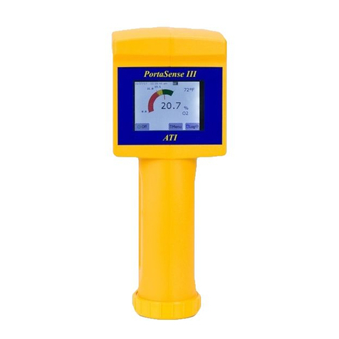
Analytical Technology PortaSens II User manual

PortaSensII
Gas Leak Detector
HomeOffice EuropeanOffice
AnalyticalTechnology, Inc.ATI (UK)Limited
6Iron Bridge DriveUnit 1&2GateheadBusiness Park
Collegeville,PA 19426 Delph NewRoad, Delph
SaddleworthOL3 5DE
Ph: (800)959-0299 Ph: 0800-018-4020
(610)917-0991 +44 (0)1457-873-318
Fax: (610)917-0992 Fax: +44 (0)1457-874-468
Email: sales@analyticaltechnology.com Email: sales@atiuk.com

PRODUCT WARRANTY
AnalyticalTechnology, Inc.(Manufacturer)warrantstothe Customerthat
if anypart(s)of the Manufacturer'sproductsprovestobedefectiveinmaterialsor
workmanshipwithintheearlierof 18monthsof the dateof shipment or12
monthsof the dateof start-up, suchdefectivepartswillbe repaired orreplaced
free of charge. Inspection andrepairstoproductsthought tobedefectivewithin
the warrantyperiod willbe completed at the Manufacturer'sfacilitiesin
Collegeville,PA. Productsonwhichwarrantyrepairsarerequired shallbe
shipped freight prepaidtotheManufacturer. The product(s)willbe returned
freight prepaidand allowed ifitisdetermined bythe manufacturerthat the part(s)
faileddue todefectivematerialsorworkmanship.
Thiswarrantydoesnot coverconsumableitems, batteries, orwearitems
subject toperiodicreplacement including lampsand fuses.
Gassensors,except oxygen sensors,arecovered bythiswarranty, but
aresubject toinspection forevidenceof extended exposuretoexcessivegas
concentrations. Shouldinspectionindicatethat sensorshavebeen expended
ratherthan failed prematurely, the warrantyshallnot apply.
The Manufacturerassumesno liabilityforconsequentialdamagesof any
kind,and the buyerbyacceptanceof thisequipmentwillassumeallliabilityfor
the consequencesofitsuseormisusebytheCustomer, hisemployees, or
others. Adefect withinthe meaning of thiswarrantyisanypart of anypieceof a
Manufacturer'sproduct whichshall, when suchpartiscapableof being renewed,
repaired, orreplaced, operatetocondemnsuchpieceofequipment.
Thiswarrantyisinlieuof allotherwarranties(includingwithoutlimiting the
generalityof the foregoing warrantiesof merchantabilityandfitness fora
particularpurpose),guarantees,obligationsorliabilitiesexpressedorimplied by
the Manufactureroritsrepresentativesand bystatuteorruleoflaw.
Thiswarrantyisvoidifthe Manufacturer'sproduct(s)hasbeensubject to
misuseorabuse,orhasnot been operated orstored inaccordancewith
instructionsorif theserialnumberhasbeen removed.
AnalyticalTechnology, Inc. makesno otherwarrantyexpressed orimplied
except asstated above.

PortaSensII GasDetector C16 Leak Detector
O&MManual
Rev. G,11/07 -2-
TABLE OFCONTENTS
SPECIFICATIONS.................................................................................................................................................3
INTRODUCTION...................................................................................................................................................4
UNPACKING.........................................................................................................................................................6
FIGURE 1–FRONTPANELOVERVIEW(ATI-0401)......................................................................................6
OPERATION..........................................................................................................................................................7
SENSOR /CHARGE LED..........................................................................................................................................7
FIGURE 2-MAINDETECTORDISPLAY.......................................................................................................7
RESPONSETEST................................................................................................................................................8
SAMPLE INLET OPTIONS.................................................................................................................................9
DISPLAY RESOLUTION....................................................................................................................................9
RESPONSETIME...............................................................................................................................................10
INTERFERENCES..............................................................................................................................................11
GAS CONCENTRATION ALARM FUNCTIONS...............................................................................................13
PUMPTROUBLE ALARM.................................................................................................................................13
BATTERYPOWER SUPPLY..............................................................................................................................14
RS-232 COMPUTERINTERFACE.....................................................................................................................14
FIGURE 3–CHARGERJACK/ COMMPORTORIENTATION(ATI-0402).....................................................15
START-UPSEQUENCE.......................................................................................................................................16
OPERATING MODES........................................................................................................................................17
SENSORMODULE EXCHANGE........................................................................................................................18
FIGURE 4–MANIFOLDASSEMBLYEXPLODEDVIEW(ATI-0403)............................................................19
PROGRAMMING.................................................................................................................................................20
ADJUSTING ALARM SETPOINTS....................................................................................................................21
SETTING DISPLAY VARIABLES.....................................................................................................................22
SETTING SAMPLE MODE VARIABLES...........................................................................................................24
CALIBRATION.....................................................................................................................................................25
ZEROADJUSTMENT........................................................................................................................................25
FIGURE 5-CALIBRATIONFLOWSCHEMATIC...........................................................................................26
DATALOGGING..................................................................................................................................................27
DATALOGGER SOFTWARE.............................................................................................................................28
INSTALLING SOFTWARE.........................................................................................................................................28
LOGGING PERIODS ................................................................................................................................................28
STARTINGTHE DATALOG PROGRAM.......................................................................................................................29
FIGURE 6-CONFIGURE TABINDATALOG SOFTWARE............................................................................29
FIGURE 7-DOWNLOADTABINDATALOGSOFTWARE.............................................................................31
DISPLAYAND GRAPHOF DATA ..............................................................................................................................31
MAINTENANCE...................................................................................................................................................32
TROUBLESHOOTING.........................................................................................................................................33
TROUBLESHOOTING(CONT’D)........................................................................................................................34
SPAREPARTSLIST.............................................................................................................................................35

PortaSensII GasDetector C16 Leak Detector
O&MManual
Rev. G,11/07 -3-
SPECIFICATIONS
Range: Dependent on sensormoduleused
Display: Back-litgraphicsliquidcrystaldisplay
Accuracy: Sensordependent but generally±5%ofvalue (limited bycal. gas)
Sensitivity: 1% of sensormodulerange
Repeatability:±1% ofsensormodulerange
Outputs: RS-232 output ofstored gasvalues
0-1VDC analog (requiresoptional output cable)
Memory: 12,000 datapoints
StorageInterval:Programmablefor1,5, 10,and 15 minuteintervals
TypicalCapacity: 8Daysat 1minutestorage interval.
Alarms: Three concentration alarmswithadjustablesetpoints.
Alarmsmaybe setforhigh,low, oroff.
Lowflowand lowbattery alarms
Alarmsdisplayed on LCD and indicated byaudiblebeeper
Power:Dcellbattery,alkaline recommended, 75hoursoperation
Internalrechargeablebatteryforbackup power, 6hoursoperation
115 or220 VACchargersavailable
Operating Temp.: -25º to+55º C
Humidity: 0-95% Non-condensing
DetectorMaterial: Glass filled nylon, PVC, and stainless steel
Accessories: 10”Sampling wand, Teflon lined
Battery charger
Three sparefilters&OutletTube Barbed Fitting
Flowmeter
RS-232 Outputcable(DB9connector)
DataLog PCsoftwareon CD ROM
Storage case
Calibration “T”
Shipping Weight: 3lbs. (1.4Kg.)

PortaSensII GasDetector C16 Leak Detector
O&MManual
Rev. G,11/07 -4-
INTRODUCTION
The SeriesC16 PortaSensII isaportable,batteryoperated instrumentdesigned to
measureavarietyofgasesinambientair.WhileC16 detectorscan onlymeasureonegasata
time,the unitusesinterchangeablesmartsensorssothatitcan be quicklyconverted tomeasure
anothergas.The tablebelowshowsthe currentlyavailablesensormodulesand the
measurementrangesthat can be covered byeachmodule. Notethatthe C16 detectorrange can
be adjusted bythe userforanyfullscalerange betweenthe minimumrange and maximumrange
indicated foreachmodule.Forexample,withan ammoniamodule#00-1010 inserted intothe
unit,the range can be set at anywherebetween 0-50 PPM and 0-500 PPM.
OXIDANTGASES
GAS SENSORNO. MIN. RANGE MAX. RANGE RESOLUTION
Bromine 00-1000 0-1PPM 0-5PPM 0.01 PPM
00-1001 0-5PPM 0-100 PPM 0.1PPM
Chlorine 00-1002 0-1PPM 0-5PPM 0.01 PPM
00-1003 0-5PPM 0-100 PPM 0.1PPM
Chlorine Dioxide 00-1004 0-1PPM 0-5PPM 0.01 PPM
00-1005 0-5PPM 0-100 PPM 0.1PPM
Fluorine 00-1006 0-1PPM 0-5PPM 0.01 PPM
00-1007 0-5PPM 0-100 PPM 0.1PPM
Hydrogen Peroxide 00-1042 0-10 PPM 0-100 PPM 0.1PPM
Iodine 00-1036 0-1PPM 0-5PPM 0.01 PPM
00-1037 0-5PPM 0-100 PPM 0.1PPM
Ozone 00-1008 0-1PPM 0-5PPM 0.01 PPM
00-1009 0-5PPM 0-100 PPM 0.1PPM
GENERALGASES
Ammonia 00-1010 0-50 PPM 0-500 PPM 1PPM
00-1011 0-500 PPM 0-2000 PPM 1PPM
Carbon Monoxide 00-1012 0-50 PPM 0-1000 PPM 1PPM
Hydrogen 00-1041 0-500 PPM 0-2000 PPM 1PPM
00-1013 0-1% 0-10% 0.01%
Oxygen 00-1014 0-5% 0-25% 0.1%
NitricOxide 00-1021 0-50 PPM 0-500 PPM 1PPM
Phosgene 00-1015 0-1PPM 0-5PPM 0.01 PPM
00-1016 0-5PPM 0-100 PPM 0.1PPM
ACIDGASES
Hydrogen Chloride 00-1017 0-10 PPM 0-200 PPM 0.1PPM
Hydrogen Cyanide 00-1018 0-10 PPM 0-200 PPM 0.1PPM
Hydrogen Fluoride 00-1019 0-10 PPM 0-200 PPM 0.1PPM
Hydrogen Sulfide 00-1020 0-10 PPM 0-200 PPM 0.1PPM
Nitrogen Dioxide 00-1022 0-10 PPM 0-200 PPM 0.1PPM
SulfurDioxide 00-1023 0-10 PPM 0-500 PPM 0.1PPM
AcidGases 00-1038 0-10 PPM 0-200 PPM 0.1PPM
(List continueson nextpage)

PortaSensII GasDetector C16 Leak Detector
O&MManual
Rev. G,11/07 -5-
HYDRIDEGASES
Arsine 00-1024 0-500 PPB 0-2000 PPB 1PPB
00-1025 0-10 PPM 0-200 PPM 0.1PPM
Diborane 00-1026 0-500 PPB 0-2000 PPB 1PPB
00-1027 0-10 PPM 0-200 PPM 0.1PPM
Germane 00-1028 0-500 PPB 0-2000 PPB 1PPB
00-1029 0-10 PPM 0-200 PPM 0.1PPM
Hydrogen Selenide 00-1030 0-500 PPB 0-2000 PPB 1PPB
00-1031 0-10 PPM 0-200 PPM 0.1PPM
Phosphine 00-1032 0-500 PPB 0-2000 PPB 1PPB
00-1033 0-10 PPM 0-200 PPM 0.1PPM
00-1034 0-200 PPM 0-2000 PPM 1PPM
Silane 00-1035 0-10 PPM 0-200 PPM 0.1PPM
HYDROCARBONGASES
Ethylene Oxide 00-1039 0-20 PPM 0-200 PPM 0.1PPM
Formaldehyde 00-1040 0-20 PPM 0-200 PPM 0.1PPM
Alcohol 00-1043 0-50 PPM 0-500 PPM 1PPM
00-0144 0-500 PPM 0-2000 PPM 1PPM
Acetylene 00-1057 0-50 PPM 0-500 PPM 1PPM
EachSeriesC16 isacompletebattery-operated measuring instrumentcontaining a
samplepumptodrawairintothe sensormanifold.Agraphicsliquidcrystaldisplaywithback-light
providesgasconcentration displayand alarmindication.The basicinstrumentissoldwithouta
sensormodule.Sensormodulesmustbe ordered separately.Everyunitcomeswithasensor
keeperinwhichthe sensormodulewill be shipped.The SensorKeeperwill holdup to(4)
sensors.If morethan (4)sensorsareordered,ATIrecommendsthatyou purchasean additional
sensorkeepertokeep sensorson biasuntilreadyforuse.The unitispackaged inapadded
plasticcarrying casecontainingallaccessories.

PortaSensII GasDetector C16 Leak Detector
O&MManual
Rev. G,11/07 -6-
UNPACKING
When you receiveyourC16 PortableGasDetector,open the carrying caseand inspect
the contentstobe surethatno shipping damage hasoccurred.The following itemsshouldbe
included inside the case:
1-SeriesC16 PortaSensII GasDetector(without sensormodule)
1-Battery Charger
1-SamplingWand
1 -Flowmeter
3-Replacement filters
1-Spare“D”cell battery
1-OutletTube Barbed Fitting
1 -RS-232 Cable
1 -DataLog PCsoftwareCD ROM
1–Calibration “T”
1–SensorKeeper(containing (1)ormoresensormodules)
Inaddition tothe standarditemslisted above,anyadditionalsensormodulesthatwere
ordered withthe unitwillbe packed inside the carryingcase(unlessspacedoesnotallowdue to
the quantityordered).
FIGURE1–FRONT PANELOVERVIEW(ATI-0401)

PortaSensII GasDetector C16 Leak Detector
O&MManual
Rev. G,11/07 -7-
OPERATION
Sensor/ ChargeLED
The C16 isequipped withasensor/ charge LEDtogivethe useravisualindication that
the sensorisreadyforimmediateuse. ThisLEDwillflashabout every3seconds. The sensor
LEDwillflasheven when the batteriesinthe C16 aretoo lowtorun the instrument.Ifthe
instrument will not start,replacethe D-Celland rechargethe secondary battery.Ifthe sensor/
charge LEDisnotflashing the sensorhaslost BIAS andmayrequireseveral hourstostabilize.
Replacethe D-Celland recharge the secondary battery.
The C16 LeakDetectorisshipped readytousedirectlyout ofthe box.No adjustmentsof
anykind arenecessary.Simplyremovethe instrumentfromthe storage caseand pressand
releasethe green button belowthe display.Theaudiblehornwillbeep onceand the internal
pumpwillbegintopull sampleintothe flowmanifold.
CAUTION:Fortheinstrumenttowork properly,theINLETandOUTLETportsonthe
back oftheinstrumentmustnotbeblockedorobstructed.
When powerisfirstapplied,the LCD displaywill scroll through anumberofdifferent
start-up displays.The meaning ofthesedisplayswill be explained inlatersectionsofthis
manual.However,thesedisplayswill notaffectthe useofthe instrumentinmaking gas
measurementsassoon aspoweristurned on.Letthestart-up displayscyclethrough untilthe
displaystopsat the maindisplay(orpress the SKIPkey). The unit willindicategasconcentration
inlarge numbers,withthe gassymboland unitsof measuretothe rightof the number.Figure2
showshowthe maindisplaywilllookinitially.
P0 PPM
NH3
OFF MENUSMPL
FIGURE2-MAINDETECTORDISPLAY
Tousethe detectorimmediately,removethe samplingwandfromthe carrying caseand
plug it intothe mating connectoron the back ofthe flow manifold.The internalsamplepumpwill
drawgassamplesthrough the wand and displaythe concentration on the LCD.No adjustments
areneeded.However,you shouldrun aresponsetestasdescribed on the nextpage,priorto
using the instrument.
When you havefinished using the detector,press andholdthe green switch(marked Off
on the LCD)until the LCD indicatesthe message “POWERDOWN”.Releasethe switchand the
unit willshut off.

PortaSensII GasDetector C16 Leak Detector
O&MManual
Rev. G,11/07 -8-
RESPONSETEST
Priortousing the detectorforfieldmeasurements, itisrecommended that the unitfirst be
tested forgasresponse.Aresponsetestsimplymeansdrawing asamplefromsometype of
containerthatwillgiveoffthe type ofgasyou arelooking tomeasure.The following are
examplesofmaterialsthatcan be used foraquick responsetest. ContactATI ifyou haveany
questionsabout thismatter.
SensorType Quick TestMaterial
Oxidant Sensors(except H2O2)Dry calciumhypochloriteorliquidbleach
Hydrogen Peroxide Sodiumbisulfiteinplasticbottle
AmmoniaSensor Householdammoniasolution
Carbon Monoxide Cigarettesmoke
Hydrogen No simpletest. Must test withcylinderhydrogen
Oxygen Unit shouldread airlevels
NitricOxide No simpletest. Must test withnitricoxide
Phosgene No simpletest. Must test withphosgene
Hydrogen Chloride Twodropsofconc. HClinplasticbottle
Hydrogen Fluoride Dry calciumhypochloriteorliquidbleach
Hydrogen Cyanide Sodiumbisulfiteinplasticbottle
Hydrogen Sulfide Sodiumsulfide inplasticbottle
Nitrogen Dioxide Dry calciumhypochloriteorliquidbleach
SulfurDioxideSodiumbisulfiteinplasticbottle
Hydride GasesNo simpletest. Must test withhydride gas.
Hydrocarbon Gases Rubbing alcohol
CAUTION: Whenrunningresponse check usinganytypeofliquidsolutions,donot
drawliquidintothewand.Make sure thatyou onlysamplethegaseous
head space over theliquid.
Manyofthesematerialscan producefairlyhigh gaslevelsinclosed containers,soitis
bestwhenrunning aresponsecheck toapproachthe mouthofthe bottleslowlywiththe tipofthe
sampling wand.Thiswill reducethe possibilityofalarge gasexposuretothe sensor.Whilea
high exposurewill do no harm,itcan takequiteafew minutesforsomesensors torecoverto
zerofromhigh levelexposure.The intentofthe responsecheck issimplytoinsurethatthe
sensorisresponding tothe intended gas.

PortaSensII GasDetector C16 Leak Detector
O&MManual
Rev. G,11/07 -9-
SAMPLEINLETOPTIONS
The PortaSensII isshipped withaquickdisconnectinletfittingconnected tothe sample
inlet port. Aflexibleextension wand issupplied inthe kit foruseinprobing around mechanical
equipmenttodetermine the sourceofagasleakorforpulling samplefromaconfined area
without entering the area.The extension wand plugsintothe quick disconnectfitting onthe flow
manifoldatthe backofthe detector.Pleasenotethatthe extension wand islined withTeflon,
whichisinerttomost gasesand vapors.
It ispossibletouseflexibletubing on the inlettoextend the samplepointeven further
than the wand.Ifthisisdone,itisimportanttouseanon-reactiveplastic.Fluorocarbon based
tubing hasproven tobe the bestand isthe onlyalternativeformanyreactivegaseswhen trying
tomeasurelowconcentrations.Othermaterialsmaybe used forhigh range measurements
whereaccuracy isnotamajorconcern,orwherethe userisonlylooking formajorleakage
sources.
No matterwhatmaterialisusedforinletextensions,the internalwallsmustbe keptdry.
Wateron the wallsofthe inlettubing can absorbreactivegasesdue tosolubility.Ifthe inside of
the tubing getswet, simplyallowthe unittopumpnon-condensing ambientairfor10 or15
minutestodryit out.
Anoutlettube fitting isalsosupplied on the flowmanifold.Ordinarily,allowing the small
amountofsampled gastoventatthe back ofthe unitwill do no harm.However,ifsampling for
high concentrationsofgas, orifthe instrument isbeing usedinan enclosedspace, you maywish
toconnect alongerventline totheoutlet sothat sampled gascan be vented toasafelocation.
DISPLAYRESOLUTION
ModelC16 detectorsdisplaygasconcentration witharesolution thatdependsupon the
range ofthe unit.Fullscalerangesof0-4.99 orbelowwill provide resolution of0.01.Ranges
from0-5.0up to0-49.9willprovide resolution of0.1.Fullscalerangesabove50 willhavea
resolution of1.

PortaSensII GasDetector C16 Leak Detector
O&MManual
Rev. G,11/07 -10-
RESPONSETIME
The responsetimeforthe gassensorsvariesdepending on the particulartype ofsensor.
The following tableshowsthe typicalresponsetimesforsensormodulesavailableforthe C16
detector.The tableprovidestypicaltimeconstantsto66% and 90% ofexposure.Thisdata
shouldbe usedtodetermine howlong you need tomeasureinaparticularlocation tobe sureyou
havearepresentativereading.
SENSORTYPE 66% RESPONSE 90% RESPONSE
Oxidant Sensors(except H2O2)20 seconds 60 seconds
Hydrogen Peroxide 40 seconds 120 seconds
Ammonia30 seconds 120 seconds
Carbon Monoxide 10 seconds 30 seconds
Hydrogen 20 seconds 60 seconds
Oxygen 15 seconds 45 seconds
NitricOxide 10 seconds 20 seconds
Phosgene 70 seconds 300 seconds
Hydrogen Chloride 50 seconds 240 seconds
Hydrogen Fluoride 50 seconds 240 seconds
Hydrogen Cyanide 40 seconds 120 seconds
Hydrogen Sulfide 20 seconds 60 seconds
Nitrogen Dioxide 10 seconds 40 seconds
SulfurDioxide 10 seconds 40 seconds
Hydride Gases 30 seconds 70 seconds
Hydrocarbon Gases 40 seconds 90 seconds

PortaSensII GasDetector C16 Leak Detector
O&MManual
Rev. G,11/07 -11-
INTERFERENCES
Individualgassensorsrespond toothergasesorvaporsinvariousways.Somesensors
arevery specific, exhibiting very littlecross-sensitivitywithothergases. Othersensorsarenot as
selective,and will respond toavarietyofgasesifpresent. Refertothe tablesonthe following
pagesfordataon theresponseofATI gassensorstoothergasesthatmightbe present.
Sensorsarelisted acrossthe top ofthe tablewiththe relativeresponselisted below.For
example,an SO2sensorexposedto1PPM of HCN wouldproduceareading of 0.15 PPM.See
notesat the end ofthe interferencetablesforothercomments.
SENSORTYPE
NH3 Cl2 O3 HF HCl HCN H2S SO2 CO
NH3 -- N N -0.05 N N N N N
CO 0.05 N N N 0.005 N 0.002 N --
H2 0.02 N N N 0.01 N 0.001 0.005 0.1
I NO N N N N 1.5 N 0.4 0.04 0.1
N
O2 * N N N * * * * *
T Cl2 -0.1 -- 1.0 2 N N N -0.1 N
E O3 -0.1 0.05 -- 1 N N N -0.1 N
R
HCl N N N 0.5 -- N N N N
F HCN N -0.08 -0.05 -0.1 0.01 -- N 0.15 0.1
E HF N N N -- N N N N N
R
H2S 0.3 -0.1 -0.1 -0.3 3 N -- N N
E NO2 N 0.2 0.15 0.2 0.2 N 0.1 -0.08 N
N
SO2 N -0.01 -0.01 1 0.5 1 0.1 -- N
C
Hydride 0.5 N N N 1.5 0.2 0.5 2 N
E SiH4 0.5 N N N 1.5 0.2 0.5 2 N
CO2 N N N N N N N N N
CH4 N N N N N N N N N
CH3SH N -0.04 -0.03 -0.1 1 N 0.3 N N
C2H20.03 N N N N 0.001 0.01 0.02 0.1
C2H4 N N N N N N N N 0.1
C2H6O 0.01 N N N 0.01 N 0.005 0.05 N

PortaSensII GasDetector C16 Leak Detector
O&MManual
Rev. G,11/07 -12-
SENSORTYPE
H2 H2O2 O2 NO NO2 Hydride SiH4 COCl2 H-C
NH3 N N N N N N N N N
CO 0.1 0.005 N N 0.001 N N N 0.3
H2 -- 0.01 N 0.001 0.001 0.00002 0.001 N 0.05
I NO N 1.5 N -- N N 0.3 -0.1 0.8
N
O2 * * -- * * * * N *
T Cl2 N N N N 0.5 N N 0.1 N
E O3 N N N N 0.65 N N N N
R
HCl N 0.1 N N -0.3 N N 0.05 0.2
F HCN N 0.1 N N -0.07 N N 0.5 0.1
E HF N N N N N N N N N
R
H2S N 6 N N -2.5 N N N 2
E NO2 N 0.1 N N -- N N -1 0.1
N
SO2 N 0.42 N N -1 N N 0.2 0.4
C
Hydride N 6 N 1 -2 -- 1 N 2
E SiH4 N 6 N 1 -2 1 -- N 2
CO2 N N N N N N N N N
CH4 N N N N N N N N N
CH3SH N 2 N N -0.8 N N N 1
C2H20.1 0.02 N 0.05 N 0.00005 0.005 N 1.2
C2H4 0.1 N N N N N N N 1
C2H6O N 0.1 N 0.001 0.001 0.00001 0.01 N 0.7
InterferenceTableNotes:
1.Sensorsmarked withan asterisk(*)inthe oxygen columnare3electrode sensors that
requireaminimumof5% oxygen tooperateproperly.Hydrogen sensorsrequireoxygen
levelsatleast twotimesthe maximumpercent hydrogenvalue tobe measured.
2.The dataon thechlorine sensoralsoappliestobromine, chlorine dioxide,fluorine, and iodine
sensors.
3.Dataon the hydride sensorreferstoarsine,phosphine,diborane,hydrogen selenide,and
germane sensors.Responseisnotexactly1:1forallhydrides.ContactATIfordetailsif
exactresponseisneeded.
4.The sensorcolumnmarked “H-C”standsforhydrocarbon sensors.Theseinclude ETO
(ethylene oxide),formaldehyde, alcohol,acetylene and vinylchloride sensors.
5.Datapresented inthistablerepresentexposureofgassensorstolowPPM levelsofthe
interfering gas.Very high concentrationsofanyinterfering gasmaycauseeithershortterm
orlong termresponsefromasensor.
6.Interferencefactorsmayvary oversensorlifetime.Calibration withinterferencegasisnot
recommended inmost cases. Consult ATI.

PortaSensII GasDetector C16 Leak Detector
O&MManual
Rev. G,11/07 -13-
GASCONCENTRATIONALARMFUNCTIONS
The PortaSensII LeakDetectorcontainsbothvisualand audiblegasconcentration
alarmfunctions.Three alarmlevelsareprovided,withadjustablesetpoints(SP) foreachalarm.
The alarmsaredesignated asCAUTION,WARNING, and ALARM.The Caution setting is
normallyadjusted toalarmif the installed gassensorexhibitsexcessivenegativezerodrift. The
Warning and Alarmlevelsaresettospecificgasvaluestoprovide an indication ofhigh
concentrations.Notethatthe Caution,Warning,and Alarmfunctionsareonlyactivewhen the
C16 isoperating inthe normalmode.When inCalibrateorSampling modes,the alarmsare
disabled.
When the gasdetectorisinoperation,the measured gasconcentration isalways being
compared tothe alarmsetpoints.When the concentration exceedsthe Warning set-pointfor2
seconds,the LCD displaywillflashthe message "WARNING"and the audiblebeeperwillsound
intermittently.If the Alarmset-pointisexceeded, the displaywill flashthe "ALARM"message and
the audiblebeeperwillsound continuously.Ifexcessivezerodriftisdetected,the Caution
message willflash,indicating thatthe sensorzeroshouldbe checked and adjusted ifnecessary.
The Caution alarmwillnotactivatethe internal horn.Tosilencethe alarmhornand stop the
displayflash,pressthe ACKkey.Notethatthe alarm acknowledge key(ACK) willonlyappear
during an alarmcondition. Allalarmset pointscan bechanged bytheuserorcanbe turnedoffif
desired. Refertothe instructionson page 21 forthe properadjustmentprocedures.
PUMPTROUBLEALARM
Aninternaldiaphragmpumpcontinuouslydeliversanairsampletothe flowmanifold
containing the gassensor.Innormaloperation, the flow rateisapprox.400 cc/min.Blockage in
eitherthe inletoroutletwillincreasethe sampletransporttimetothe analyzer,resulting ina
muchslowerresponsetime.Shouldthe pumpfailduring normaloperation,the LCD displaywill
indicatethe message "PUMP TROUBLE"and the internalaudiblehornwill sound intermittently.
The internalpumpwillgenerallynotbe damaged byshortterm operationwiththe flow
blocked.Itispossibleforthe pumpmotortorun,even when thereisno airbeing pumped
through the system.Thiscondition can occurifthe pumpisfilled withwaterorifthe filter
becomescompletelyblocked.Aflowmeterisincluded inthe PortaSensII kittoallowquick
verification of properflow.Turnthe instrumenton and connectthe sampling wand.Placethe tip
ofthe sampling wand intothe tubing adapterattached tothe flowmeter. Holdthe flowmeterinthe
verticalposition and verifythatthe flowrateisabove250 cc/min(0.5SCFH).Proper flow
shouldalways beverifiedbefore using thePortaSensforleak testing.

PortaSensII GasDetector C16 Leak Detector
O&MManual
Rev. G,11/07 -14-
BATTERYPOWERSUPPLY
The C16 ispoweredbytwoseparatebatteries. The primary battery supplycomesfroma
standard"D”celllocated inthe handleofthe detector. Thisbatterywilloperatethe unitforabout
75 hoursofcontinuoususe. Astandbyrechargeablebattery isalsoprovided.Shouldthe primary
battery becomedischarged,the standbybattery will supplypowertooperatethe detectorfor
another6hours. Achargerissupplied forthe rechargeablebattery, withthe chargerjack located
underthe rubbersealon the side of the detector.
Whilethe instrument isinoperation,asmallbattery symbolcan be seen inthe upperleft
hand cornerofthe display.Thisbatterysymbolwillcontaineithera“P” oran “S”,indicating that
the unitiscurrentlydrawing powerfromeitherthe Primary orStandbybattery.When the primary
battery islow,the battery symbolwillflashaboutan hourbeforeitswitchesovertothe standby
battery.Thebatterysymbolwillagainflashaboutan hourbeforethe standbybatteryis
discharged. When bothpowersourcesaretoo low, theinstrument willsimplyshut offand willnot
restart untilanew“D”cellisinstalled orthe standbybattery isrecharged.
The batterychargersupplied witheachunit isdesignedforstandard120 VACoutlets. A
220 VACchargerisavailableasan option. The specialchargerislisted on the partslist atthe
end of thismanualand maybe ordered fromATI oryourlocaldealer.NEVERUSE A
CHARGEROTHERTHANTHEONESUPPLIEDBYATI FORUSEWITHTHISINSTRUMENT.
Connecting anothertype of chargermayresultinpermanent damage tothe battery orother
instrument components. See Figure3on Page 15 forlocation.Thesensor/ charge LEDwill
illuminatewhen the rechargeablebattery isbeing charged.
The C16 maybe operated continuouslyfromthe batterycharger.When operating from
the charger,the batterysymbolon the displaywillbe replaced byan ACplug symbol.While
operating fromthe charger,the internalrechargeablebattery willalsobe charged.When
operating on battery, powerwillbe drawnfromthe “D”cellfirst,and fromthe rechargeableonce
the “D”cellhasbeen depleted. When eitherorboththeprimaryand secondary battery arenearly
discharged, the instrument hornwillbeep at1minuteintervals.
RS-232 COMPUTERINTERFACE
The PortaSensII isequipped withan on-boarddatalogger, whichcan be used tostore
gasconcentration readingsovertimeand transferthe datatoaPC.The datalogging function is
enabled inunitswithfirmwareversion 2.00 and higher.See DATALOGGING section ofthis
manual fordetailson the datastorage function.

PortaSensII GasDetector C16 Leak Detector
O&MManual
Rev. G,11/07 -15-
FIGURE3–CHARGERJACK / COMMPORTORIENTATION(ATI-0402)

PortaSensII GasDetector C16 Leak Detector
O&MManual
Rev. G,11/07 -16-
START-UP SEQUENCE
Whenthe C16 powerswitchisactivated, anumberofmessagesaresequentially
displayed. Notethatthe displayalwayshasarowoftext across the bottom.The fourswitches
on the frontpanelarecalled “soft switches”becausetheyhavedifferentfunctionsdepending on
what mode ofoperation theunit isin.The text just aboveeachswitchindicateswhat that switch
willdo when pressed. The following isthe displaysequenceat startup.The sampledisplaysuse
ammoniaasan example, butthe gassymbols, range, and setpoint information willdepend on
what sensormoduleisinstalled. Pressing the NEXT keywillstep tothe nextdisplay.Pressing
the SKIPkeywilljumpdirectlytoD10.Holding downtheHOLD keywillstop the scroll atthe
current display.
D# DISPLAY EXPLANATIONOF DISPLAYCONTENTS
D1
LOADING
SENSOR Indicatesthe informationfromthe sensorisbeing loaded into
the memory ofthe instrument
D2 Self Check
Indicatesthe unitisperforming electronicchecks
D3 Self Check
Passed
Indicatesstartup checkssuccessfullycompleted
D4 100 PPM
NH3
HOLDNEXTSKIP
Indicatesprogrammed fullscalerange.
Bottomline indicatesswitchfunctions.
D5 C20 PPM
↓NH3
HOLDNEXTSKIP
Indicatesthe Caution setpoint. The minussign underthe C
indicatesthat the cautionisset at-20 PPMand the ↓
indicatesthe alarmwillactivateon afalling signal.
D6 W25 PPM
↑NH3
HOLDNEXTSKIP
Indicatesthe Warning setpoint. The current setpoint is25
PPM and the ↑indicatesthatthe alarmwillactivateon a
rising signal.
D7 A50 PPM
↑NH3
HOLDNEXTSKIP
Indicatesthe Alarmsetpoint.The currentsetpointis50 PPM
and the ↑indicatesthatthe alarmwillactivateon arising
signal.
D8 Range 50 PPM
to500 PPM
HOLDNEXTSKIP
Indicatesthe minimumand maximumfull scalerange forthe
sensormodulecurrentlyinstalled inthe detector.
D9 FirmwareRevx.xx
SensorRevx.xx
HOLDNEXTSKIP
Indicatesthe revision levelsforthe firmwareintheC16
detectorand the sensormodulecurrentlyinstalled.
D10 P0 PPM
NH3
OFF MENU SMPL
Indicatesthe current gasconcentration. Thisisthe normal
operating display.The batterysymbolinthe upperleft corner
indicateswhichbattery iscurrentlyproviding power.

PortaSensII GasDetector C16 Leak Detector
O&MManual
Rev. G,11/07 -17-
OPERATING MODES
Lookat the displayD10 on the previouspage. Along the bottomline you will see the key
functionsOFF,MENU, and SMPL.Toturnthe unit off, pressand holdthe OFFkeyaspreviously
described. If you do nothing,the LCD will indicateinstantaneousgasconcentration assamples
aredrawnintothe sensormanifoldbythe pump.Thisisthe normalmode of operation.
Pressing the SMPLkeyactivatesan optionalmeasuringmode thatcan be usefulto
insurethatmeasurementsaredone the samewayeverytime.SMPLstandsfor“SampleMode”,
and isapredefined seriesofstepsresulting inasinglemeasurement.Insamplemode, the
detectorwilldrawsampleforafixed period of time,thenmeasureforafixed period oftime,and
then displaythe average value calculated during the measuring time.Atthe end ofthe
measurement, press the CLEARbutton toprepareforanothermeasurement.If the concentration
hasnot dropped belowapreset limit,the displaywillshowthe message “CLEARING”untilthe
value fallsback tothatlimit. The instrument will emit a“beep”whenthe sampling and measuring
timesarecompleted.
The sampling time,measuring time,and clearing limit areallprogrammablevariables.
Refertothe programming section of thismanualfordetailson adjusting thesevariables.
Pressing the MENU keyplacesthe instrumentinthe menu mode.Inmenu mode,three
softkeysaredisplayasshownbelow.
M1 P0 PPM
NH3
LOG INFODONE
Menu Mode displayforaccess toinformation screensand
logging functions.
Pressing the INFOkeyfromthisdisplaywillallowyou toreviewthe information display
D4 through D9 explained on the previouspage. Thisisuseful if youneed toreviewthe valuesof
the programmed alarmsetpoints.
Pressing the LOG keyprovidesaccess todatalogging variables.Theseadjustmentsare
explained indetailinthe DATALOGGINGsection of thismanualbeginning on page 27.
Pressing the DONEkeywillreturnyou tothe maindisplay. If no keyisactivated within
30 seconds, the unitwillrevert tothe maindisplayautomatically.

PortaSensII GasDetector C16 Leak Detector
O&MManual
Rev. G,11/07 -18-
SENSORMODULEEXCHANGE
The versatilityofthe PortaSensII leakdetectorstemsfromitsabilitytouseavarietyof
sensormodules. Theseinterchangeablemodulesallow one instrumenttomeasureawide
varietyofgaseswithextended range capabilitiesasdescribed inthe Introduction section.
Exchanging one sensormoduleforanotherisasimpleprocedure. Onthe back ofthe
instrument aretwostainless steelthumbscrewswhichholdthe flowmanifoldinplace.Loosen
thesetwoscrewsand removethe manifoldlid. The installed sensorisablack cylinderwithwhite
membrane inthe cavityrecess. Toremove, simplygrabthe sidesof the sensormoduleand pull
itstraight back.The sensorisheldinplacewithaminiatureconnectorforeasyremoval.
Toinsert anewsensormodule, placethemoduleconnectorfirstintothe recess and
rotateasneeded untilthe modulekeylinesup withthe guide on the bottomof the recess. The
sensormodulecan then be pressed inplace,fullyengaging the connector. When fullyinserted,
the faceof the sensormodulewillbe flushwiththe outersurfaceof the cavity.
Replacethe manifoldlidand tighten thethumbscrewssecurely(hand tight issufficient).
Afteramodulechange,verifythe flowthrough the sampling wand using the flowmetersupplied
withthe unit.See Figure4onPage 19.
The detectorcan be on oroff during asensormodulechange. If the powerison during a
change, the displaywillindicate“SENSORMISSING”whenthe sensormoduleisremoved.
Whenthe moduleisreplaceoranewone isinserted, the displaywilldisplaya“LOADING”
message, indicating that sensormoduledataisbeingtransferred fromthe sensormoduleintothe
detector.
NOTE: Sensors cantake up to 12 hours to stabilize(bias)ifnotpreviouslyparked in the
sensorkeeper orinstalledin thesensorchamber in thePortaSensII.

PortaSensII GasDetector C16 Leak Detector
O&MManual
Rev. G,11/07 -19-
FIGURE4–MANIFOLDASSEMBLYEXPLODEDVIEW(ATI-0403)
Table of contents
Other Analytical Technology Security Sensor manuals
Popular Security Sensor manuals by other brands

B.E.G.
B.E.G. LUXOMAT PD9-DIGI-FC Installation and operating instruction

GSN
GSN PATROL-701 Installation and user manual

B.E.G. LUXOMAT
B.E.G. LUXOMAT PD3-1C Installation and operating instruction

Boltek
Boltek LD-250 Installation and operator's guide

ring
ring Motion Detector 2nd Generation Z-Wave Technical manual

ITALIANA SENSORI
ITALIANA SENSORI 8057-ISR043 Installation, operation and maintenance manual