Anchor Perfectshade User manual
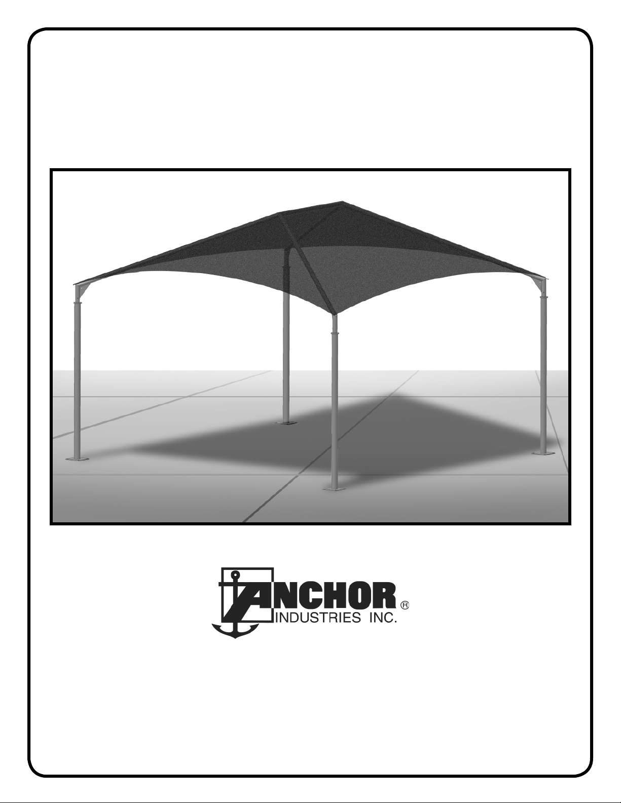
Assembly Instructions
PS 1014
PRODUCTION FACILITIES:
EVANSVILLE, IN
PHONE: 800-322-8368
or 812-867-2421
FAX: 812-867-4636
EMAIL: [email protected]
www.anchorinc.com
SALES OFFICES:
7701 HIGHWAY 41 N
EVANSVILLE, IN 47725 USA
EC 4829
Perfectshade®

Warning: The Perfect Shade Structure is intended for concrete Install only. Installer is solely re-
sponsible for evaluating the quality of the concrete and its suitability for this structure.
Concrete installation surface must be level.
Manpower Required:
Three experienced installers should be able to assemble any size frame with fabric in two hours.
Caution:
Please read through this assembly manual completely before beginning your installation. Be sure the proper
equipment and safety precautions are in place. We hope that you enjoy the design features of the Perfect Shade
Structure.
1. Be aware to avoid contact of frame sections with any overhead power lines near the site.
2. Consult the local utility company prior to installation in order to avoid all underground power lines and gas
lines or other utility easements.
3. Keep site clear of debris to avoid tripping, especially while carrying frame parts or bundle of fabric.
4. When moving frame sections by hand, use proper lifting techniques to protect the back, and avoid pinching
fingers while making hardware connections.
5. Do not drag bundle of fabric on concrete, asphalt, or ground as this can cause damage to the fabric from abra-
sion through the bag.
6. The installation method described here requires coordination of tasks between workers. A safe installation is
dependent on that coordination. Work cooperatively as a team.
7. This tent is manufactured for use as a temporary sun shade structure. Evacuation is recommended if threaten-
ing or windy weather occurs.
Parts List
Part Name Qty. for (1)
Frame
Upright with Base Plate 4
Hip Weldment 4
Peak Weldment 2
Ridge Tube 1
Hex Head Cap Screw 1/2 x 3 1/4” 4
1/2” Nylock Nut 4
Fabric top in bag with wire rope & clamps 1
Installation Kit (purchased separately) 1
Hip Weldment
Ridge Tube
Fabric top Bag
with wire rope & clamps
attached to top.
Upright with
Baseplate
Peak Weldment
1/2” Nylock
Nut
1/2” Hex
Head Cap
Screw
Installation Kit
Come-a-long (2)
Pull Rope (2)
Eyebolt (2) Neoprene
Washer (4)
Wing nut
(2)
(4) Wire Rope
Clamps
(spares)
2

Step 1:
Choice of 1/2” diameter anchoring devices are at the discretion of the customer and not supplied by Anchor Indus-
tries.
Place anchoring devices as shown on the plan view below. (4) anchoring devices per base plate.
Note: For Your Convenience, (1) Template is supplied at the center of this manual.
Base Plate Layout
Base Plate
(Typ. 4)
Base Plate
(4) 3/4” dia. holes for
anchoring devices.*
Dimensions are to center
points of base plates un-
less noted otherwise.
*NOTE: The installer is
solely responsible for
determining the proper
anchoring device.
DIMENSION CHART
FOR BASE PLATE LAYOUT
Size A B C D E
10’ x 10’ 9’- 10” 9’-10” 10’-8 1/2” 10’-8 1/2” 13’-10 7/8”
10’ x 15’ 14’- 10” 9’-10” 15’-8 1/2” 10’-8 1/2” 17 -9 9/16”
10’ x 20’ 19’- 10” 9’-10” 20’-8 1/2” 10’-8 1/2” 22’-1 5/8”
15’ x 15’ 14’- 10” 14’-10” 15’-8 1/2” 15’-8 1/2” 20’-11 3/4”
20’ x 20’ 19’- 10” 19’-10” 20’-8 1/2” 20’-8 1/2” 28’-0 9/16”
20’ x 30’ 29’- 10” 19’-10” 30’-8 1/2” 20’-8 1/2” 35’-9 7/8”
“C” Ref. dimension
“A”
“E” Diagonal
“D” Ref. dimension
“B”
Corner AA
Corner BB Corner DD
Corner CC
Ridge
Frame shown in
dashed lines
Caution: Concrete installation
surface must be level.
3

Step 2
Layout frame members as shown above in their approximate final placement. (See base plate layout in Step 1)
Step 3
Stand one of the uprights over the installed anchors at Corner AA. (See Figure 2)
Warning: Examine the orientation of the upright so that when hip is attached it will be pointed toward the ridge. (See
Figure 3)
Step 4
Fasten the base plate to the anchors and tighten to snug. (See Figure 4)
Figure 4
Remove template
before base plate
installation.
Corner BB
1st Base Plate
Template
Corner AA
2nd Base Plate
Template taped to
concrete surface.
Ridge
Figure 2
Corner CC
Base Plate
Template Corner DD
Base Plate
Template
Upright
Slide hip down
over upright align-
ing holes.
Figure 3
Note that hole thru
top of upright is
perpendicular to
hip and aligns with
hole in hip.
Upright
Hip
Peak Weldments
Note the orientation of the corners to the ridge. Base plates
MUST be laid out in this order. -- AA, BB, CC and then DD.
Hip
Note: All uprights are iden-
tical, but proper orientation is
critical as noted in Step 3.
4
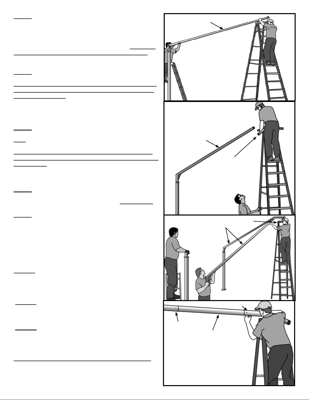
Step 5
Attach the first hip. Lift the Peak end of the hip up by climb-
ing a ladder (ladder placed at the approximate position of
the peak) (See Figure 5). Another person at the upright on a
ladder must direct the person at the peak end of the hip so
that it may be slipped into place on the upright. Make sure
the holes in the upright are aligned with those in the hip.
(See Figure 3) Loosely install bolt at hip to upright.
Step 6
Attach the Peak weldment to the hip. (Figure 6)
Warning: Examine the orientation of the peak weldment so
that the angles of the hips and ridge look to be pointing in
the proper directions.
Do not insert the bolt until later. For safety reasons, have
the person at the peak stay at that position until all hips are
installed.
Step 7
Erect the second upright at Corner BB. The second upright
must be oriented as shown in Base Plate Layout and Figure
2.
Warning: Again examine the orientation of the upright so
that when hip is attached it will be pointed toward the ridge.
(See Figure 3)
Fasten the base plate to the anchors but with only a loose fit
at this time for aid in installation.
Step 8
Lift the peak end of the second hip up and place on the peak
weldment. Do not insert the bolt until later. (See Figure 7)
Step 9
It may be necessary to lean or tip the upright to align it so
that the hip can be slipped over the top of the upright. Once
the hip is on the upright, check to be sure that the holes in
the hip line up with the holes in the upright. If they do not
align, your upright may be turned incorrectly.
Loosely install bolt at hip to upright.
Tighten the base plate anchors to snug.
Step 10
Bolt the ridge tube to the peak weldment. Bolt the other
peak weldment to the other end of the ridge tube. (See
Figure 8)
Step 11
Erect the third and fourth uprights (corners CC and DD).
Follow the instructions from Step 7 thru Step 9.
Step 12
Insert bolts for peak weldment into remaining hips. Tighten
all base plate bolts and tighten the bolts and nuts from the
hips to the uprights at this time.
The Frame portion of the Perfect Shade is complete.
Figure 8
Ridge
Figure 5
Peak
Figure 6
Figure 7 Peak
Hips
Hip
Hip
Peak
Peak
Note: 12’ ladder used
at peak for 20’ frame.
Shorter ladder may
be used on smaller
frames
5
Other Anchor Indoor Furnishing manuals

Popular Indoor Furnishing manuals by other brands

Regency
Regency LWMS3015 Assembly instructions

Furniture of America
Furniture of America CM7751C Assembly instructions

Safavieh Furniture
Safavieh Furniture Estella CNS5731 manual

PLACES OF STYLE
PLACES OF STYLE Ovalfuss Assembly instruction

Trasman
Trasman 1138 Bo1 Assembly manual

Costway
Costway JV10856 manual


