Anders DX Starterkit-T335 User manual

Page 1of 14
Starterkit-T335
Quick Start Guide
Doc Number: DX1B_QSG01
Issue 2
Introduction
Starterkit-T335 is an all in one evaluation kit
allowing you to begin the development of
your product quickly and easily.
The embedded platform comprises a choice
of high-performance PCAP multi-touch TFT
displays, pre-integrated with a Texas
Instruments T335 single-core Cortex-A8 CPU
module.
The evaluation kit contains all the necessary
accessories you need meaning you can get off
to a flying start.
Key Features
•Scalable solution for next generation devices.
Projected Capacitive Touchscreen Displays
ARM based 1GHz processor
Graphics acceleration
Multiple I/O, Communications
•1GHz processor
4.3’’or 7.0” display choice
Linux OS with GUI development tool
ARM Cortex-A8 CPU

Page 2of 14
Document History
Date
Revision
ECN
Description
Authored
Approved
23/3/2017
A
N/A
Document created
C. Madella
Product
Manager
05/04/2017
B
N/A
Modified descriptions
for DX1B and added
pictures
L.C. Tran
Product
Manager
06/04/2017
1
N/A
First Release
L.C. Tran
Product
Manager
28/04/2017
2
N/A
Product name
changed
Cover Page updated
Layout updated
Display features
added
Mechanical
Information added
Support links changed
G. Losito
Product
Manager
11/12/2017
3
N/A
Support links changed
G. Losito
Product
Manager

Page 3of 14
Contents
DOCUMENT HISTORY..................................................................................................................................................... 2
1INTRODUCTION .................................................................................................................................................... 4
1.1 PURPOSE ........................................................................................................................................................................4
1.2 SCOPE ............................................................................................................................................................................4
1.3 TECHNICAL ASSISTANCE .....................................................................................................................................................4
1.4 REFERENCE .....................................................................................................................................................................4
2PACKAGE DESCRIPTION......................................................................................................................................... 5
2.1 PACKAGE CONTENT ..........................................................................................................................................................5
3MECHANICAL INFORMATION ................................................................................................................................ 7
3.1 CARRIER BOARD:..............................................................................................................................................................7
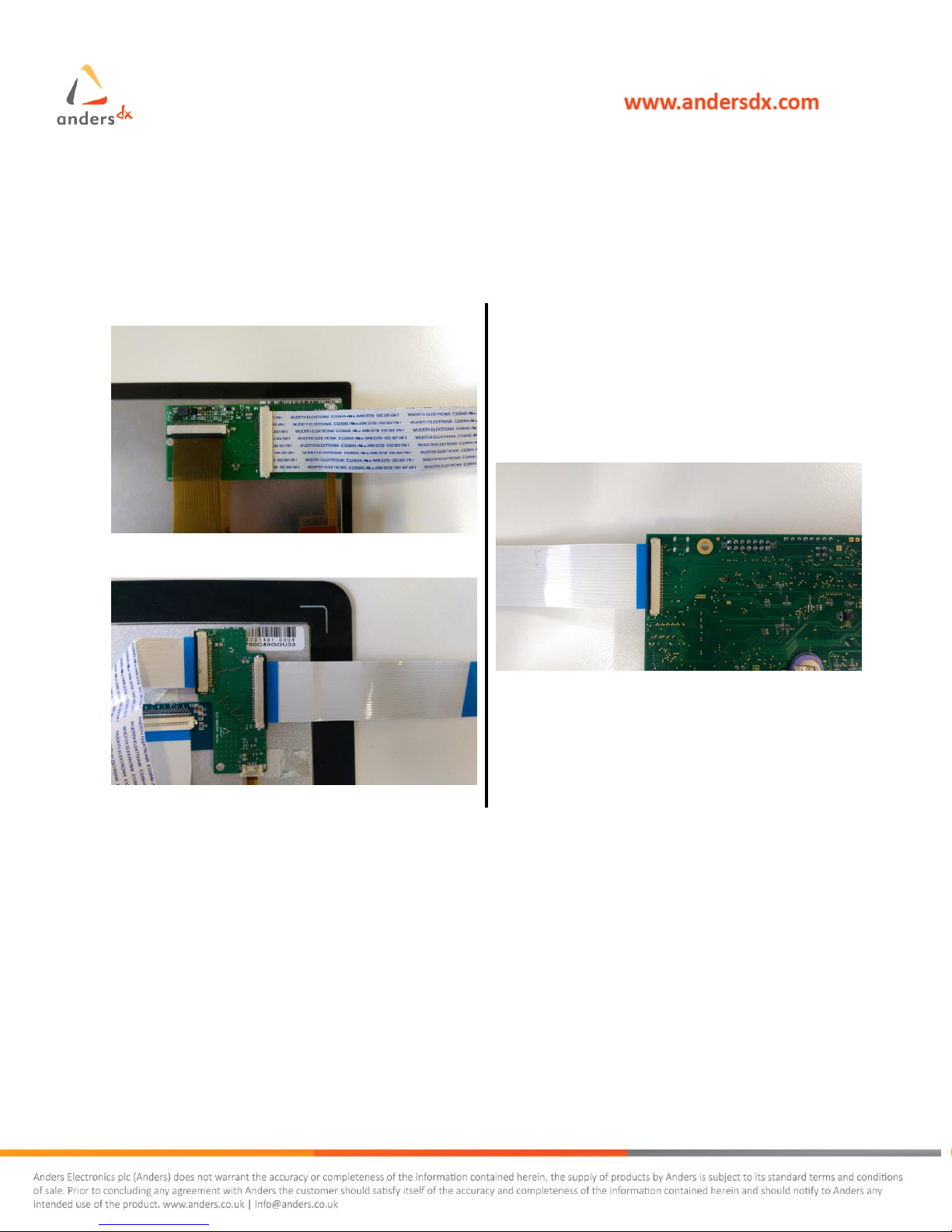
4ASSEMBLY AND BASIC SET-UP............................................................................................................................... 8
4.1 DISPLAY AND BASE BOARD CONNECTIONS.............................................................................................................................8
4.2 CORE MODULE CONNECTION .............................................................................................................................................9
4.3 FINAL ASSEMBLED UNIT ....................................................................................................................................................9
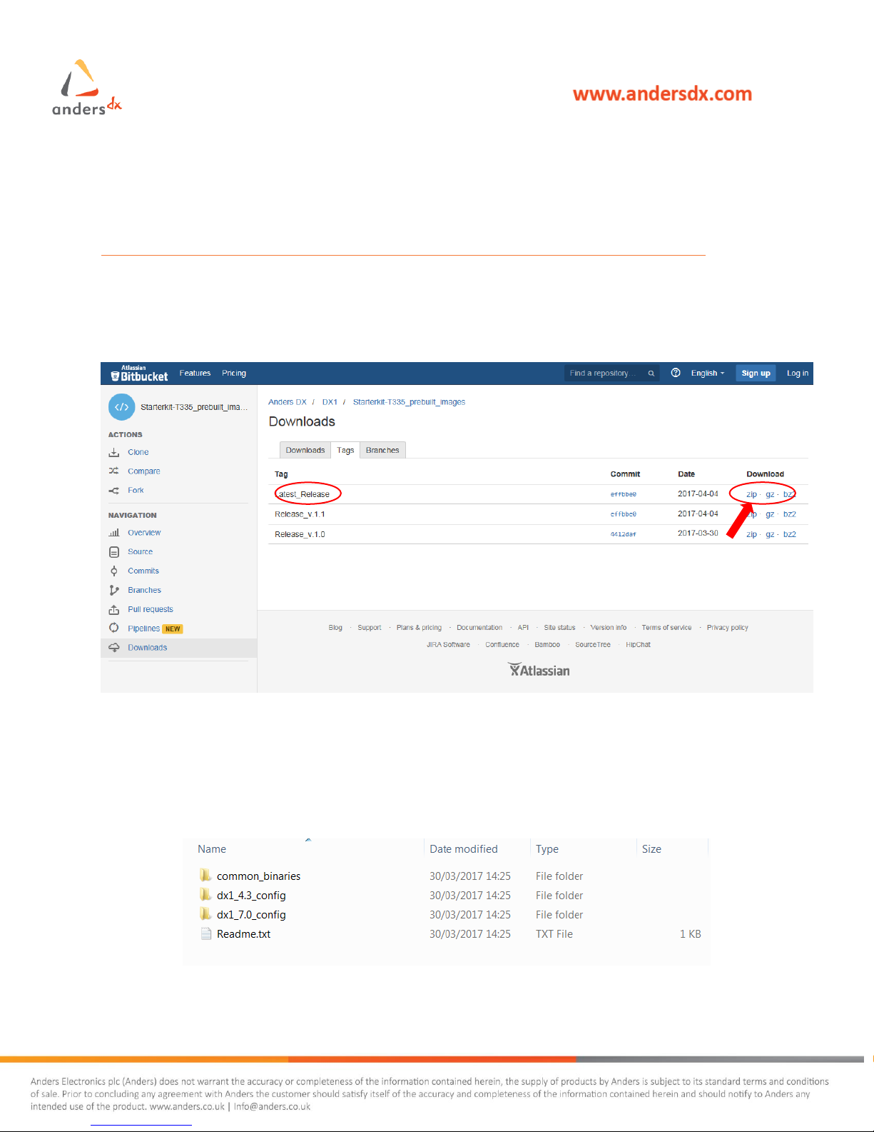
5INSTALLING SOFTWARE IMAGE........................................................................................................................... 10
5.1 DOWNLOAD IMAGES.......................................................................................................................................................10
5.2 PLACE THE CONTENT ON SD CARD .....................................................................................................................................10
5.3 INSTALL THE IMAGE ONTO THE DEVICE ................................................................................................................................11
6BOOT UP AND DEVICE CONTROL......................................................................................................................... 13
7SUPPORT RESOURCE........................................................................................................................................... 14

Page 4of 14
1Introduction
1.1 Purpose
This document is an introduction to the use of our Starterkit-T335 product range.
1.2 Scope
This document is intended for all users that receive the platform for the first time.
1.3 Technical Assistance
For more technical details, please visit the Starterkit-T335 Product Wiki Page:
https://andersdx.atlassian.net/wiki/display/PRODDX1A/Starterkit-T335+Home
or access our Customer Support portal for any issues and queries:
https://andersdx.atlassian.net/servicedesk/customer/dxsup
1.4 Reference
None

Page 5of 14
2Package Description
The Starterkits-T335 is an all in one embedded solution with multi-touch display. The platform
comprises high-performance PCAP multi-touch TFT displays pre-integrated with a Texas
Instrument T335 single-core Cortex-A8 CPU module and it supports 2 display variants:
Size
Features
Resolution
Touch
Orientation
Viewing Angle
(T/B/L/R)
Contrast
Ratio
Brightness
4.3”
480 x 272
(WQVGA)
PCAP
Landscape
50/70/70/70
600:1
570
cd/m2
7”
800 x 480
(WVGA)
PCAP
Landscape
80/80/80/80
600:1
400
cd/m2
The evaluation kit contains all the necessary accessories and offers an easy start base for the
development of your product.
Note: Please, ensure you observe ESD precautions when handling this product.
2.1 Package Content
Common content:
Package content
Part Number
DX-1 Carrier board
ELC-00241-1
TI AM335x based Core Module
CM-T335-Dx-Cx-Nx-[E]-[A]-[Ux]-[WB]-[Tx]
Accessory Package for DX1 range
DX1B-ACC
This Quick Start Guide
DX1A_QSG01

Page 6of 14
4.3” display specific content:
Package content
Part Number
4.3" WQVGA TFT MODULE CUSTOM CTP
SCX0403C32GGC06
Interface Kit required to Integrate 4.3"
WQVGA (SCX0403C32GGC06) Display
IK1B-001A
7” display specific content:
Note: Please, make sure to have both the Part Number and the Serial Number handy when you
contact Anders DX for provisioning and issue support.
Package content
Part Number
7” WVGA PCAP TFT Display
SCF0700C48GGU33
Interface Kit required to Integrate 7"
WVGA (SCF0700C48GGU33) Display
IK1B-002A

Page 7of 14
3Mechanical Information
3.1 Carrier Board:
Rear IO panel
Front Side Diagram

Page 8of 14
4Assembly and Basic Set-Up
4.1 Display and Base Board Connections
Connect the FFC as followed:
4.3” Display
Baseboard
7.0” Display

Page 9of 14
4.2 Core Module Connection
4.3 Final Assembled Unit
Insert and push in
Push down

Page 10 of 14
5Installing Software Image
5.1 Download Images
Starterkits-T335 Pre-built Images for all variants can be found at below link:
https://bitbucket.org/andersdx/starterkit-t335_prebuilt_images/downloads/?tab=tags
It’s always advisable to download the latest release which will have a correspondent label
“Latest_Release”. You can choose among .zip, .gz or .bz2 file format.
5.2 Place the content on SD Card
Unzipping the downloaded file locally, the content should look like in the picture below and the
Release_notes.txt will give you additional information on the content and the changes for the
specific revision:
Download buttons

Page 11 of 14
Then format a standard SD-Card as FAT16 or FAT32 file system if not yet done and copy the
content of the “common_binaries” folder in the root of the SD-Card.
Finally, pick the specific configuration script “boot.scr” from the corresponding folder of your
Display size “dx1_XXX_config”. (4.3” or 7.0”) and place it in the SD-Card along with the common
files.
The root folder of your SD-Card should contain the files as pictured below:
5.3 Install the Image onto the device
To install the SW into the device, place the pre-loaded SD-Card into the SBC slot while the unit is
off and then plug in the power cable and press the power on button [SW1] to switch on the unit.
The automatic installation will run and the board will be fully programmed and configured in about
15 minutes. After installation is completed, remember to extract the SD-Card and power cycle the
device.
You can follow the installation process details through the debug port [P11]:
1. Connect the serial cable provided to a RS232* port on your host PC and the other end to the [P11]
connector.
2. Open a terminal emulator session from the host PC to access the COM port you attached the device to
and apply following settings: 115200, 8, N, 1 and No HW/SW Flow Control (Putty emulator is pictured
below as reference)

Page 12 of 14
NOTE: *Some PC may not have a RS232 port available. Use commercially available RS232 to USB
converter instead.
3. The terminal emulator will display bootloader debug traces while installing. The installation will be
completed once the following messages are displayed:

Page 13 of 14
6Boot Up and Device Control
1. Plug in the power supply and press the switch [SW1]. A green LED [DS1] on the baseboard will be
persistently on showing that it is properly powered on and another green LED [DS1] on the core
module will be blinking indicating that there is activity.
2. The device with Anders SW image installed will load automatically displaying Anders boot logo first and
then switching to the main Debian Desktop. A basic Demo application may run to show off some of the
features of the touchscreen and display.
3. The SW image includes a preconfigured bootloader and a preconfigured Linux distribution. A Linux
console access is available through the same debug serial port described in section 4.3.
4. The terminal emulator will display kernel messages while loading and the console access will then be
provided with default user and password:
Login: root
Password: 111111

Page 14 of 14
7Support Resource
For more technical information and detailed user-guides, please check our Starterkits-T335
Product Wiki Page:
https://andersdx.atlassian.net/wiki/spaces/PRODDX1A/overview
or access our Customer Support portal for any issues and queries:
https://andersdx.atlassian.net/servicedesk/customer/dxsup
Table of contents