Front and Rear Panel Connections 2-2 Rear Panel
MN25131A OM PN: 10410-00783 Rev. A 2-3
2-2 Rear Panel
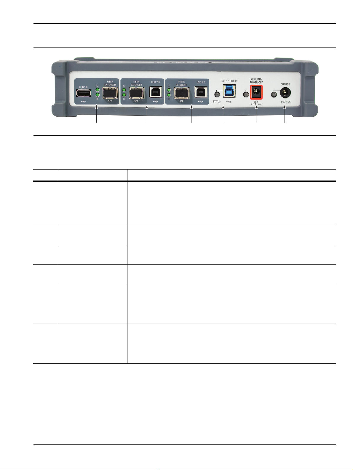
Figure 2-2. MN25131A Rear Panel Connectors
Table 2-2. MN25131A Rear Panel Connectors
Ref Name Function
1 FIBER EXTENDER USB Type A to SFP Optical Fiber Converter
S (send) and R (receive) LEDs indicate Activity on the Fiber Outputs
This converter enables the system power only when optical power is sensed
at its SFP input. (See functional description in Section 3-8 “USB to SFP
Optical Fiber Converters” on page 3-4.
2 FIBER EXTENDER USB Type-B to SFP Optical Fiber Converter
S and R LEDs indicate Activity on the Fiber Outputs
3 FIBER EXTENDER USB Type-B to SFP Optical Fiber Converter
S and R LEDs indicate Activity on the Fiber Outputs
4 USB 3.0 IN USB Type-B Input to Front Panel HUB
- Status LED is Green when bus activity is present.
5 +20 V + 20 V Power Supply
- LED turns green when a connector is inserted.
- LED will turn orange when > 2.3 A is drawn.
- LED will extinguish when > 2.5 A is drawn.
6 CHARGE External Supply Input
- Charge indicator is green if input voltage is > 15 V.
- Charge indicator is orange if input voltage is < 15 V.
- Charge rate is 4 Amps.
12 6543