Worx Landroid RadioLink WA0864 Specification sheet

Owner’s manual
WR153E
WR155E
Original instruction
WA0864
L
WA0864

Table of contents EN
2
Welcome
Contact information
Safety first
Important safety instructions
Get familiar with
What’s in the box
How works
Getting started
Installation
Quick reference
Troubleshooting
Technical data
Declaration of Conformity
p. 03
p. 05
p. 07
p. 08
p. 09
p. 24
p. 25
p. 26
TABLE OF CONTENTS

Welcome EN
3
Thank you for purchasing a Worx Landroid RadioLink.
Support
www.worx-europe.com/support
Landroid Owner’s Site
https://account.worxlandroid.com/login
We’re here to help:

Safety first EN
4
IMPORTANT SAFETY INSTRUCTIONS
RadioLink Gateway and Node - General Safety Warnings
WARNING: Read all safety warnings and all instructions.
Failure to follow the warnings and instructions may result in electric shock, fire and/or serious injury.
Carefully read the instructions for the safe operation of the machine.
Save all warnings and instructions for future reference.
RF exposure requirements
To satisfy RF exposure requirements, a separation distance of 200mm or more should be maintained between this
device and persons during device operation. Operations at a closer distance are not recommended.
The antenna used for this transmitter must not be co-located in conjunction with any other antenna or transmitter.
Maintenance
Have your equipment serviced by a qualified repair person using only identical replacement
parts. This will ensure that the safety of the equipment is maintained.
Restrictions on putting into service
There are no restrictions of use.
Symbols
Warning
Read the operator’s manual.
Waste electrical products should not be disposed of with household waste.
Please recycle where facilities exist.
Check with your Local Authorities or retailer for recycling advice.

Safety first EN
5
AC adapter - General Safety Warnings
WARNING: Read all safety warnings and all instructions.
Failure to follow the warnings and instructions may result in electric shock, fire and/or serious injury.
Save all warnings and instructions for future reference.
This appliance can be used by children aged from 8 years and above and people with reduced physical, sensory
or mental capabilities or lack of experience and knowledge if they have been given supervision or instruction
concerning use of the appliance in a safe way and understand the hazards involved. Children shall not play with
the appliance. Cleaning and user maintenance shall not be made by children without supervision.
Additional Safety Warnings
a. The outlet should be close to the device and be easily accessible.
b. Do NOT use the device with a damaged cable or case.
c. Follow the technical data given by the manufacturer if you use the device.
d. Disconnect the device from the mains when it’s not in use.
e. Do not use the device for a different purpose than that for which it is designedf.
f. Max. ambient temperature 45°C.
g. The mains connection of this device can’t be replaced. If it is broken or damaged, the whole device must be
disposed of.
h. The device must not be exposed to splashing water, rain or humidity.
i. Vessels containing liquids such as vases should not be put on top of the device.
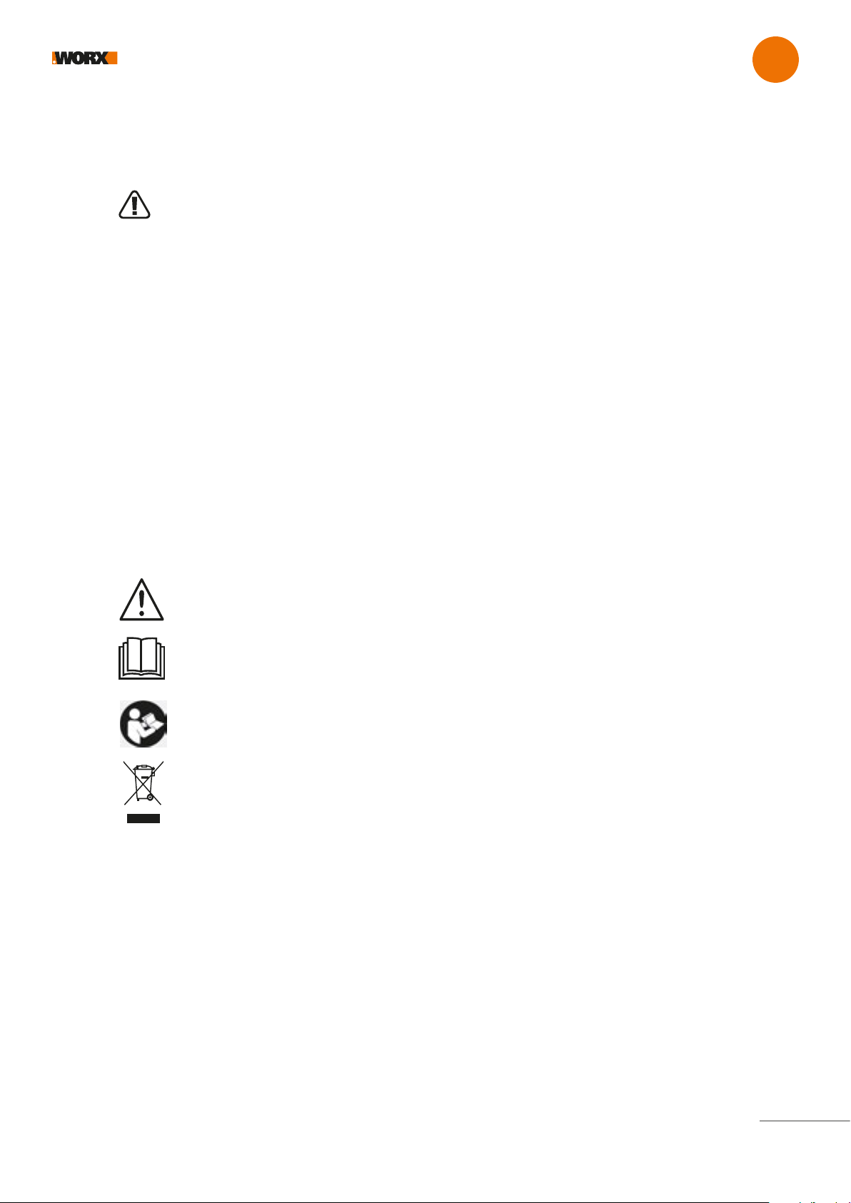
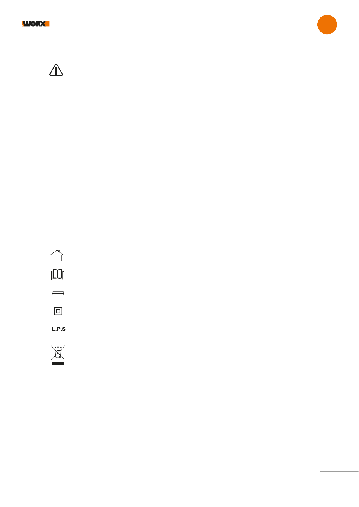
Symbols
For indoor use only
Read the operator’s manual.
Fuse
Double insulation
Low power supply
Waste electrical products should not be disposed of with household waste.
Please recycle where facilities exist.
Check with your Local Authorities or retailer for recycling advice.

Safety first EN
6
MAINTAIN External power supply WITH CARE
Remove the plug from the socket before carrying out any adjustment, servicing or maintenance.
Your External power supply requires no additional lubrication or maintenance. Never use water or chemical
cleaners to clean. Wipe clean with a dry cloth. Always store your External power supply in a dry place.
ENVIRONMENTAL PROTECTION
Waste electrical products should not be disposed of with household waste.
Please recycle where facilities exist.
Check with your Local Authorities or retailer for recycling advice.
Manufacturer: Mass Power Electronic Limited,
10/F, TOWER A, BILLION CENTER 1 WANG KWONG ROAD, KOWLOON BAY, KOWLOON, HONG KONG
Importer : Positec Germany GmbH
Grüner Weg 10, 50825 Cologne, Germany

Get familiar with EN
WHAT’S IN THE BOX
7
A
C
B
E
D
AC Adapter
RadioLink Gateway
RadioLink Module
Cable
Ethernet cable
A
B
C
D
E

Get familiar with EN
HOW IT WORKS
8
The RadioLink option offers constant online connectivity.
Regular domestic Wi-Fi networks typically only cover a fraction of the entire garden—RadioLink instead establishes a radio con-
nectivity that extends it from your Wi-Fi router, regardless of walls, obstacles or interferences.

9
Getting started EN
INSTALLATION
Before proceeding with the installation please make sure your Landroid’s firmware is updated to the last version. For more information on
firmware upgrade please refer to the “Maintenance” section of the Landroid-o-pedia (https://support.worx-europe.com).
RadioLink comes in two parts and is plug and play. Please follow the steps below depending on Landroid models you own.
1. Turn off Landroid 2. Open Landroid’s hood
3. Remove the cover using a screwdriver 4. Connect RadioLink module to the Landroid’s connector till you
hear a click and insert it into the slot
5. Replace the cover using a screwdriver 6. Close the hood
Landroid S 300 (WR130E)
2
OK
START
SET
1
CLICK!
4
3A
65

EN
10
7. Connect the RadioLink Gateway (B) to your router, even if it does
not have Wi-Fi, by just connecting the ethernet cable (E)
Getting started
9. The lights will be: UWB (Ultra Wide Band) light is red, Wi-Fi LAN
light is green, power light is blue. If not please check trouble shoo-
ting guide at the end of this manual.
12. Press OK button for 3 seconds
10. Push with a screwdriver in the hole, as per
image here above, till you hear a click
11. The lights will starts blinking multicolor/rainbow
8
8. Plug the AC adaptor (A) into the main plug and connect it to the
RadioLink Gateway (B) by using the cable (D).
A
E
D
9
B
10
11
OK
START
SET
3s
12

EN
11
Getting started
13. Press Home and the WI-FI symbol will appear together with the
“rL” wording into the display. Then press OK.
15. After a couple of minutes all 3 lights will turn solid green.
Please check the trouble shooting section for the different LED
colors and their meaning.
13
OK
START
SET
OK
START
SET
14
OK
START
SET
14. The display will show “SUcc” if everything is ne.
15 16
16. The RadioLink icon is now active.Touch it to see the status. If
the Status shows “error” contact our support team
at https://support.worx-europe.com

EN
12
Getting started
OK
START
SET
1 2
Landroid M 500 (WR141E)
1. Turn off Landroid 2. Open Landroid’s hood
3
CLICK!
4
A
3. Remove the cover using a screwdriver 4. Connect RadioLink module to the Landroid’s connector till you
hear a click and insert it into the slot
6
5
5. Replace the cover using a screwdriver 6. Close the hood

EN
13
Getting started
7. Connect the RadioLink Gateway (B) to your router, even if it
does not have Wi-Fi, by just connecting the ethernet cable (E)
12. Press OK button for 3 seconds
10. Push with a screwdriver in the hole, as per
image here above, till you hear a click
11. The lights will starts blinking multicolor/rainbow
8
8. Plug the AC adaptor (A) into the main plug and connect it to the
RadioLink Gateway (B) by using the cable (D).
A
E
D
9
B
10
11
OK
START
SET
3s
12
9. The lights will be: UWB (Ultra Wide Band) light is red, Wi-Fi
LAN light is green, power light is blue. If not please check trouble
shooting guide at the end of this manual.

EN
14
Getting started
15. After a couple of minutes all 3 lights will turn solid green.
Please check the trouble shooting section for the different LED
colors and their meaning.
13
OK
START
SET
OK
START
SET
14
OK
START
SET
14. The display will show “SUcc” if everything is ne.
15 16
16. The RadioLink icon is now active.Touch it to see the status.
If the Status shows “error” contact our support team
at https://support.worx-europe.com
13. Press Home and the Wi-Fi symbol will appear together
with the “rL” wording into the display. Then press OK.

EN
15
Getting started
Landroid M 700 (WR1421E)
Landroid M 1000 (WR143E)
START OK
A
BC D
Power OFF
Goodbye
21
1. Turn off Landroid 2. Open Landroid’s hood
3
CLICK!
4
A
3. Remove the cover using a screwdriver 4. Connect RadioLink module to the Landroid’s connector till you
hear a click and insert it into the slot
6
5
5. Replace the cover using a screwdriver 6. Close the hood

16
EN
Getting started
7. Connect the RadioLink Gateway (B) to your router, even if it
does not have Wi-Fi, by just connecting the ethernet cable (E)
10. Push with a screwdriver in the hole, as per
image here above, till you hear a click
8
8. Plug the AC adaptor (A) into the main plug and connect it to the
RadioLink Gateway (B) by using the cable (D).
A
E
D
9
B
10
11
START OK
A
BC D
Wed.11/29 09:00PM
12
11. The lights will starts blinking multicolor/rainbow 12. Select “General setting” from the display menu and press OK
9. The lights will be: UWB (Ultra Wide Band) light is red, Wi-Fi LAN
light is green, power light is blue. If not please check trouble shoo-
ting guide at the end of this manual.

17
EN
Getting started
14. The wording “Press OK to start pairing RadioLink – Gateway”
will appear, press OK
15. The message “Pairing successful!” will appear on display 16. After a couple of minutes all 3 lights will turn solid green.
Please check the trouble shooting section for the different LED
colors and their meaning.
START OK
A
BC D
General setting
Set date & time
Rain start delay
Setup WIFI
Setup Radio Link
13
13. Choose “Select RadioLink” by using the arrow and press OK
START OK
A
BC D
14
Setup Radio Link
Press “OK”
to start pairing
Radio Link - Gateway
START OK
A
BC D
15
Setup Radio Link
Pairing successful !
16
17
17. The RadioLink icon is now active.Touch it to see the status.
If the Status shows “error” contact our support team
at https://support.worx-europe.com

18
EN
Getting started
Landroid L 1000 (WR147E)
1. Turn off Landroid 2. Turn Landroid upside down
2
OK
START
SET
1
START OK
A
BC D
Power OFF
Goodbye
1
2
3
CLICK!
4
A
6
5
3. Remove the cover using a screwdriver 4. Connect RadioLink module to the Landroid’s connector till you
hear a click and insert it into the slot
5. Replace the cover using a screwdriver 6. Replace Landroid to its position

19
EN
Getting started
7. Connect the RadioLink Gateway (B) to your router, even if it
does not have Wi-Fi, by just connecting the ethernet cable (E)
10. Push with a screwdriver in the hole, as per
image here above, till you hear a click
8
8. Plug the AC adaptor (A) into the main plug and connect it to the
RadioLink Gateway (B) by using the cable (D).
A
E
D
9
B
10
11
11. The lights will starts blinking multicolor/rainbow
9. The lights will be: UWB (Ultra Wide Band) light is red, Wi-Fi
LAN light is green, power light is blue. If not please check trouble
shooting guide at the end of this manual.
OK
START
SET
3s
12
12. Press OK button for 3 seconds

20
EN
Getting started
15. After a couple of minutes all 3 lights will turn solid green.
Please check the trouble shooting section for the different LED
colors and their meaning.
15
16
16. The RadioLink icon is now active.Touch it to see the status.
If the Status shows “error” contact our support team
at https://support.worx-europe.com
13
OK
START
SET
OK
START
SET
14
OK
START
SET
15
16
13. Press Home and the Wi-Fi symbol will appear together
with the “rL” wording into the display. Then press OK.
14. The display will show “SUcc” if everything is ne.
Table of contents
Popular Extender manuals by other brands

Rose electronics
Rose electronics CrystalView Exact Installation and operation manual

NETGEAR
NETGEAR AX1800 EAX14 user manual

WifiTrax Model Science
WifiTrax Model Science WFD-46 Getting started guide

ENFORCER
ENFORCER MVE-AHMPM-01NQ user manual

Vanderbilt
Vanderbilt SPCV340 manual

Appsys ProAudio
Appsys ProAudio ADX-32A user manual