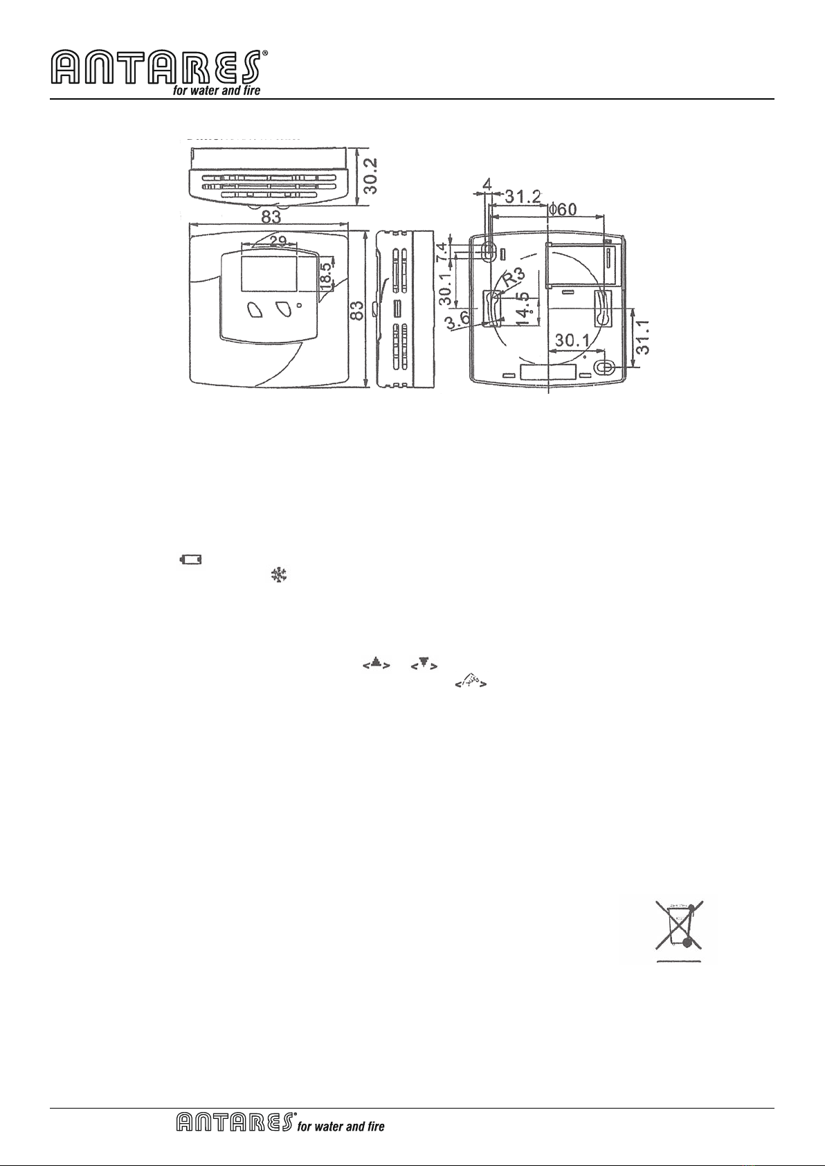
Antares T.225.00 User manual

Art. T.225.00
Termostato RF
A. INSTALLAZIONE E MONTAGGIO
Attenzione:
Prima dell’installazione del T.225.00, spegnere le apparecchiature da collegarvi (ad esempio ricaldamento).
Si raccomanda nella maniera più assoluta che l’installazione venga eseguita da personale qualicato.
1. Posizione di installazione:
Il termostato (ricevitore e trasmettitore) deve essere montato su una parete interna a 1,5 m dal pavimento in posizione
in cui è prontamente inuenzato da variazioni della temperatura generale della stanza con aria a circolazione libera.
Il luogo di montaggio deve essere pulito e asciutto in ambienti interni. Prevenire l’esposizione diretta alla luce solare;
area gocciolante o schizzi. Non posizionare questa unità in un luogo in cui la circolazione dell’aria è bassa o in cui
presenta forti variazioni di temperatura (ad es. Vicino alla porta). Non posizionare il termostato vicino a fonti di calore /
freddo.
2. Cablaggio per ricevitore:
Attenzione: spegnere i dispositivi elettrici e il ricevitore prima del cablaggio.
Ci sono 2 terminali di cablaggio (N, L e 1, 2) nella parte inferiore di T.225 (Ricevitore). Collegare il riscaldamento ai
terminali “1” e “2” e collegare 240 Vac a “N” e “L”.
Cablare i cavi corretti alla morsettiera secondo lo schema elettrico collegato all’interno del coperchio superiore del
termostato.
Per l’installazione, non vi sono condotti o cavi metallici dotati di una guaina metallica nella scatola a parete.
Spingere tutti i cavi nella parete prima del ssaggio per evitare di intrappolare i li.
Si raccomanda di installare un fusibile di 10A.
Etichetta di connessione morsettiera – ricevitore
3. Montaggio:
Utilizzando le viti accessorie e gli ancoraggi a parete forniti, montare T.225 con il foro per chiave sul retro. Il
trasmettitore e il ricevitore devono essere montati a parete
Installare o sostituire la batteria per il trasmettitore:
Attenzione: sostituire solo con batterie dello stesso tipo o equivalenti. Non gettare le batterie usate nei riuti domestici.
Fare riferimento alla propria area locale per lo smaltimento corretto.
T.225 – installazione trasmettitore
Usare un cacciavite piatto
premere sul divario in
entrambe le parti per
staccare il guscio
anteriore.
1 Estrarre il cassetto batteria
2 Collocare le nuove batterie in base alla marcatura sul vano batterie.
3 Smaltire correttamente le vecchie batterie.
4 Riportare il vano batterie nella sua posizione.
5 Controllare se il termostato funziona correttamente o meno. Premere “RST” se necessario.
(Figura 1)
Fusibile
Caldo
IT

Art. T.225.00
Dimensioni in mm
B. Avvio / Ripristino:
1. Dopo il cablaggio e il montaggio, spegnere tutti i dispositivi collegati. Posizionare 2 nuove batterie alcaline AAA da
1,5 V in base alle polarità contrassegnate. Il display LCD verrà acceso.
2. Premere “RST” per ripristinare. Il T.225 sarà pronto e sincronizzato.
3. Quando la temperatura impostata sarà maggiore di quella d’ambiente, il termostato darà il consenso al
riscaldamento. Il simbolo del termometro visualizzato sul display LCD lampeggerà ntanto che la temperatura
ambiente non raggiungerà la temperatura impostata.
C. Modalità di funzionamento
1. Viene avviata la rilevazione della temperatura e sul display LCD viene visualizzata la temperatura ambiente.
2. Se la batteria è scarica comparirà il simbolo . Le batterie vecchie devono essere sostituite immediatamente
con batterie nuove.
3. La funzione di scongelamento viene attivata quando viene visualizzata una temperatura di 5 ° C o inferiore.
L’uscita sarà forzata su ON @ Heat.
4. Al di sotto di 0 °C, il trasmettitore visualizzerà LO.
5. Oltre i 40 °C, il trasmettitore visualizzerà HI.
D. Impostazione della temperatura:
1. Selezionare la temperatura confortevole premendo o sulla temperatura desiderata.
2. Riportare il display della temperatura ambiente dopo 10 secondi con l’icona scompare.
E. Impostazione frequenza segnale:
Nel trasmettitore e nel ricevitore sono presenti degli switch per selezionare la frequenza del segnale. Il ricevitore e il
trasmettitore non si sincronizzeranno se gli switch non saranno impostati sulla stessa frequenza.
F. Speciche
1 Temperatura misurata 0 - 40°C (0.5°C/step)
2 Precisione ± 0.5°C
3 Range temperature impost.: 5.0 – 35.0°C (0.5°C/step)
4 Terminali 2.5 mm2 cavo
5 Classica controllo classe II
6 Funzionamento micro disconnessione su operazione
7 Controllo elettronico Tipo 2.B
8 Trasmettitore – batterie 2x1.5V AAA alcalina
9 Ricevitore – alimentazione 240Vac
10 Ricevitore alimentazione uscita 24 240 Vac 50/60Hz 10 (3)A max
11 Temperatura funzionamento 0 - 50°C
12 Temperatura stoccaggio -10 - 60°C
13 Sensore 103AT-2B NTC termistore
- Via degli Alpini, 144 - 55100 Lucca - Italy
raccolta differenziata per
apparecchiature elettriche
ed elettroniche
Termostato RF
IT

Art. T.225.00
RF Thermostat
A. Installation, Mounting:
Caution: Turn off T.225 and the devices which will be connected before installation.
It is highly recommended that the installation procedure is processed by trained personnel.
1. Installation Location:
The thermostat (Receiver and Transmitter) should be mounted on an inner wall 1.5m above the oor in position where
it is readily affected by changes of the general room temperature with freely circulating air. The mounting place must
be clean and dry indoor places. Prevent direct exposure to sunlight; dripping or splashing area. Do not place this unit
at a location where air circulation is low, or where it has great temperature changes (e.g. near door). Do not place the
thermostat near heat/cool generating sources.
2. Wiring for Receiver:
Caution: Turn off the electrical devices and receiver before wiring.
There are 2 wiring terminals (N, L and 1, 2) at the bottom of T.225 (Receiver). Connect heater to the “1” and “2”
terminals and connect 240Vac to “N” and “L”.
Wire the correct cables to the terminal block according to the circuit diagram which is attached inside the thermostat
top cover.
For installation, no metal conduits or cables provided with a metal sheath in the wall box.
Push all cables back into wall prior to xing to avoid trapping wires.
It is recommended that a 10A fuse be tted.
Terminal block connecting Label -- Receiver:
3. Mounting:
Using the accessory screws and wall anchors provided, mount T.225 with the key-hole at the back. The Transmitter
and receiver should be mounted on the wall
Install or replace the battery for transmitter:
Caution: Replace only with the same or equivalent type of batteries. Do not dispose the used batteries with household
waste. Refer to your local area for the proper disposal.
T.225 – Transmitter installation
Use a at screwdriver
to press on the gap at
both sides to detach
the front shell.
1 Pull out the battery drawer
2 Place the new batteries according to the marking on the battery drawer.
3 Dispose the old batteries properly.
4 Slide the battery drawer back to its position.
5 Check if the thermostat works properly or not. Press “RST” if necessary.
(Figure 1)
Fuse
Heat
EN

Art. T.225.00
Dimension in mm
B. Start/Reset:
1. After wiring and mounting, switch off all the connected devices. Place 2 new AAA 1.5V alkaline batteries according
to the polarities marked. LCD display will be switched on.
2. Press ‘RST’ to reset. The T.225 will be ready to control the heater / cooler.
3. When the set temperature is higher than the room temperature, the thermometer will consent to heating. The icon
of the thermometer visualized on the LCD display will ash until the room temperature will reach the one set.
C. Function mode
1. Temperature detection starts and LCD displays the room temperature.
2. If Battery is LOW, will be on. The old batteries must be replaced with new one immediately.
3. Defrost function is activated with displayed when temperature is 5°C or below. Output will be forced to ON @
Heat.
4. Below 0°C, transmitter will display LO.
5. Above 40°C, transmitter will display HI.
D. Temperature setting up:
1. Select the comfortable temperature by pressing or to the desirable temperature.
2. Return the room temperature display after 10 seconds with the icon disappears.
E. Setting the frequency signal:
In the transmitter and receiver there are switches present to enable the choice of signal frequency. The receiver and
the trasmitter will not synchronize if the switches are not set on the same frequency.
F. Specication
1 Temperature measurement: 0 - 40°C (0.5°C/step)
2 Accuracy: ± 0.5°C
3 Temperature control range: 5.0 – 35.0°C (0.5°C/step)
4 Terminals: 2.5 mm2 cable
5 Classication of control: Class II
6 Purpose of control: Micro-disconnection on operation
7 Electronic control: Type 2.B
8 Transmitter — Battery: 2x1.5V AAA alkaline battery
9 Receiver — input voltage: 240Vac
10 Receiver — output voltage: 24 240 Vac 50/60Hz 10 (3)A max
11 Operating temperature: 0 - 50°C
12 Storage temperature: -10 - 60°C
13 Sensing Element: 103AT-2B NTC thermistor
- Via degli Alpini, 144 - 55100 Lucca - Italy
separate collection for
electrical and electronic
equipment
RF Thermostat
EN
Table of contents
Languages:
Other Antares Thermostat manuals