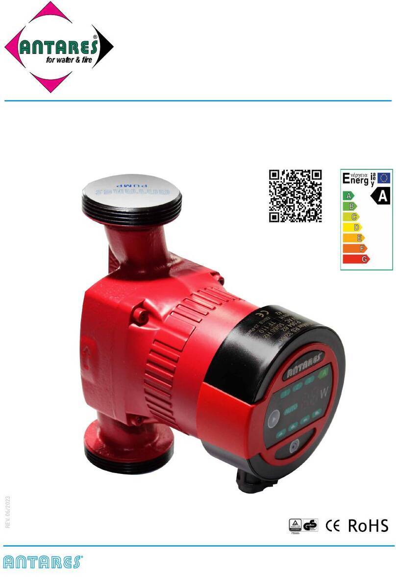
Antares HOTMATIC 15-1.5 User manual

ANTARES
®
for water & re S.r.l. - Via degli Alpini, 144 - 55100 Lucca - Italia
Tel: 0583 473701 - Fax: 0583 494366 - ant3@antaresint.com - www.antaresint.com
for water & fire
HOTMATIC 15-1.5
Energy-saving Microcirculation Pump
INSTALLATION AND OPERATING INSTRUCTIONS
ANTARES®for water & re S.r.l.- Via degli Alpini, 144 - 55100 Lucca - ITALIA
Rev. 062023
P.095.00

P.064P.095.00
EN 2
EN
Precautions for use:
1. Read the installation manual carefully before installation and use.
2. The manufacturer will not be liable for any personal injury, motor pump damage and other property
damage due to failure to comply with contents specied in safety warning signs.
3. The installers and operators must comply with local safety regulations.
4. The user must conrm that only qualied personnel with professional certication and prociency of
this manual is allowed to install and maintain this product.
5. The motor pump must not be installed in a place that is damp or may be splashed by water.
6. For convenient access of maintenance, a shut-off valve shall be installed on each side of inlet and
outlet of the motor pump.
7. The power supply of the motor pump shall be cut off before installation and maintenance.
8. For circulation of domestic hot water, copper or stainless steel motor pump body shall be used.
9. Heat supply pipelines shall not be frequently lled with non-softened water so as to avoid increasing
calcium in the circulating water inside the pipeline, which may thus block the impeller.
10. Do not start the pump without pumping liquid.
11. Pumping liquid may be high-temperature and high-pressure; therefore, the liquid in the system must be
completely drained or the shut-off valves on both sides must be closed before moving and dismantling
the pump to prevent burning.
12. Ventilation must be ensured in summer or high room temperature period to avoid condensation that
may cause electrical malfunctions.
13. If in winter, the pump system does not work or when the room temperature drops below 0°C, liquid in
the piping system shall be completely drained so as to avoid frost cracking of motor pump body.
14. If the pump is left unused for a long time, please close the pipe valve in the inlet and outlet of the pump
and cut off the power supply of pump.
15. If the flexible cable is damaged, it must be replaced by a qualied person.
16. Please close the valve at the inlet of motor pump and cut off power of the motor pump immediately
if overheating and abnormality of motor is detected, and contact your supplier or service center
immediately.
17. If trouble shooting cannot be addressed according to the manual, please close the valves on the inlet
and outlet of the motor pump immediately, cut off power supply of the motor pump and contact your
supplier or service center immediately.
18. The product should be placed out of the reach of children, after installation, isolation measures should
be taken to prevent children from touching.

P.064P.064
P.095.00
3 EN
EN
1 - Symbol description
2 - Overview
The pump is easy to install maintenance-free, low noise automatic regulation performance
which is the best choice for hot-water circulation system.
Main application:
1. Heating and Domestic hot-water circulation system
2. Calorier circulation system
3. Domestic sewerage system.
19. The product should be placed in a dry, ventilated and cool place and stored at room temperature.
This product is not for the use of unqualied persons but for professional installers.
Warning:
Before installation, you must carefully read the installation and operation
manual. The installation and use of the equipment must comply with local
regulation and applicable operation standards.
Warning:
The use of this product is severely forbidden to children or persons with special
needs.
Warning:
Failure to comply with this safety instruction may lead to personal injury!
Failure to comply with this security declaration will likely cause failure or
damage to the equipment!
CAUTION
Notes or instructions facilitating the work and ensuring operational safety.
NOTE

P.064P.095.00
EN 4
EN
3 - Operation Conditions
4 - Installation
4.1 - Installation
3.1 - Power supply
Voltage 230V, frequency 50Hz, single-phase AC power.
3.4 - System pressure
The maximum is 1.0MPa (10 bar).
3.5 - Protection Level
IP44
3.7 - Pumping liquid
The pumping liquid must be thin, clean, non-corrosive and non-explosive liquid which shall not
contain any solid particles, ber or mineral oil, and the pump must denitely not be used to pump
inflammable liquid such as rapeseed oil and gasoline. If the circulation pump is used in a place
with relatively high viscosity, the pump has lower performance. So when choosing a pump, the
viscosity of liquid must be taken into account.
• When installing HOTMATIC 15-1.5 Microcirculationo pump, the arrow on the pump casing
indicates the flow direction of liquid through the pump.
• When installing the motor pump in the pipeline, two gaskets must be installed at the inlet
and outlet.
• During the installation, the shaft of motor pump must be horizontal.
3.2 - Room Temperature
Room temperature: 0°C ~ +40°C
3.3 - Medium (liquid delivery) temperature
Liquid delivery temperature: +2°C ~ 95°C.
To avoid condensation in terminal box and the stator, the temperature of liquid pumped by the
motor pump must be always higher than room temperature.
3.6 - Inlet pressure
To avoid damage to the motor pump bearing due to cavitation noise, the motor pump inlet
shall maintain the following minimum pressure:
Liquid temperature < 85 °C 95°C
Inlet pressure 0.05 bar 0.28 bar
0.5m head 2.8m head

P.064P.064
P.095.00
5 EN
EN
OK OK
OK
NO
NO

P.064P.095.00
EN 6
EN
5 - Electrical connection
Warning:
• The motor pump must be connected to an external power switch, and the
minimum space between all the electrodes is 3mm.
Electrical connection and protection shall comply with local codes and norms.
The motor pump needs no protection from external motor.
Check if the supply voltage and frequency are the same as parameters indicated
on the nameplate of the motor pump.
Connect the motor pump and power supply with the plug supplied together with
the pump.
After the power is supplied, the indicator lamp on the control panel is ON.

P.064P.064
P.095.00
7 EN
EN
6 - Control panel
7 - Control of motor pump
1
2
35
4
8
9
7
6
Position Descriptions
1 Indicating constant speed running mode
2 Indicating Auto operation mode
3 Indicating temperature control mode
4• Power indicated
• Running (or stop) time indicated in timing mode
5 Running (or stop) hours set in timing mode
6 Running (or stop) minutes set in timing mode
7 Power unit shown under normal operation
8• Switch on various running modes
• Increasing time in timing mode
9 Decreasing time in timing mode
7.1 - Constant speed running mode
7.2 - Auto operation mode
Pump runs in the constant speed when it is in constant speed running mode. Green light 1
as well as light 4 which is showing current power, will be always on while the light 7 will also
be on.
Pump will automatically exert necessary adjustment according to current systematic
performance when it is in the auto operation mode. Green light 2 as well as light 4 which is
showing current power, will be always on while the light 7 will also be on.

P.064P.095.00
EN 8
EN
7.3 - Indicating temperature control mode
Temperature sensor will obtain the feedback in terms of fluid temperature and make a
judgement on whether start or stop when it is in the indicating temperature control mode. In
such mode,pump will stop when temperature is over 50 centigrade, but it will run in constant
speed when temperature is below 36 centigrade. Green light 3, as well as light 4 which is
showing current power, will be on while the light 7 will also be on.
7.5 - Indication lamp area of power consumption of motor pump
After the power is connected, the monitor in Position 4 works.
During operation, the indicated value is in Watt, showing the actual power consumption of
the motor pump.
When the motor pump fails to work, the monitor indicates:
7.4 - Timing mode
To set the “TIMING MODE”, press the up arrow (8) until the 3 side LEDs go out and the time
(hours and minutes) is displayed alternately on the screen.
To set time slots, follow these steps:
1. Simultaneously press the arrow keys (8 and 9) until “F0” flashes.
2. Long press the down arrow (9) until the flashing letter “h” lights up. By moving with the
arrows you can set the hour (0–23)
3. After setting the hour, press the down arrow (9) again until the word “min” flashes. By
moving with the arrows you can set the minutes (0–59)
4. By pressing the down arrow key (9) again, you will return to the setting of the chosen
time band
5. With the up arrows (8) it is possible to set the time slots from F0 to F6
6. The xed times will be valid from Monday to Sunday
DISPLAY OF TIME SLOTS TIME (EX. SETTING)
F1 - Beginning 6:00 wake up
F2 - End 8:00 exit
F3 - Beginning 11:30 home
F4 - End 13:30 exit
F5 - Beginning 17:00 home
F6 End 22:00 to sleep

P.064P.064
P.095.00
9 EN
EN
8 - Technical Parameters and Installation Dimensions
8.1 - Technical Parameters
Power Supply Voltage 1×230V +6%/-10%, 50Hz, PE
Motor protection Pump does not need external protection
Protection Level IP44
Insulation class H
Relative Humidity (RH) Max 95%
The system pressure 1.0 MPa
Suction Port Pressure
Liquid Temperature Minimum Inlet Pressure
≤+85°C 0.005 MPa
≤+95°C 0.028 MPa
EMC standards EN61000-3-2 and EN61000-3-3; EN55014-1 and EN55014-2
Noise level The sound pressure level of water pump is below 43dB (A)
Room temperature 0~+40°C
Temperature grade TF95
Surface temperature Maximum surface temperature does not exceed +125°C
Liquid temperature 2~+95°C
To prevent water condensation on the stator and on the control box, the temperature of pump conveying
liquid must be always higher than the room temperature
Room temperature °C Liquid temperature
Min. °C Max. °C
0 2 95
10 10 95
20 20 95
30 30 95
35 35 80
40 40 60
In domestic hot water, it is recommended to keep the temperature of water below 65 °C so as to reduce
scaling
Fault Code Description
E0 Over-voltage protection
E1 Under-voltage protection
E2 Over-current protection
E3 Under-load protection
E4 Over-phase protection
E5 Locked-rotor protection
E6 Motor start failure protection
(Motor paramaters do not match)
E7 Temperature sensor failure
If malfunction is detected, the
power supply must be cut off before
trouble-shooting. After the trouble is
addressed, re-connect the power and
start the motor pump.

P.064P.095.00
EN 10
EN
8.2 - Installation dimensions
G 1/2”
19
46
13
12
48
80 ± 0.3
(130)
66
141 ± 0.5
8 - Trouble-Shooting
Warning:
Before conducting any maintenance and repair of the motor pump, ensure that
power supply has been cut off and will not be connected accidentally.
Symptom Control Panel Cause Corrective Action
The pump motor cannot
be started
Indication lamp “Off”
Equipment fuse burned Replace the fuse
the circuit breaker
of current control or
voltage control opens
Connect the circuit
breaker
Failure of motor pump Replace the motor pump
Indicating “E1” Under voltage
Inspect whether power
supply is in specied
range
Indicating “E2” Motor pump blockage
(blocked) Remove sundries
Noise in the system Indicating one value
Air exists in the system Vent the system
Excessively high flow
rate
lower inlet pressure of
the motor pump
Noise from the motor of
the pump Indicating one value
Air exists in the motor
pump Vent the system
Excessively low inlet
pressure Raise inlet pressure
Insufdicient heat Indicating one value Poor performance of
motor pump
Raise inlet pressure of
motor pump

P.064P.064
P.095.00
11 EN
EN
The product is guaranteed for a period of 24 months from the date of purchase. By
guarantee we mean the repair or replacement of the circulator that shows functional
faults excluding shipping costs which are charged to the Customer. The guarantee
is valid only if this guarantee certicate, completed in all its parts by the Purchaser
is stamped and accompanied by the purchase invoice.
The non-compliant product must be returned in its original, complete packaging of
all accessories. The serial number on the product must not be in any way deleted or
even less made illegible, thus the penalty of invalidating the guarantee.
The warranty does not apply in the event of damage caused by neglect, use or
installation not compatible with the instructions provided, tampering, product or
number changes on serial number, damage due to accidental causes or negligence of
the Buyer. The warranty does not apply in case of faults resulting from connections
of the appliance at voltages other than those indicated or at sudden voltage changes
in the network to which the appliance is connected, as well as in case of faults
caused by inltration liquids, re, inductive/electrostatic discharges or discharges
caused by lightning, overvoltage or other phenomena external to the appliance.
The warranty does not apply for installations on systems with an antifreeze glycol
concentration higher than 50%
CERTIFICATO DI GARANZIA
HOTMATIC 15-1.5
Energy-saving Microcirculation Pump
Stamp of the installing Company:

AT Landstrasser Hauptstrasse, 71/2 - 1030 Wien
Tel. +49 8993 948950 Fax +49 8993 948953
PT Rua Castilho, n° 23-8° B - 1250 - 067 Lisboa
NÚmero verde: 800 839042 Fax: 800 839043
ES C/ Martinez Villergas, 49 - 28027 Madrid
Tel. +34 910 626573
DE Feringastrasse, 6 - 85774 Unterföhring
Tel.: +49 (0) 89 93 948950 Fax: +49 (0) 89 93 948953
PL Ul. T. Czackiego 3/5, 00-043 Warszawa
Linia bezpłatna: 0 0800 3911223 Fax: 0 0800 3911224
NL Gelderlandplein 75 L, Gebouw De Veldert,
1082 LV Amsterdam
Tel.: +49 8993 948950 Fax: +49 8993 948953
BE 207, Av. Louise bte 4 - 1050 Bruxelles
Numéro vert: 0800 73674 Fax: 0800 73673
RO Com. Baldovinesti
Strada Plopului, 76 Cod. Postal 237005 - Jud. OLT
Tel. 0800 890047 Fax 0800 890048 Mobil: 0760585909
FR 3 Cours Charlemagne BP 2597 - 69217 Lyon Cedex 2
Numéro vert: 0800 506008 Fax: 0800 678588
IE Mespil House, Sussex Road, Dublin 4
Freephone: 1800 553 968 Freefax: 1800 553 980
UK 125 Canterbury Road - Westgate-On-Sea - Kent - CT8 8NL
Tel. 01227 458684
Via degli Alpini, 144 - 55100 Lucca - ITALIA
Tel. + 39 0583 473701 Fax +39 0583 494366
internet: www.antaresint.com
e-mail: [email protected]
IT
Table of contents
Other Antares Water Pump manuals