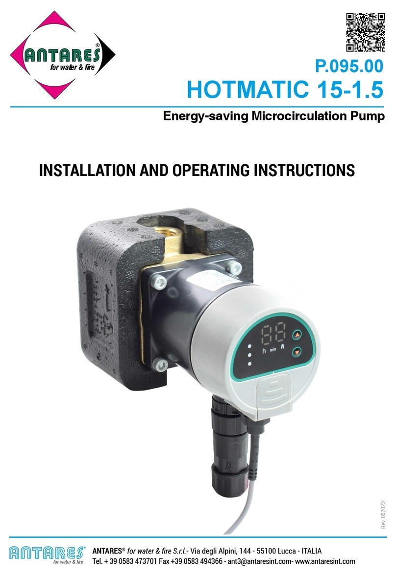
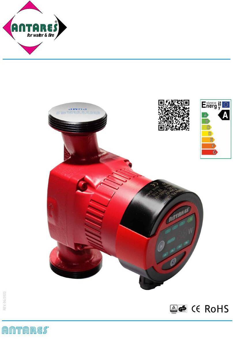
Antares P.023 Quick guide

MODULEX SOLAR UPMS
CONNECT THE EARTH ROD BEFORE THE POWER SUPPLY
DO NOT TOUCH THE PUMP WHILEST FUNCTIONING
DO NOT FUNCTION THE PUMP WITHOUT WATER
Intelligent frequency conversion circulation pump
INSTALLATION AND INSTRUCTION MANUAL
Rev. 032023
EEI≤0,21
for water & fire
ANTARES®for water & fire S.r.l.- Via degli Alpini, 144 - 55100 Lucca - ITALIA
P.023

P.064
89
1
2
3
57
6
89
FIG. 1
FIG. 3
FIG. 6
FIG. 2
FIG. 4
FIG. 5
FIG.7
Yellow: PWM output (from pump)
Red:PWM input (from controller)
Black: Earth cable (GND)
Power cable: 230 Vac
Controller cable PWM
Brown: (PH) Phase
Yellow / Green: Earth
Blue: (N) Neutral
YES
Brown
Yellow
Blue
Rosso
Giallo
Nero
NO
EN 2
EN

MODULEX SOLAR UPMS
1 - Introduction - page 5
2 - Profile and dimensions - page 5
2.1 - Instructions for defining the model - page 5
2.2 - Models and reference codes - page 5
2.3 - Technical data - page 6
2.4 - Dimensions - page 6
3 - Precautions - page 7
4 - Use and installation - page 8
4.1 - Pumped liquids - page 8
4.2 - Liquid temperature and room temperature - page 8
4.3 - Installation - page 9
4.4 - Control panel positions - page 10
4.5 - Electrical connection - page 11
4.6 - Cable connection -page 11
4.6.1 - Power cable connection - page 11
4.6.2 - Power cable connection when replacing existing faulty circulators - page 11
4.6.3 - PWM Controller cable connection - page 12
4.6.4 - PWM Controller cable connection when replacing existing faulty circulators - page 12
5 - Instructions for use - page 13
5.1 - The control panel - page 13
5.2 - Performance curves - page 13
5.3 - Adjustment mode with reference to the LED lights - page 14
5.4 - Adjustment modes and functions - page 15
5.4.1 - PWM2 input signal for solar systems - page 16
5.4.2 - PWM1 input signal for heating systems - page 17
5.4.3 - PWM signal - Technical data - page 18
5.4.4 - PWM feedback signal - page 18
5.4 - Additional functions - page 19
5.5.1 - Vent function - page 19
5.5.2 - PWM signal - Manual release function after long periods of absence - page 19
6 - Troubleshooting - page 20
Overview of components Fig. 1 e Fig. 2
Pump body with threaded connections
Wet rotor motor
Body fixing screws
Electronic control board
Pump identification plate
Control button for pump setting
Operation LED lights: control mode selected/fault
Connecting the PWM control cable
230 Vac mains power supply: connection of the 3-pole plug
1
2
3
4
5
6
7
8
9
INDEX
3 EN
EN

MODULEX SOLAR UPMS
Warning
●This product is not intended for the public, but for professionally
specialized companies.
●Read the instructions carefully before installation and use.
●The pump must be reliably grounded and connected to a differential
disconnector.
●It is strictly forbidden to touch the electric pump whilst functioning.
Warning for Children
●It is strictly forbidden for children, or vulnerable adults, the use of
this product without the supervision of a qualified person.
Electrical warning
●The power supply system may only be used when it is in compliance
with safety rules according to the protection measures specified by
the regulations in force in the Country.
Pressure Warning
●The pumping system must be able to withstand the maximum
pressure of the pump.
Notice regarding the change
●ANTARES declines all responsibility in case of any tampering with
the electric pump or its drive beyond the operating conditions by
the User.
Thank you very much for choosing ANTARES products. Please read the instructions before
installation and use and store them with care.
EN 4
EN

MODULEX SOLAR UPMS
The ANTARES MODULEX SOLAR UPMS circulation pump is an intelligent frequency conversion
circulator with integrated electronic differential pressure control, with the possibility of setting the
regulation module and the head (differential pressure). The differential pressure is controlled by
the pump numbers of revolutions. The motor stator is fully shielded and the rotating parts are
immersed in clean water, playing an important role in cooling and in lubrication whilst functioning.
The shielding sleeve of the electric pump adopts a thin-walled structure to completely shield the
internal stator from water in the engine; the traditional mechanical seal structure is eliminated and
the problem of water leakage of the conventional pump is solved. The rotating parts consist of
ceramic bearings and ceramic rotating shafts, wear resistant and lubricated with clean water, which
cool the engine and reduce its noise. The pump will not overload during full operation performance.
It can be generally maintenance free as long as used correctly.
1 - Introduction
2 - Profile and dimensions
2.1 - Instructions for defining the model
2.2 - Models and reference codes
Length from pump inlet to outlet (mm)
Nominal inlet and outlet diameters (mm)
Pump model
Max head(m)
UPMS 25
-80-130
Art. code Model
Inlet/outlet
mm
Thread
Ø
Max
Flow
m³/h
Head
m
Voltage
Vac
Frequency
Hz
Power
W
Current
A
Ø
H
P.023.89 UPMS 15-80-130 15 130 1" M. 2.9 1-8 220-240 50-60 65 0.65
P.023.80 UPMS 25-80-130 25 130 1 1/2" M. 3.4
5 EN
EN

MODULEX SOLAR UPMS
Supply Voltage 220-240 V, 50/60 Hz
Motor protection Does not require any external protection
Protection class IP44
Insulation class F
Relative room humidity Max 95%
Pressure Max. 1.0 MPA, 10 bar
Suction inlet pressure Liquid
temperature
≤75°C
Min. inlet
pressure
0.05 bar,
0.005MPa
+90°C 0.28 bar,
0.0285MPa
+110°C 1.08 bar,
0.108MPa
Emc Standard GB 4343,2 GB 4343,2 GB 17625,1 GB 17625,2
Room temperature 0°C - 40°C
Surface temperature + 125°C
Liquid temperature + 2°C ~ + 110°C
Liquid Water or Water + Glycol (≤50%)
Model
Size (mm)
L1 L2 L3 H1 H2 H3 Thread
Ø
UPMS15-XX-130
93 126 86 114 130 62
1" M.
UPMS25-XX-130 1 1/2" M.
2.3 - Technical data
2.4 - Dimensions
H1
L1
L2
H2
L3
H3
Ø
EN 6
EN

MODULEX SOLAR UPMS
3 - Precautions
3.1. - The power supply voltage of the electric pump is single-phase 220-240V and the frequency
is 50/60Hz.
3.2. - Make sure that the pipe system is firmly connected before installation and check that
impurities, welding scraps and waste have been removed from inside the pipes. Before
installation in an old system, wash it to remove any sludge present with crystallization of
salts and substances present in the circulating liquid.
3.3. - Make sure the pump is in a dry and ventilated environment to avoid short circuits due to
moisture or splashes in the body and ensure its accessibility for service and replacement.
3.4. - For outdoor installations, provide protection to prevent splashing. Warning: do not install in
the bathroom to prevent steam, water or moisture from entering the electrical box
3.5. - It is highly recommended to install shut-off valves before and after the pump for the next
service and maintenance of the pump.
3.6. - After completing the installation of the pump, connect the power supply as a test and set the
speed adjustment setting to the maximum level to verify that it is starting properly.
NOTE: the test run time cannot be longer then 10 seconds to avoid wearing the life-span of
pads.
3.7. - Do not touch the pump and/or the pipes when supplying water to the heating system to
avoid getting burned.
3.8. - The power supply must be strictly earthed.
3.9. - Safety warnings concerning the pump must be observed during pump operation
to avoid any accident.
3.10. - The power supply must be disconnected before positioning the pump and/or before any
electrical action to the pump to avoid accidents.
3.11. - Check the pump regularly and replace it promptly in case of damage.
3.12. -
The power supply cable may only be replaced with matching cables or specific components.
3.13. - In winter, when the room temperature is below 0°C, the water in the system must be
completely drained, if it is not in use.
3.14. - It is not possible to refill the system frequently with non-distilled water to avoid
sludge formation over time.
CONNECT THE EARTH ROD BEFORE CONNECTING THE POWER SUPPLY
DO NOT TOUCH THE PUMP WHILEST FUNCTIONING
DO NOT FUNCTION THE PUMP WITHOUT WATER
7 EN
EN

MODULEX SOLAR UPMS
Liquid temperature (t1) °C 2-110
Environment temperature (t2) °C 0-40
4.1- Pumped liquids
Clean liquids, not aggressive and not
explosive, not containing solid particles,
fibers or mineral oils.
The PH is 6,5-, 5.
4 - Use and installation 4.2 - Liquid temperature and room
temperature
In order to avoid noises produced by gas
and possible damage to the pump bearings,
the minimum pressure must be maintained
on the pump suction pipe in relation to the
temperature as per the related values below.
Max. pressure:
1.0 MPa (10 bar)
Liquid
temperature 85° C 90° C 110° C
Suction pressure 0.5 m 2.8 m 11.0 m
0.049 bar 0.27 bar 1.08 bar
Do not touch the surface
of the control box to avoid
burning when the pump is
functioning.
M
a
x
1
.0
M
Liquid temperature (t1)
Room temperature (t2)
L
i
qu
id tem
pe
r
R
oom tempera
t
EN 8
EN

MODULEX SOLAR UPMS
Step 1 Step 2 Step 3
4.3 - Installation
The motor shaft must be kept in horizontal direction during installation, the direction of liquid flow
in the pipe must be the same as the arrow marked on the pump body.
Correct installation position of the motor
Incorrect position
n
c
9 EN
EN

MODULEX SOLAR UPMS
The following operations may only be performed by qualified personnel
4.4 - Control panel positions (Fig. 1 ref. 4)
High temperature
1 - Installation direction preview
4 - Remove hexagonal bolts with a hex key 5 - Adjust in the desired direction,
lock the hexagonal bolts
6 - Open the valves, which must remain open
once the power is on
2 - Disconnect power supply before
adjustment
3 - Drain the liquid from the system and close
the valves
Warning: The pumped liquid can be at a high temperature and high pressure. Before
removing the hexagon socket bolts, drain the hot water from the system and close
the shut-off valves on both sides of the electric pump.
High temperature
H
i
g
H
i
gh
te
m
EN 10
EN

MODULEX SOLAR UPMS
4.5 - Electrical connection - Fig. 3-4-5
4.6 - Cable connection
1 - Installation position 2 - Point the plugs toward the control
box socket and insert them
Disconnect the system power supply. Connect the
wire of the supplied connecting cable by observing the
arrangement of the terminals and their reference color.
Make sure that the grounding connection (yellow/green)
is effective. Connect the power connector to the socket of
the pump control box (Fig. 3 - 4 and 5).
Cut with scissors
Shorten the cable coming from
electrical box of the boiler so that the
length is adequate and strip the ends of
the wires
●If The socket of the new circulator does not match the plug of the old one, put an electric coversion adapter on the
plug of the old cable and on the plug of the new circulator. See the adapters in the ANTARES catalogue of sockets for
Grundfos (our art. P.160.01) circulators or Wilo (our art. P.161.01).
OTHERWISE
●Cut off the connector end (plug) of the circulator to be replaced, shorten the cable coming from the electrical box of the
boiler so that it is of adequate length and strip the wires of the cable to connect them to the cable of the new connector
through terminals (see figure below):
Note: Make sure that the power cable does not come into contact with neither the pipes nor with the pump.
3 - Completed assembly
4.6.1 - Power cable connection
4.6.2 - Power cable connection when replacing existing faulty circulators with a different
connector
Electrical
connection
Connection
signal PWM
Cable connection:
1 Brown: L (Phase)
2 Blue: N (Neutral)
3 Yellow/Green: PE ( )
123
n
pu
mp.
Cu
t
with
s
ci
ss
or
s
Sh
h
bl
i
f
Brown
Brown
Yellow - Green
Blue
Blue
El
ec
tr
ic
al
co
nn
ec
ti
on
Co
nn
ec
ti
on
s
i
g
nal PWM
11 EN
EN

MODULEX SOLAR UPMS
4.6.3 - PWM controller cable connection - Fig. 3-5
4.6.4 - Cable connection of the PWM Controller when replacing existing faulty circulators
with different connector or without PWM connection
Disconnect the power supply. Make the wite connections of the supplied connecting cable by observing the arrangement of
the terminals and wire reference color for connection.
Connect the PWM connector plug to the socket of the pump control box (Fig. 3 and 5).
Connect the system voltage.
ATTENTION: connecting the mains voltage (230 Vac) to the communication pins (PWM) destroys the product. On the PWM
input, the maximum voltage level corresponds to 24 V pulsed input voltage.
●If the boiler does not have the connection to the PWM controller, it is not necessary to make the connection, but select
the circulator in the most suitable working function or in the Autoadapt position. The circulator will automatically
adapt to the system requirements.
●If the socket of the new circulator does not match the plug of the old
one, insert an electrical conversion adapter on the plug of the old
cable and that of the new circulator. See in the ANTARES catalogue
gli socket adapters for Grundfos circulators (our art. P.163.01) or Wilo
(our art. P.164.01).
OTHERWISE
●Cut the end of the connector (plug) of the circulator to be replaced, shorten the cable coming from the electrical box
of the boiler so that it is of adequate length and strip the wires of the cable to connect them to the cable of the new
connector through the wiring terminals (see figure below):
Cable connection:
1) Red: PWM input (from controller)
2) Yellow: PWM output (from pump)
3) Black: (GDN) earth cable
Red
Black
Yellow
123
Brown
New pump cable
Blue
Red
Black
Yellow
Black
Shorten the cable coming from
electrical box of the boiler so that
the length is adequate and strip
the ends of the wires
Example combination cable wires
PWM
*If the PWM cable from the
boiler has a 2-wire connection,
make the following connection:
Red - Brown
Black - Blue
Yellow - disconnected
For
substitution
Wilo and
Grundfos
o
m
i
n
g
f
rom
bo
il
e
r
so
t
h
at
a
te and strip
s
Cut with scissors
Red
Brown
Blue
Black
EN 12
EN

MODULEX SOLAR UPMS
5.2- Performance curves
5.1 - Control panel
5 - Instructions for Use
Pump performance symbols:
Possibility to set the control mode and the delivery (differential pressure).
The differential pressure is regulated by the pump speed.
Delivery: 8 mt
Modulex Solar
UPMS xx 80 xx
H (m)
8
7
6
5
4
3
2
1
0
0 0.2 0.4 0.6 0.8 1 1.2 1.4 1.6 1.8 2 2.2 2.4 2.6 2.8 3 3.2 3.4 3.6 3.8 Q(m3/h)
CP III
CP II
CP I
CS I CS II CS III
PP III
PP II
PP I
AUTO
PP= Proportional Pressure
CS= Constant Speed
CP= Constant Pressure
AUTO = Self Adapt – Automatic Control
Led
Button
13 EN
EN

MODULEX SOLAR UPMS
5.3 - Adjustment mode with reference to the LED lights
The pump functionality setting is configured with different display of the LED
lights.
Press number of
times Model Descriptions Display
0 CS III (Factory setting) Constant curve speed III
1 AUTO Automatic adapt mode
2 PP I Proportional pressure
curve speed I
3 PP II Proportional pressure
curve speed II
4 PP III Proportional pressure
curve speed III
5 CP I Constant pressure curve
speed I
6 CP II Constant pressure curve
speed II
7 CP III Constant pressure curve
speed III
8 CS I Constant curve, speed I
9 CS II Constant curve, speed II
10 CS III Constant curve, speed III
11
PWM
Flashing light:
PWM1 (CS3) mode
12 Flashing light:
PWM2 mode
/External control of
motor speed
PP CP AUTO
PP CP AUTO
PP CP AUTO
PP CP AUTO
PP CP AUTO
PP CP AUTO
PP CP AUTO
PP CP AUTO
PP CP AUTO
PP CP AUTO
PP CP AUTO
PP CP AUTO
PP CP AUTO
PP CP AUTO
EN 14
EN

MODULEX SOLAR UPMS
5.4 - Adjustment modes and functions
Variable differential
pressure ∆p-v (I, II, III,)
Constant differential
pressure ∆p-c (I, II, III,)
Number of constant turns
(I, II, III,)
Recommended in case of heating systems with delivery
and return pipes with radiators, for the reduction of flow
noise on thermostatic valves and zone sections.
The pump halves the delivery in case of flow reduction in
the pipeline network (radiators or closed areas). Electrical
energy is saved by adapting the delivery to the required
flow rate and reduced flow speed. Three predefined
characteristic curves including (I, II, III) according to
choice.
Recommended in case of radiant panels (floor systems) or
large pipes and for all applications without variable system
characteristic curves, (e.g. circulation in accumulators or
heaters) and single-pipe heating systems with radiators.
The regulation maintains the set delivery regardless of the
conveyed flow rate.Three predefined characteristic curves
including (I, II, III) according to choice.
Recommended for systems with steady resistance that
require a constant flow rate.
The pump operates in three stages corresponding to
numbers of preset fixed laps (I, II, III).
NOTICE
Factory setting: (PWM2)
Constant speed, constant curve.
CS = Constant Speed
CP = Constant Pressure
PP = Proportional Pressure
15 EN
EN

MODULEX SOLAR UPMS
5.4.1 PWM2 input signal (solar systems)
With a low percentage of PWM signal (duty cycles), a hysteresis prevents the circulation
pump from starting and stopping if the input signal oscillates around the change point.
Without PWM signal percentage, the circulation pump will stop for safety reasons. If a signal
is missing, e.g. due to a break in the cable, the circulator will stop preventing overheating.
PWM (%)
10095151270
min
max
n/1/min
The pump speed is controlled according to the signal PWM input
signal, when connected.
In PWM mode, the rotation speed of the pump is regulated acording
to the input signal (PWM).
If there is no PWM signal or cable is not connected, the pump
operation is controlled by internal logic.
External adjustment via
iPWM signal
PWM = Esternal
adjustment with iPWM
signal
Galvanic isolation
1 4
47PF
47PF
PWM input
PWM output
signal ref
1Ω
1K
PE
N
L
3
3
2
2
2
1
3
1
+5V
4
Electronic control
The "MODULEX SOLAR PUMPS" was created for use in solar systems
using the PWM2 signal but can also be used in heating systems by
setting the PWM1 signal.
H/m
Q/m3/h
PWM
% PWM 1 (% PWM 2)
5 (95%)
15 (85%)
25 (75%)
35 (65%)
45 (55%)
55 (45%)
65 (35%)
75 (25%)
85 (15%)
EN 16
EN

MODULEX SOLAR UPMS
PWM input signal (%) Pump status
0Stop
0<PWM≤7 Standy mode: off
7<PWM≤15 Max speed work phase
12<PWM≤15 Max speed. initial phase
15<PWM≤95 Variable speed: from min. to max.
95<PWM≤100 Maximum speed
5.4.2 PWM1 input signal (heating systems)
At high PWM signal rates (duty cycles), a hysteresis prevents the circulation pump from
starting and stoping if the input signal fluctuates around the change point. At low PWM
signal rates the speed of the circulation pump is high for safety reasons. In the event of
cable breakage in a system with a gas boiler, the circulation pump will continue to run at
maximum speed to transfer heat from the primary heat exchanger.
Speed
PWM input signal (%)
5 10 20 30 40 50 60 70 80 90 100
PWM input signal (%) Pump status
0Switch the pump to non-PWM mode (internal
control)
0<PWM≤5 Maximum speed: max.
5<PWM≤84 Variable speed: from max. to min.
84<PWM≤93 Minimum speed: min.
88<PWM≤93 Hysteresis area: on / off
94<PWM≤100 Standby mode: off
17 EN
EN

MODULEX SOLAR UPMS
Galvanic isolation in the pump YES
PWM frequency input 100 - 5000Hz
High level input voltage UiH 3.3 - 24V
Low level input voltage UiL <0.7V
High input current IH 3.5mA - 10mA
PWM input duty cycle 0-100%
Signal polarity fissa
Signal cable length <3m
Rise / fall time span <T/1000
5.4.3 PWM signal: technical data
T
t
UiH
UiL
5.4.4 - PWM feedback signal (energy consumption)
PWM output
signal (%)
Qualification time
QT (S) Pump information Disqualification
time DT(S) Priority
100 0 Standby by PWM signal (STOP) 0 1
95 0-60 Alarm/Stop/Block Error (locked rotor/dry
run,stop) 0-600 2
90 0-30 Alarm/stop/electrical error (phase
loss/overload, stop) 1-5 3
85 0 Warning (under/over voltage, stop) 0 4
80 0
Warning (160-194V, the pump has low working
efficiency, the power feedback accuracy is
abnormal, but the pump still runs)
05
5-75 0 The pump is running normally, feedback
0—4.5m³/h flow information 07
2 0 Standby, hysteresis point waiting to run 0 6
0 0 PWM signal interruption 0 8
Output frequency 75Hz+/-5%
100
90
80
70
60
50
40
30
20
10
25 50 100 150 200 250 Power [W]
Standby (stop)
Alarm, stop, fault, blocked error
alarm, stop, electrical error
Warning Saturation at 70 W
Slope: 1 W/% PWM
EN 18
EN

MODULEX SOLAR UPMS
5.5 - Additional functions
5.5.1 - Vent function
The vent function of the pump is activated by pressing the button for a long time until the first
three LEDs light up and releasing immediately. The pump will automatically vent.
5.5.2 - Manual release function after long
periods of absence
The manual restart function of the pump is activated by pressing the button for a long time
until all five LEDs light up and releasing immediately. It is indicated, for example, after long
periods of inactivity during the summer period.
19 EN
EN

MODULEX SOLAR UPMS
6 - Troubleshooting
Symptom Probable cause What you can do
Pump does not work
Loose connection on power supply Make sure that the power cord is
securly connected to the cable
Blown fuse Replace the damaged fuse
Damaged capacitator Replace the damaged capacitator
The motor impeller can be
wrapped with fibers or blocked
with other components
Remove fibers and foreign bodies
No PWM signal / Broken PWM
cable
With PWM1 the pump will
automatically switch to CS III
With PWM2 change the pump
setting from PWM to CS
Noise inside the system or inside
the pump body
Impurities inside the pump Disassemble the pump and clean
from impurities
The set flow rate is too high Switch to a lower speed
Air or gas in the system or in the
pump body Discharge air or gas
The pump works but does not
generate pressure
Suction valve is closed Open the valve
Air or gas inside the pipes or the
pump
Open the valve to run the pump
and loosen the fittings to allow air
and gas to escape.
Type of protection Display
Locked rotor protection
Overload and undervoltage protection
Open phase protection
Overload protection
PP CP AUTO
PP CP AUTO
PP CP AUTO
PP CP AUTO
EN 20
EN
This manual suits for next models
4
Table of contents
Other Antares Water Pump manuals
Popular Water Pump manuals by other brands

Bosworth
Bosworth Guzzler G2-0501N Operator's manual

DYI SHENG
DYI SHENG DS03-A operating manual

Neptun
Neptun Classic NCTP-O 300i operating instructions

MATALA WATER TECHNOLOGY
MATALA WATER TECHNOLOGY G-1900 Instruction and maintenance manual

Ribimex
Ribimex Ribiland PRPVC751V User and maintenance manual

AquaCare
AquaCare Turbo Chalk Reactor instruction manual