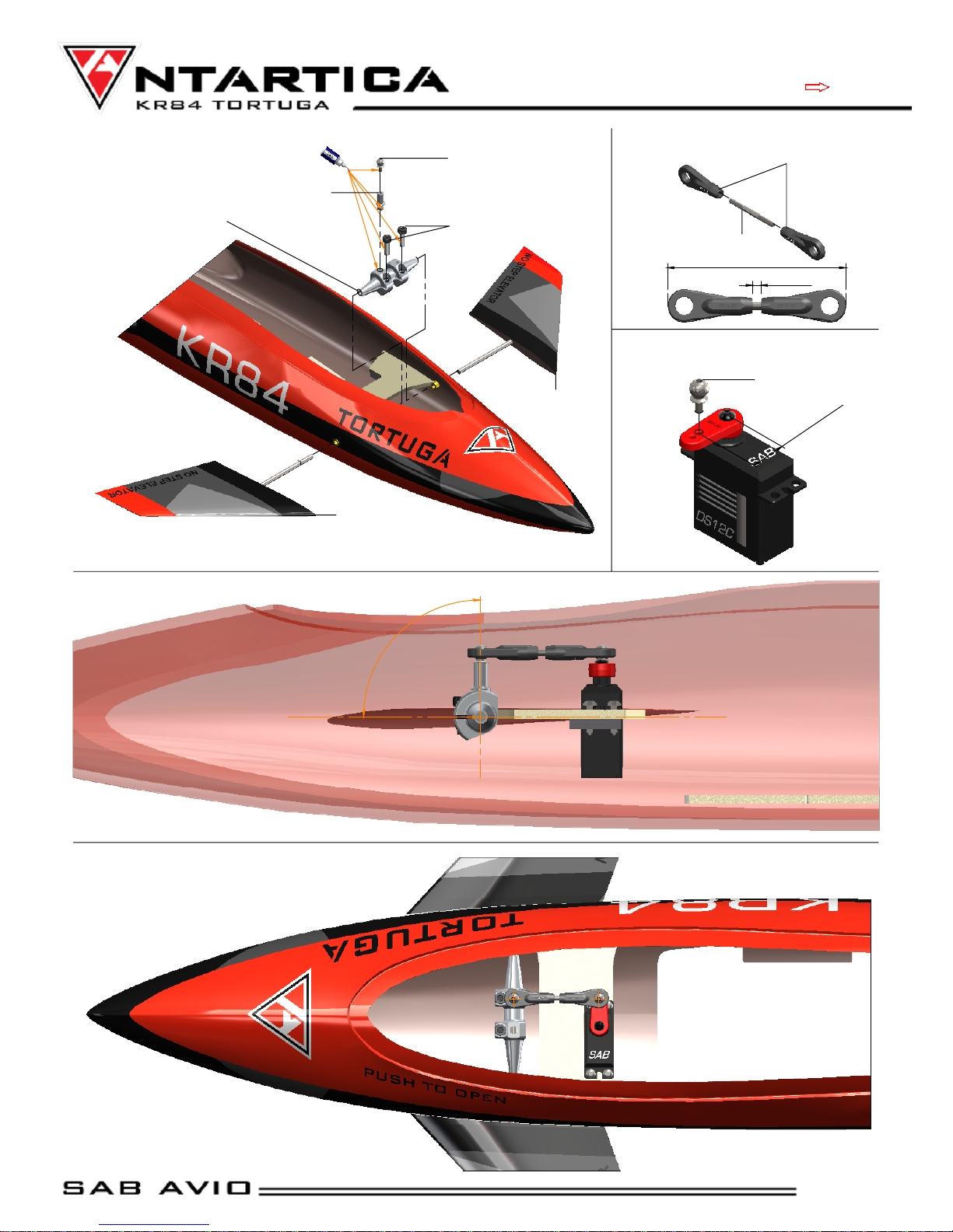
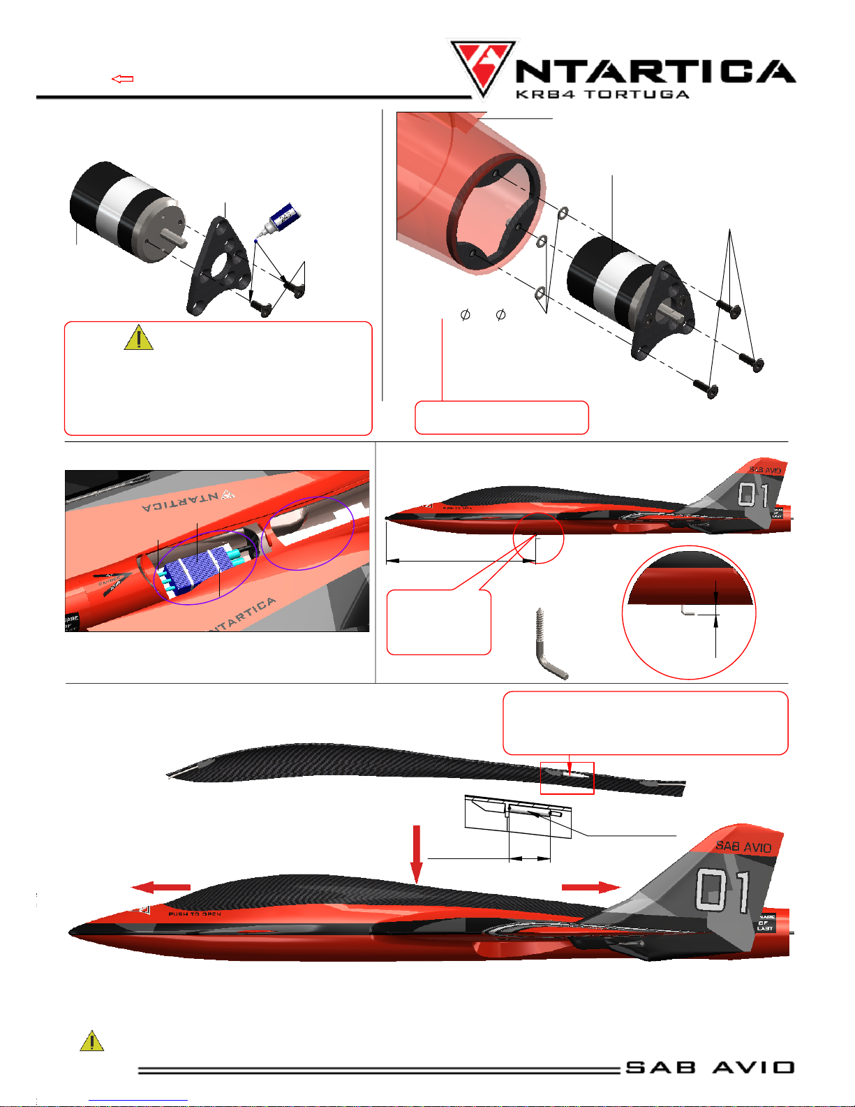
Antartica KR84 Tortuga User manual


16 cm
81 cm
24 cm
84 cm
SPECIFICATIONS
This is the semi-scale 1/8 model of the KR84 Tortuga ROBODRONE Version that fought in the Kemp battle of 513
2
Set up suggested:
6S -- 2600/3200 mAh
2200 kV motor inrunner, 28-36mm
120A ESC
Max Motor Size
*36mm diameter electric motor, 150 grams
Battery Compartment: 55x45x200 mm
Please read this user manual carefully, it contains instructions for the correct assembly of the model.
Please refer to the web site www.sabavio.com for updates and other important information.
It is extremely important that you take a moment to register your airplane with us. This is the only way to ensure that you are
properly informed about changes to your kit, such as upgrades, retrofits and other important developments. SAB Avio cannot
be held responsible for issues arising with your model and will not provide support unless you register your serial number.
Thank you for your purchase, we hope you enjoy your new Tortuga!
SAB Avio Team
VERY IMPORTANT
In the Manual bag you will find a product card with your serial number. Please take a moment to
register your kit online via our website:
www.sabavio.com
Wing Span : 84 cm
Wing Area : 2400 cm
Maximum Lenght : 81 cm
RTF Weight : 1.5 Kg
Maximum Total Weight : 1.7 Kg
Page 1
Chapter 1,
Specifications

Use Thread Locker
Medium Strength
( SAB HA116-S)
Sand and fit
where necessary
Mill
IMPORTANT NOTES
*This radio controlled airplane is not a toy.
*This radio controlled airplane can be very dangerous.
*This radio controlled airplane is a technically complex device which has to be built and handled very carefully.
*This radio controlled airplane must be built following these instructions. This manual provides the necessary information to correctly
assemble the model. It is necessary to carefully follow all the instructions.
*Inexperienced pilots must be monitored by expert pilots.
*All operators must wear safety glasses and take appropriate safety precautions.
*A radio controlled airplane must only be used in open spaces without obstacles, and far enough from people to minimize the possibility
of accidents or of injury to property or persons.
*A radio controlled airplane can behave in an unexpected manner, causing loss of control of the model, making it very dangerous.
*Lack of care with assembly or maintenance can result in an unreliable and dangerous model.
*Neither SAB Avio nor its agents have any control over the assembly, maintenance and use of this product. Therefore, no
responsibility can be traced back to the manufacturer. You hereby agree to release SAB Avio from any responsibility or
liability arising from the use of this product.
SAFETY GUIDELINES
*Fly only in areas dedicated to the use of model.
*Follow all control procedures for the radio frequency system.
*It is necessary that you know your radio system well. Check all functions of the transmitter before every flight.
*The propeller of the model rotate at a very high speed; be aware of the danger they pose and the damage they may cause.
*Never fly in the vicinity of other people.
DAMAGE LIMITS
SAB AVIO SHALL NOT BE LIABLE FOR SPECIAL, INDIRECT OR CONSEQUENTIAL DAMAGES, LOSS OF PROFITS OR PRODUCTION OR COMMERCIAL
LOSS IN ANY WAY CONNECTED WITH THE PRODUCT, WHETHER SUCH CLAIM IS BASED IN CONTRACT, WARRANTY, NEGLIGENCE, OR STRICT
LIABILITY. Further, in no event shall the liability of SAB Avio exceed the individual price of the Product on which liability is asserted. As SAB Avio
has no control over use, setup, final assembly, modification or misuse, no liability shall be assumed nor accepted for any resulting damage or
injury. By the act of use, setup or assembly the user accepts all resulting liability. If you as the Purchaser or user are not prepared to accept the
liability associated with the use of this Product, you are advised to return this Product immediately in new and unused condition to the place of
purchase.
LIMITED WARRANTY.
SAB Avio reserves the right to change or modify this warranty without notice and disclaims all other warranties, express or implied.
(a)
This warranty is limited to the original Purchaser (“Purchaser”) and is not transferable. REPLACEMENT AS PROVIDED UNDER THIS WARRANTY
IS THE EXCLUSIVE REMEDY OF THE PURCHASER This warranty covers only those Products purchased from an authorized SAB Avio dealer. Third
party transactions are not covered by this warranty. Proof of purchase is required for warranty claims.
(b)
Limitations- SAB AVIO MAKES NO WARRANTY OR REPRESENTATION, EXPRESS OR IMPLIED, ABOUT NONIFRINGEMENT, MERCHANTABILITY OR
FITNESS FOR A PARTICULAR PURPOSE OF THE PRODUCT. THE PURCHASER ACKNOWLEDGES THAT THEY ALONE HAVE DETERMINED THAT THE
PRODUCT WILL SUITABLY MEET THE REQUIREMENTS OF THE PURCHASER’S INTENDED USE.
(c)
Purchaser Remedy- SAB Avio’s sole obligation hereunder shall be that SAB Avio will, at its option, replace any Product determined by SAB
Avio to be defective In the event of a defect, this is the Purchaser’s exclusive remedy. Replacement decisions are at the sole discretion of SAB
Avio. This warranty does not cover cosmetic damage or damage due to acts of God, accident, misuse, abuse, negligence, commercial use, or
modification of or to any part of the Product. This warranty does not cover damage due to improper installation, operation, maintenance or
attempted repair by anyone
NOTES FOR ASSEMBLY
Please refer to this manual for assembly instructions for this model. Follow the order of assembly indicated. The instructions are divided into
chapters, which are structured in a way that each step is based on the work done in the previous step. Changing the order of assembly may
result in additional or unnecessary steps.
Use thread lockers and retaining compounds as indicated. In general, each bolt or screw that engages with a metal part requires thread lock.
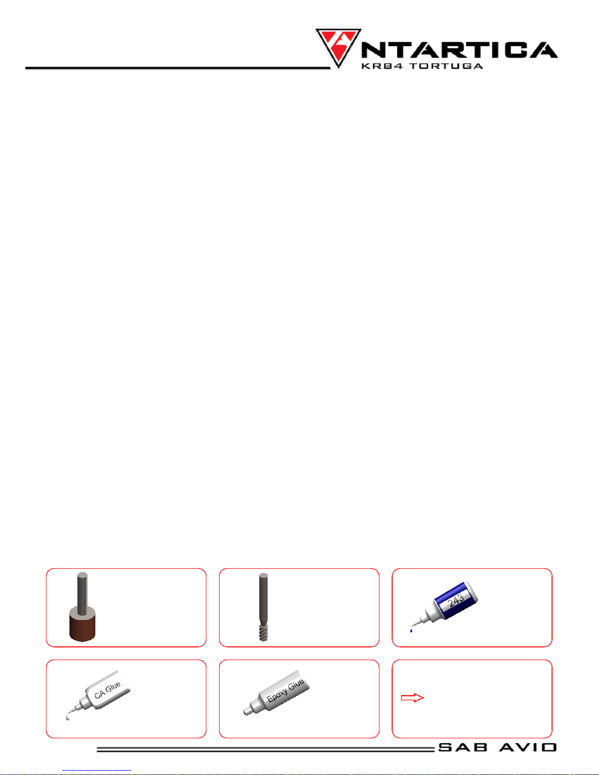
It is necessary to pay attention to the symbols listed below:
Use CA Glue
Use Epoxy Glue
Indicates that for
this assembly phase
you need materials
that are in bag xx.
Bag xx
Page 2
Chapter 2, Important Notes

ADDITIONAL COMPONENTS REQUIRED
Electric Motor: Maximum diameter 40mm.
Speed Controller (ESC): Suitable for own configuration.
Batteries.
4/6 channel radio control system
Radio power system.
1 Canard servo ( Micro servo size 23mm ).
2 Wing servos, maximum thickness 10mm.
3 Servo Extension Cords, if necessary.
1 Propeller adaptor.
1 Propeller.
TOOLS AND ADHESIVES
Drill with drill bits 2, 3, 4mm.
Small milling cutter for drill.
Generic pliers.
Hexagonal driver, size 1.5, 2, 2.5, 3 mm.
Cyano-acrylate glue.
Epoxy glue.
Medium threadlocker (eg. Loctite 243).
Soldering equipment (for electric wiring).
Inside the box
Inside the Box
Fuselage
Canopy
Bags
Manual
The assembly process is described in the following chapters. Each chapter provides you with the bag number you will need for that
chapter. The information is printed in a red box in the upper right corner of the page at the beginning of every chapter.
Manual
Fuselage
Canopy
Main Box
Bags
Page 3
Chapter 4 - In the box

2°
2mm
3mm
80°
140°
Motor Mount Assembly
Inclinate about 2° the motor mount. It is possible to set the
right inclination of motor shaft just adding washers between
Motor Frame and Motor Mount.
Motor Frame
(S0045-S)
Tortuga Fuselage
BAG 1
TOP
Motor Flanged Option
S0045 S0046 S0034 S0035
28mm Motor 36mm Motor
BAG 5.1 BAG 5.1BAG 1.1 BAG 1.2
Page 4
Chapter 5, Propulsion System Assembly

2mm
Approx 43mm
FF
90°
9-10mm
Canard Mechanics Assembly
Canard Servo Machenics
(S0021-S)
Spacer
(S0021-S)
Uniball M2
(S0039-S)
Socket Head Cap M3x10mm
(S0039-S)
Canard
(S0033-S)
Canard Servo Assembly
Micro servo size : 23mm
Servo Rod Assembly
(S0039-S)
Plastic Ball Linkage M2
Set Screw M2x22mm
Uniball M2
Canard
(S0033-S)
BAG 2
Page 5
Chapter 6, Canard System Assembly

Approx 88mm
2.5mm
3.5mm
2.5mm
Approx 10-12mm
Aileron Servo Linkage Assembly ...x2
(S0039-S)
Servo
Clevis
Linkage Rod M2x56mm
Plastic Ball Linkage
Servo Mount
(S0036-S)
Servo
Note:
Linkage Rod H0237-S has left thread and right thread.
It permits linkage adjusting without disconnecting the
plastic ball links by inserting a small tool through the
rod hole and turning it.
Note:
Use epoxy to glue in the servo mount. Check the suggested
position in according to the size of your servo.
Socket Self Tapping
Screw M2.9x6.5mm.
Uniball M2
Nut M2
BAG 3
Aileron Servo Mount Assembly ...x2
Aileron Servo Assembly ...x2
Aileron Servo Linkage
Assembly
Aileron Servo
Wing Servo 30x30x10
Page 6
Chapter 7, Aileron Servo Assembly

90°
Rudder Positioning
Rigid Vertical Rudder
(S0031-S)
Aileron Servo Cover Positioning
Cover Stick
(HC525-S)
Aileron Servo Cover
(S0037-S)
Suggest:
To avoid dirtying the
joining area, it is recommended
to protect it with paper tape
during the gluing operation.
It is also recommended to use
sandpaper to prepare the
surface in the gluing area.
NOTE:
BAG 4
Page 7
Chapter 8 - Rudder Positioning

CC EE
B
300mm
A
8mm
Approx 28mm
Plastic tube 2,5x4
Canopy positioning
1. Put front spring into front holder and push forward the canopy in order to permit rear spring positioning.
2. Push down the canopy on the fuselage.
3. Put rear spring into rear holder and put the end of the canopy under the fuselage.
1
2
3
Canopy springs positioning
ESC frame Positioning
The ESC can be installed in the 2 positions shown.
In according with your setup choose the best position to
get a correct CG. Use Zip-tie to keep ESC in position.
Motor Installation
Find better holes for motor coupling.
Drill if necessary to facilitate installation.
Motor Assembled
ESC Frame
ESC
Motor Mount
(S0046-S)
Flat Head Cap
Screws M3x10mm
[HC135-S]
Main Fuselage Assembled
Motor
Washer
3,3x
6x0,5mm
NOTE:
USE shim to adjust
motor angle if necessary
Zip-tie
NOTE:
To define the end-movement of the canopy,
cut the plastic tube to the optimal length
(about 28 mm), verifying the perfect positioning.
Add a small drop of CA glue to keep tube in position.
Hook for Launch
Hook
BAG 5
NOTE:
It is recommended to use an aluminum heatsink
for the motor.
Note:
Drill in this point
( 1mm diameter )
Be carefull when you put on or take off carbon canopy to avoid scratches on the paint.
Flat Head
Cap M3x8mm
[HC134-S]
Before assembling the screws to the motor, check if the
length of the M3x8 screws is compatible with the motor.
If they are too long they can damage the motor inside
and therefore, screws must be cut off.
WARNING
Page 8
Chapter 8, Canopy Lock System Assembly

CG
Center of Gravity Position
Set the Battery in order to get the correct position of the Center of Gravity (CG) shown in figure 1. The right CG position allow to fly with
an excellent stability. If it is necessary add weight (lead) in the nose.
Radio settings
Mix the canard rotation with elevator deflection. When elevator go up, the canard should increase its incidence as in figure 2.
Set minimum two flight conditions, indicated in table below.
Radio test and pre flight check
Before try the airplane, check the radio and check the reception on distance. Check the movement of each parts. Before any flight
check CG position and be sure the battery is well fixed.
The size of the propeller depends on the setup used. With the recommended setup, we suggest starting with a 5x5 propeller
Verify the current absorption of your motor / propeller setup.
First flight
The propeller of the model rotate at a very high speed; be aware of the danger they
pose and the damage they may cause.
Launch the TORTUGA against the wind with motor at maximum with radio in low speed condition.
We advise catapult-launcing for the first flights.
The launch angle must be minimum 30° as in figure 3.
~ 30
Battery
Battery Strap
205mm L 16mm W
(HA044-S)
Velcro Tape 36x100mm
(HA045-S)
BAG 6
Low Speed Condition
High Speed
Condition
Deflection
Exponential
Deflection
Exponential
Ailerons
± 12 mm
50%
± 6 mm
60%
Elevator
± 12 mm
50%
± 6 mm
60%
Canard
± 8 mm
-
± 3 mm
Page 9
Chapter 9, First Flight

A
3
5
4
4
6
6
16
7
19
12
22
10
25
8
14
15
11
13
2
12
12
1
21
11
18
20
9
17
24
23
14
DETAIL A
A
POS
Code
Name
Specification
Quantity
1
S0021
Canard Collar
Aluminum
1
2
S0022
Spacer
Aluminum
1
3
S0030
Fuselage
1
4
S0031
Rigid Vertical Rudder
2
5
S0032
Canopy
Carbon Fiber
1
6
S0033
Canard
Carbon Fiber
2
7
S0045
Motor Frame
Carbon Fiber
1
8
S0046
Motor Mount
Carbon Fiber
1
9
S0036
Servo Mount
30x35.5mm
2
10
S0037
Aileron Servo Cover
Carbon Fiber
2
11
H0403
Plastic Ball Link
Plastic
4
POS
Code
Name
Specification
Quantity
12
H0538
Uniball
3
13
H0561
Set Screw
M2x22mm
1
14
Socket Self Tapping Screw
M2.2x10mm
2
15
HC056
Socket Head Cap
M3x10mm
2
16
HC135
Flat Head Cap
M3x10mm
3
17
HC180
Washer
3.3x 6x0.5
3
18
HC197
Nut
M2
2
19
HC206
Nylon Nut
M3
3
20
HC244
Linkage Rod M2x56mm
M2x56mm
2
21
HC521
Socket Self Tapping Screws
M2.9x6.5mm
6
22
HC522
Clevis
M2.5
2
23
HC523
Plastic Tube
2.5x
4 1
24
HC524
Hook
1
25
HC525
Cover Stick
Carbon Fiber
4
Page 10
Chapter 10, Exploded View

Rigid Vertical Rudder
[S0031-S]
Canopy
[S0032-S]
Aileron Servo Cover
[S0037-S]
Canard
[S0033-S]
Motor Mount ( 36mm Motor Diameter)
[S0035-S]
Servo Supports
[S0036-S]
- 2 x Rigid Vertical Rudder.
-
1 x Canopy.
-
1 x Plastic tube
2,5x
4x40mm.
- 2 x Aileron Servo Cover.
- 4 x Cover Stick.
- 2 x Canard.
-
1 x Motor Frame
.
- 1 x Motor Mount.
- 3 x Flat Head Cap Screws M3x10mm.
- 3 x Nylon Nut M3.
- 3 x Washer
3,3x
6x0,5mm.
- 2 x Servo Support 30x35,5mm.
- 2 x Aileron Horn.
Page 11
Chapter 11, Spare Parts

- 1 x Canard Servo Mecanics.
- 2 x Linkage Ball M2.
- 2 x Uniball M2.
- 2 x Socket Head Cap M3x10mm.
- 1 x Set screw M2x22mm.
- 1 x Spacer.
Canard Servo Mechanics
[S0021-S]
Hardware
[S0039-S]
- 4 x Plastic Ball Linkage.
- 4 x Uniball M2.
- 3 x Socket Head Cap Screw M3x10mm.
- 3 x Washer 3,3x 6x0,5mm.
- 3 x Metric Hex Nylon Nut M3.
- 2 x Linkage Rod M2x56mm.
- 6 x Socket Self Tapping Screw M2.9x6.5mm.
- 2 x Clevis.
- 2 x Metric Hex Nut M2.
- 1 x Hook.
- 1 x Plastic Tube
2.5x
4.
- 2 x Socket Head Cap M3x8mm.
- 1 x Set screw M2x22mm.
Motor Mount ( 28mm Motor Diameter)
[S0045-S]
-
1 x Motor Frame
.
- 1 x Motor Mount.
- 3 x Flat Head Cap Screws M3x10mm.
- 3 x Nylon Nut M3.
- 3 x Washer
3,3x
6x0,5mm.
Page 12
Chapter 11, Spare Parts


KEMP BATTLE
NAME: KR84 TORTUGA
VERSION: Robodrone
ROLE: Reconnaissance and attack
MANUFACTURER: Kruger Industries
NAME: K175 DRAKE
VERSION: Robodrone
ROLE: Multirole fighter
MANUFACTURER: Kruger Industries
NAME: M169 HAVOK
VERSION: Robodrone
ROLE: Multirole fighter
MANUFACTURER: Mc Murdo Industries
Year 513: THE BATTLE OF KEMP
After months of bankruptcy negotiations, the state of Newland organized a surprise attack with the purpose
of destroying the military bases of Syowa, Progress and Davis and regain control of the self-proclaimed state
of Stockland.
The attack was scheduled for June 21st, 513, the first day of winter, which later became famous as "dark day".
Thanks to intelligence acquired by the secret service of New Antartica, the rebel legion had prepared itself ahead of
the attack and this led to the historic sky battle of Kemp.
On June 21st, Newland forces comprised of Robodrone Tortuga and Drake Bombers faced the Havok Multirole
Fighter of the rebel brigade of Stockland.
The fierce battle caused serious losses to both sides without declaring a real winner.
Huge investments were later made by both parties to increase their arsenal and strengthen their fleet.
SABAVIO.COM
TIPS & TRICKS VIDEOANTARTICA MOVIE
SAB AVIO WEBSITE
Table of contents
Other Antartica Toy manuals
Popular Toy manuals by other brands

Fisher-Price
Fisher-Price W6117 manual

KidKraft
KidKraft Espresso Kitchen 53295 Assembly instructions

Fisher-Price
Fisher-Price COLOR ME GEMZ N1128N1128 instruction sheet

REVELL
REVELL APOLLO SATURN V Assembly manual

SIG
SIG Kougar MARK II SIGRC35 Building and flying instructions

Flying Styro Kit
Flying Styro Kit MESSERSCHMITT BF 110 C Owner's instruction manual