Antti-Teollisuus Oy 6 408099 11-2020
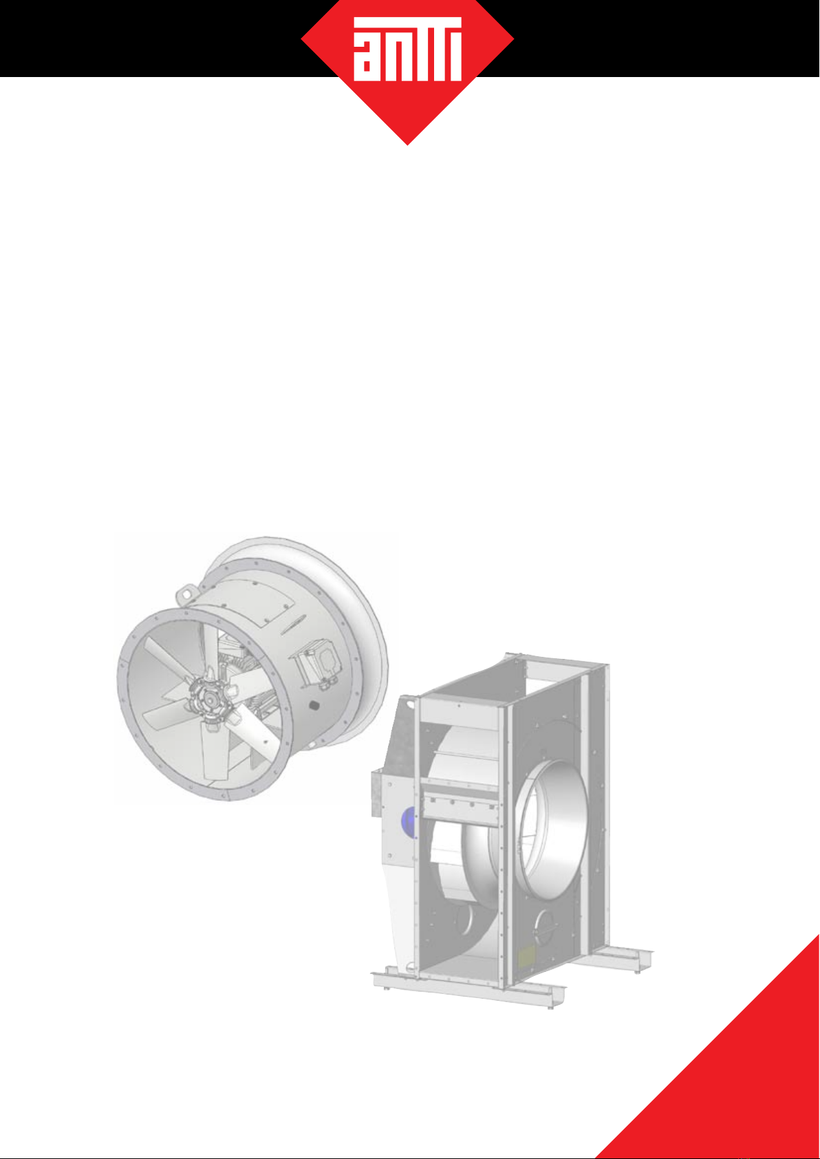
Blower units and axial blowers
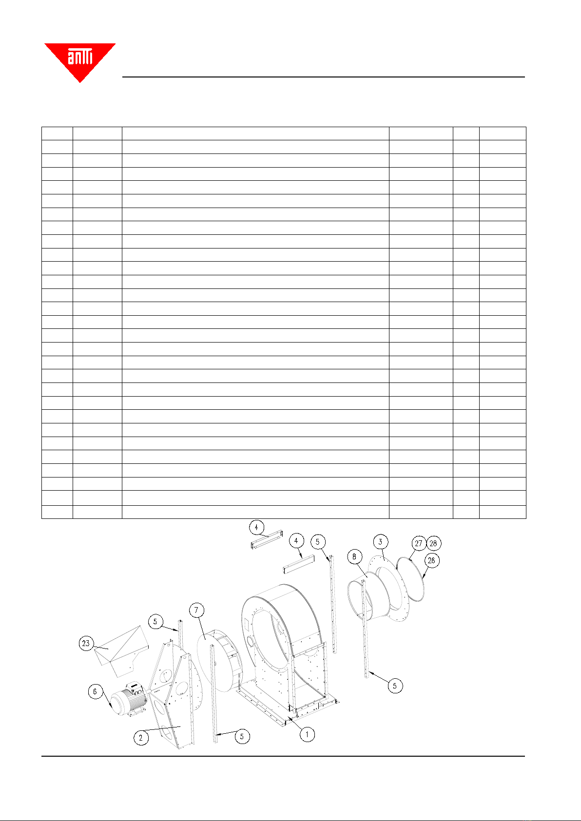
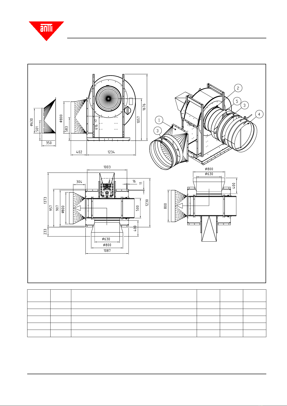
SPARE PARTS DRAWING 15 kW
Part Item Denomination Drawing No. Pcs. Weight
1 A71860 BLOWER A400 SUB-ASSEMBLY A71738-0 1 104,45
2 A71897 BLOWER A400 MOTOR RACK ASSEMBLED A71897-0 1 53,87
3 33407 BLOWER A400 SUCT CH ATTACH ASSY ROUND 33407-0 1 11,42
4 A71140 DR HEATER BLOWER HOUS A400 FRAME SUPP M03 A71140-0 4 1,91
5 A71141 DR HEATER BLOWER HOUS A400 REP K SUPP M03 A71141-0 4 3,90
6 303524 MOTOR 15,00 KW 1500R B3 303524- 1 120,0
7 22476 ROTOR STANDARD B840/167 15KW 22476-B 1 38,90
8 31560 DR HEATER BLOWER A400 SUCT CONE D624/576 31560-A 1 6,43
9 41560 HATCH D170+HOLDER 41560-0 2 0,46
10 117911 PLATE STICKER 25x50 THT-17-434-3 0 1 0,00
11 400342 WASHER PL5 D 52/13 0 4 0,08
12 102573 HEX BOLT M12x50 DIN931 0 4 0,00
13 111560 WASHER ZN M12 ZN DIN 125 0 4 0,00
14 112320 LOCK WASHER M12 (112320) DIN 6798A 0 4 0,00
15 110570 NUT M12 DIN934 0 4 0,00
16 101860 HEX BOLT ZN 8x35 DIN933 0 4 0,00
17 110540 NUT M8 DIN 934 0 120 0,00
18 117774 PLATE STICKER, DANGER FROM ABOVE 0 2 0,00
19 400340 WASHER PL5 D52/17 - 1 0,07
20 112320 LOCK WASHER M12 (112320) DIN 6798A 0 1 0,00
21 103011 HEX BOLT M16x60 DIN931 0 1 0,00
22 117920 PLATE ARROW 117920-0 1 0,00
23 A71172 RAIN COVER PLATE A-400 11/15 KW M03 A71172-C 1 6,48
24 101820 HEX BOLT ZN 8x20 DIN933 0 112 0,00
25 503015 DR HEAT BLOW A400 INTERM SLEEVE D56-11 41301-2 1 0,09
26 504591 AIR DUCT BAND D625 A71000-0 1 0,52
27 104243 BOLT HEX SOCKET 6X70 AM 0 1
28 110530 NUT M6 DIN 934 0 1 0,00
Spare parts drawing, 11 kW and 15 kW