13. 6.
PRODUCT F° C° COOK TIME
BEEF HAMBURGER PATTIES 125 grams (3.3 OZ) 400 205 8-10 MIN.
MEAT LOAF 325 165 40-45 MIN.
ROLLED BEEF ROAST 5 - 7 Kg’s (12-15
LBS)
275 135 2-1/2 HRS.
STANDING RIB ROAST 9 Kg (20 LBS. RARE) 235 115 2-3/4 HRS
POT PIES 400 205 30-35 MIN
STUFFED PEPPERS 350 175 15-20 MIN
LASAGNA 260 125 90 MIN
HOT DOGS 325 165 10-15 MIN
PORK BAKED, STUFFED PORK CHOPS 375 190 25-30 MIN.
BACON 400 205 5-7 MIN.
VEAL BONED VEAL ROAST 7 Kg (15 LBS) 300 150 3 HRS 10
MIN.
LAMB LAMB CHOPS 400 205 7-8 MIN.
POULTY CHICKEN BREASTS & THIGHS 300 175 40 MIN.
CHICKEN BACKS & WINGS 350 175 35 MIN.
CHICKEN QUARTERED 350 175 30 MIN.
TURKEY ROLL 8Kg (18 LB.) 310 155 3-3/4 HRS
POT PIES 400 205 30-35 MIN.
FISH FISH STICKS 335 170 16-18 MIN.
COD, HALIBUT 350 175 20 MIN.
SEAFOOD PRAWNS BAKED STUFFED 400 205 6-7 MIN.
LOBSTER, BAKED STUFFED 400 205 10 MIN.
LOBSTER TAILS (FROZEN) 425 220 9 MIN.
CHEESE MACARONI & CHEESE CASSEROLE 350 175 30 MIN.
POTATOES POTATOES, BAKED (120 COUNT) 400 205 50 MIN.
POTATOES, SLICED OR DICED 325 165 10 MIN.
PIES FRESH APPLE PIE 750 grams 20 off (20-
36 OZ each.)
350 175 25-30 MIN.
APPLE TURNOVERS 350 175 15 MIN.
BREADS BREAD 2.2 Kg (1 LB. LOAVES) 325 165 30 MIN.
HAMBURGER ROLLS 275 125 15 MIN.
YEAST ROLLS 300 140 25 MIN.
BISCUITS 400 205 6 MIN.
ROLLS, BROWN & SERVE 350 175 15 MIN.
CAKES CHOCOLATE CAKE 325 165 20 MIN.
DANISH PASTRY 325 165 12 MIN.
CINNAMON BUNS 325 165 20 MIN.
COOKIES SUGAR COOKIES 275 125 15 MIN.
CHOCOLATE CHIP COOKIES 325 165 10 MIN.
SUGGESTED COOK TIMES AND TEMPERATURES
PLEASE NOTE THESE FIGURES ARE FOR GUIDELINE PURPOSES ONLY
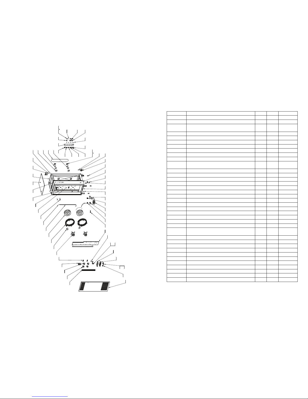
EXPLODED DIAGRAM - MAIN ASSEMBLY
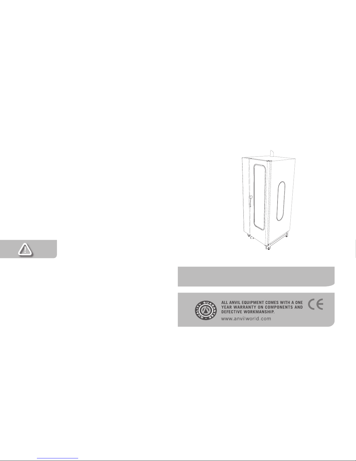
HEAVY DUTY ELECTRIC COMBI OVEN
MODEL CODE: COA1020
56
23
54
24 19
58
20
35
53
40
59
31
64
28
62
60
36
63
65
26
45
27
51
50
37
38
1514
41
1721
46
67
49
18
48
61
16
72
77
42 43
44
32
69
66 76
29
68
79
30
33
34
47
70 71
75
39
5755
78
74
73
25
52
22