AOpen AX4SPE Max II Datasheet

ATX Power Connector
AGP 8x Expansion Slot
supports 8X AGP card(2.1GB/s)
478-pin CPU socket (Northwood) with
Voltage and Frequency Auto-detection
that supports Intel®Pentium®4
1.6~3.06GHz+ CPU
Springdale-PE Chipsets that support 400/533/800
MHz FSB, DDR 400/333/266 and AGP 8X
Integrated 1394 controller
CPUFAN Connector
184-pin DIMMx4 supports 128bit dual
channel DDR400/333/266
Max. To 4GB
IDE Connector x2
(ATA33/66/100 supported)
IrDA Connector
Onboard AC’97 CODEC
AUX-IN Connector
32-bit PCI Expansion Slot x6
Game Port Connector
SYSFAN3 Connector
JP14 CMOS Data Clear Jumper
Low ESR Capacitors
S/PDIF Connecto
r
JP28 PS2 KB/Mouse Wakeu
p
Jum
p
e
r
CD-IN Connector
PS/2 Mouse
Connecto
r
SPP/EPP/ECP Parallel Port
USB 2.0
Ports RJ45 10/100
/
1000
LAN Jack
PS/2 Keyboard
Connecto
r
USB 2.0 Ports
COM 1 Port COM 2 Port
Line-In
MIC-In
Speaker
Out
AOpen reserves the right to revise all the specifications and information contained in this document, which are subject to change without notice.
Front Audio Connector
JP2 Speaker output Jumper
JP24 BIOS Rescue Jumper
USB 2.0 Connector
Front Panel Connector JP15/JP16 Dr. Voice II
Language Selection Jumper
Case Open Connector
Serial ATA Port x4
Supports 150 Mb/s Transfer Rate
FDD Connector
IEEE1394 Connector x 2
SYSFAN2 Connector
Die-hard BIOS
Resetable Fuse
Wake on LAN Connector
4-pin 12V ATX Power Connector
AGP Protection LED
STBY LED

1. JP14 Clear CMOS
2. JP28 Keyboard/Mouse Wakeup Jumpers
Everything you need to boot this
motherboard is included in this
Easy Installation Guide. For more
information, a complete Online
User's Manual can be found in the
Bonus Pack CD. Thanks for the
help of saving our earth.
PART NO: 49.8AT03.EE2 DOC. NO: AX4SPEMAX-EG-E0306B
Easy Installation Guide x 1
User Manual x 1
EzRestore Guide x 1
40-Wire IDE Cable x 1
80-Wire IDE Cable x 1
Floppy Drive Cable x 1
Serial ATA Cable x 2
IEEE1394 Cable x 1
USB2.0 Cable x 1
S/PDIF Cable x 1
SATA Power Cable x 1
Bonus Pack CD x 1
I/O Shield x 1
This motherboard provides keyboard / mouse wake-up function. You can use JP28 to enable or disable this
function, which could resume your system from suspend mode with keyboard or mouse. The factory default
setting is “Disable” (1-2), and you may enable this function by setting the jumper to 2-3.
You can clear CMOS to restore system default setting. To
clear the CMOS, follow the procedure below.
1. Turn off the system and unplug the AC power.
2. Remove ATX power cable from connector PWR2.
3. Locate JP14 and short pins 2-3 for a few seconds.
4. Return JP14 to its normal setting by shorting pin 1 & pin 2.
5. Connect ATX power cable back to connector PWR2.
Tip: When should I Clear CMOS?
1. Boot fails because of overclocking…
2. Forget password…
3. Troubleshooting…
Pin 1
Pin 1
Normal
(
default
)
1
Clear CMOS
1
Enable
Disable
(Default)
1 1

This motherboard comes with a 20-pin and 4-pin ATX power connector as shown below.
Make sure you plug in the right direction. We strongly recommend you to insert the 4-pin
connector before connecting the 20-pin connector.
1
5. Setting CPU Voltage & Frequency
4. Connecting Front Panel Cable
3. Connecting ATX Power Connector
Full-range Adjustable CPU Core Voltage
This motherboard supports CPU VID function. The CPU core voltage will be automatically
detected and the range is from 1.1V to 2.025V. It is not necessary to set CPU Core
Voltage.
Setting CPU Frequency
This motherboard is CPU jumper-less design, you can set CPU frequency through the
BIOS setup, and no jumpers or switches are needed.
BIOS Setup > Frequency / Voltage Control > CPU Bus Frequency
Core Frequency = CPU FSB Clock * CPU Ratio
CPU Ratio 8x, 10x… 21x, 22x, 23x, 24x
CPU FSB
(Adjustment manually) FSB = 100MHz-400MHz by 1MHz Stepping
CPU Overclocking
Northwood
CPU CPU Core
Frequency FSB
Clock System
Bus Ratio
Pentium 4 1.8G 1800MHz 100MHz 400MHz 18x
Pentium 4 2.0G 2000MHz 100MHz 400MHz 20x
Pentium 4 2.2G 2200MHz 100MHz 400MHz 22x
Pentium 4 2.2G 2200MHz 133MHz 533MHz 16x
Pentium 4 2.26G 2260MHz 133MHz 533MHz 17x
Pentium 4 2.4G 2400MHz 100MHz 400MHz 24x
Pentium 4 2.4G 2400MHz 133MHz 533MHz 18x
Pentium 4 2.53G 2530MHz 133MHz 533MHz 19x
Pentium 4 2.6G 2600MHz 200MHz 800MHz 13x
Pentium 4 2.66G 2660MHz 133MHz 533MHz 20x
Pentium 4 2.8G 2800MHz 133MHz 533MHz 21x
Pentium 4 2.8G 2800MHz 200MHz 800MHz 14x
Pentium 4 3.06G 3000MHz 200MHz 800MHz 15x
Attach the power LED, speaker, and reset switch connectors to the corresponding pins. If
you enable “Suspend Mode” item in BIOS Setup, the ACPI & Power LED will keep flashing
while the system is in suspend mode.
Locate the power switch cable from your ATX housing. It is 2-pin female connector from the
housing front panel. Plug this connector to the soft-power switch connector marked SPWR.
Speaker
IDE LED
SPWR
ACPI & PWR
LED
Reset
ACPI LED (BLUE)
15VSB
SPWR
ACPI LED-
GND
ACPILED
NC
ACPI_B
GND
RESET
GND
NC
NC
+5V
IDE LED
IDE LED
+5V
+5V
GND
NC
SPEAKER
Note: Intel Springdale-PE
chipset only support
Northwood processors,
and don’t support
Willamette or Celeron
processors. Northwood
processor would detect
the clock ratio
automatically, you may
not be able to adjust the
clock ratio in BIOS
manually.
Warning: Intel
Springdale-PE chipset
supports maximum
800MHz (200MHz*4)
system bus and
66MHz AGP clock;
higher clock setting
may cause serious
system damage.

7. Support USB 2.0 Connector
6. Dr. Voice II (Volume adjustable through speaker)
9. Support 10/100/1000 Mbps LAN onboard
The Dr. Voice II can identify what kind of problems had occurred in the operating system. It
provides four kinds language versions. You can select preferred language version by
JP15&JP16 jumpers. JP2 helps to select the voice coming out from buzzer or speaker. You
may set JP2 to pin 1-2 to enable buzzer or pin 2-3 to enable speaker.
This motherboard provides eight USB 2.0 ports to connect USB devices, such as
mouse, keyboard, modem, printer, etc. There are six ports on the back panel. You can
use proper cables to connect the Front USB connector to USB modules or front panel of
chassis.
8. IEEE 1394 Connector
With IEEE1394 MAC Embedded in Intel ICH5R (with AGERE FW323), the IEEE 1394
provides data transfer rate up to 400Mb/s, and USB 1.0/1.1just has 12Mbps. Hence, the
IEEE 1394 interface can connect with the devices that need high data transferring
performance, such as digital camera, scanner or others IEEE 1394 devices. Please use
the
p
ro
p
er cable to connect with devices.
Pin 1
Warning: Please be noted that
Hot-Plug in is not allowed on
IEEE 1394 header, because it will
burn the IC of the controller and
damage the motherboard.
On the strength of BCM5705, the fourth-generation triple-speed 10/100/100 base-T
Ethernet LAN Controller solution for high-performance network applications, this
motherboard provides 10/100/1000M bps Ethernet for office and home use. The Ethernet
RJ45 connector is located on top of USB connectors. The right hand side LED indicates
link mode, it lights in orange whenever linking to network. The left hand side LED
indicates the transfer mode and it lights in green when data is transferring in 100Mbps
(never lights while in 10Mbps), but lights in orange when transferring in Gigabit’s mode. To
enable or disable this function, you may simply adjust it through BIOS.
Dr. Voice Language
Select Jum
p
e
r
JP15 JP16
Pin1
Pin1
Pi
n
1
Buzzer
(
default
)
1
Speaker
1
JP2 Speaker Output
+5V
SBD7-
SBD7+
GND
NC
+5V
SBD6-
SBD6+
GND
KEY
USB 2.0 Connector
1
SHIED GND
+12V(Fused)
TPB-
GND
TPA-
+12V(Fused)
TPB+
GND
TPA+
10 9
2 1
Pi
n
1
Pi
n
1
Transferring (Left)
Green 100Mbps
Orange Gigabit Linking (Right)
Orange

11. Connecting Serial ATA Connector
10. Connecting IrDA Connector 12. S/PDIF (Sony/Philips Digital Interface) Connector
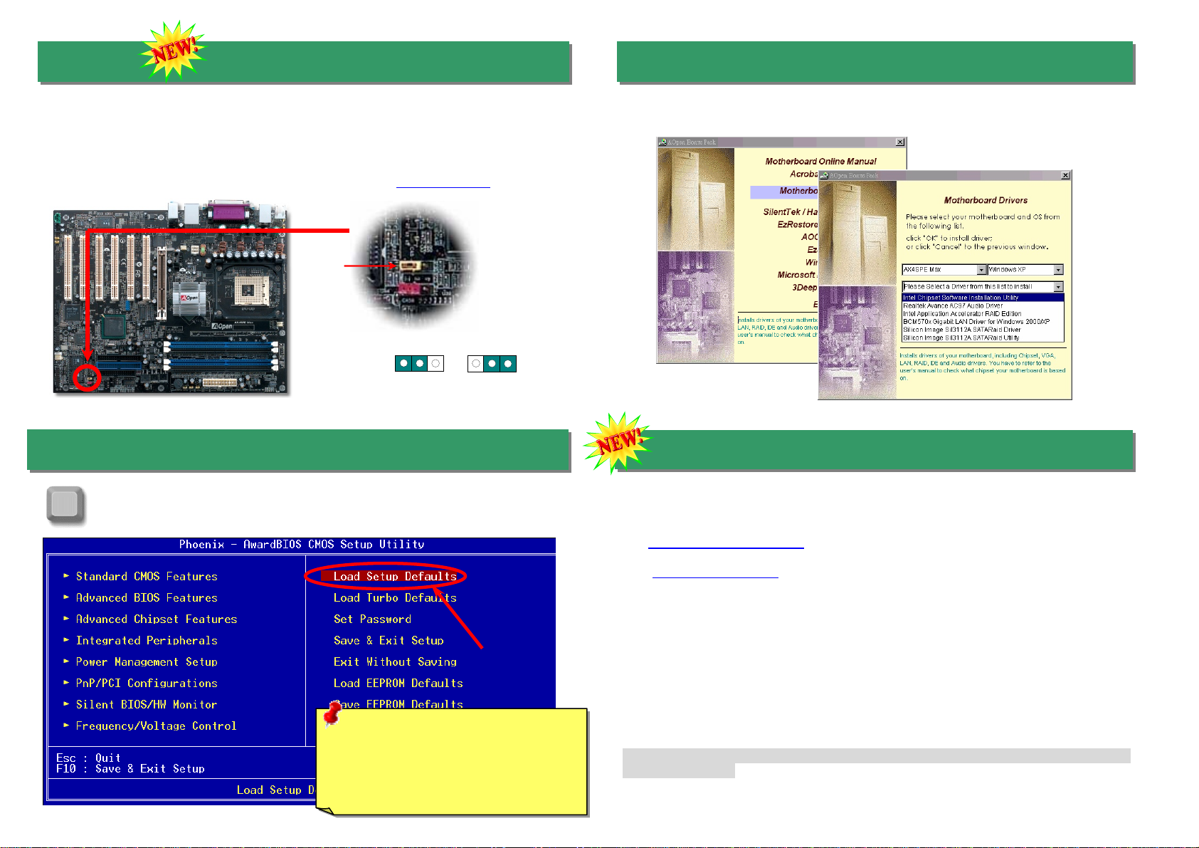
The IrDA connector can be configured to support wireless infrared module, with this
module and application software such as Laplink or Windows 98 Direct Cable Connection,
the user can transfer files to or from laptops, notebooks, PDA devices and printers. This
connector supports HPSIR (115.2Kbps, 2 meters) andASK-IR (56Kbps).
Install the infrared module onto the IrDA connector and enable the infrared function from
BIOS Setup, UART mode select, make sure to have the correct orientation when you plug
in the IrDA connector.
Pin 1
S/PDIF (Sony/Philips Digital Interface) is a newest audio transfer file format, which provides
impressive audio quality through optical fiber and allows you to enjoy digital audio instead of
analog audio. Through a specific audio cable, you can connect the S/PDIF connector to other
end of the S/PDIF audio module, which bears S/PDIF digital output. Normally there are two
S/PDIF outputs as shown, one for RCA connector, the most common one used for consumer
audio products, and the other for optical connector with better audio quality. Same as outputs,
you can also connect RCA or optical audio products to input connectors on the module and
have the voice or music come out from your computer. However, you must have a S/PDIF
supported speaker/amplifier/decoder with S/PDIF digital input/output to connect to the S/PDIF
digital input/output to make the most out of this function.
Pin 1
S/PDIF Module
(User Upgrade Optional)
S/PDIF
Cable
S/PDIF OUT
S/PDIF IN
(RCA)
S/PDIF IN
(
O
p
tical
)
S/PDIF OUT
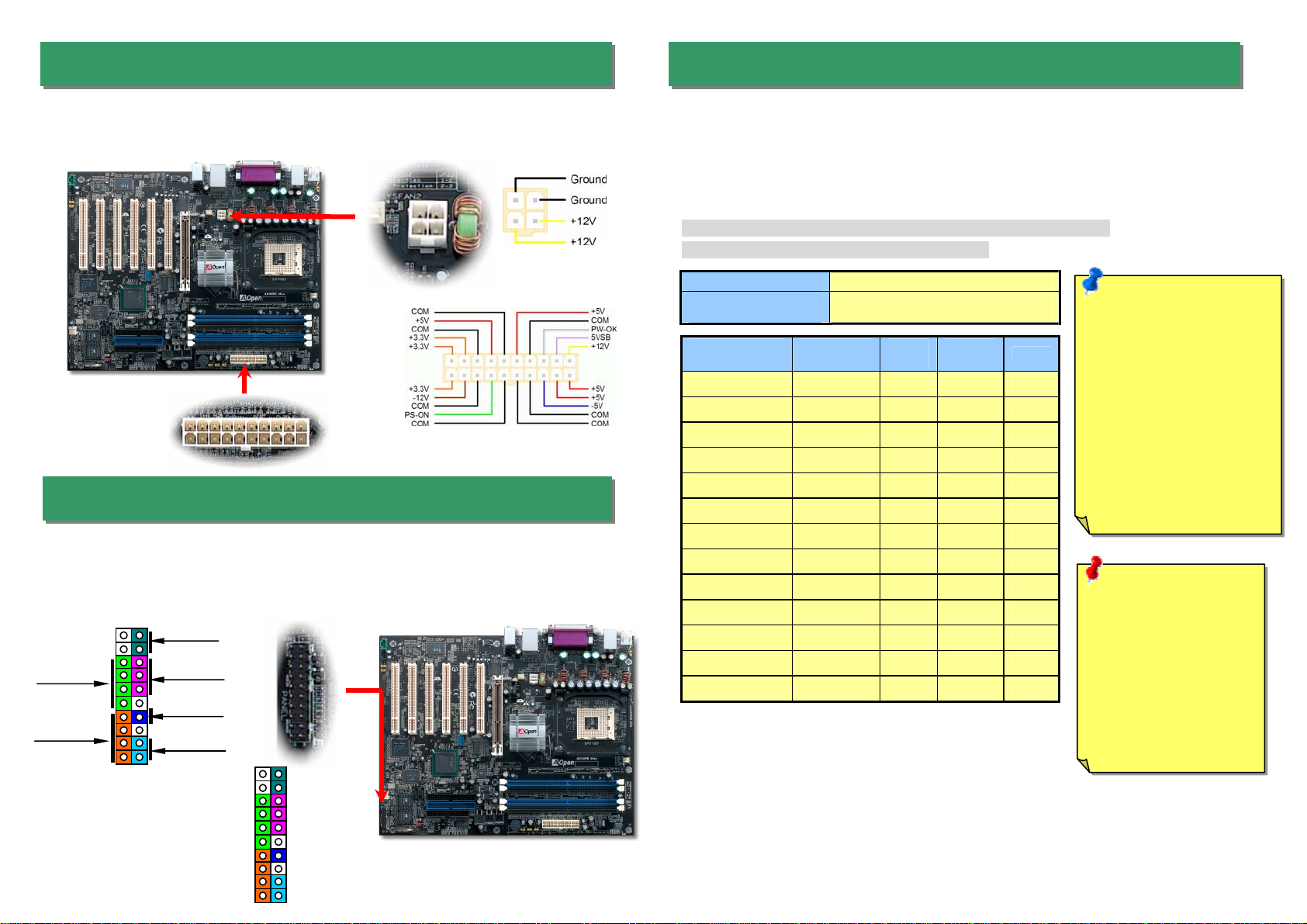
13. Super 5.1 Channel Audio Effects
This motherboard comes with an ALC650 CODEC, which supports high quality of 5.1
Channel audio effects, bringing you a brand new audio experience. On the strength of the
innovative design of ALC650, you're able to use standard line-jacks for surround audio output
without connecting any external module. To apply this function, you have to install the audio
driver in the Bonus Pack CD as well as an audio application supporting 5.1 Channel. Picture
bellow represents the standard location of all speakers in 5.1Channel sound track. Please
connect the plug of your front speakers to the green “Speaker out” port, rear speakers’ plug
to the blue “Line in” port and both of the center and subwoofer speakers to the red “MIC in”
port.
IrDA Connector
1 KEY
GND
IR_RX
NC
+5V
IR_TX
To connect a Serial ATA disk, you must use a 7-pin serial ATA cable. Connect two ends of
the serial ATA cable to the serial ATA header on the main board and the disk. Like every
other traditional disk, you also have to connect a power cable. Please note that it is a
jumper free implement; you don’t need to set jumpers to define a master or slave disk.
When connecting two serial ATA disks, the system will automatically take the one
connected to “Serial ATA 1” header as a master disk.
5
1+5V
NC
SPDIFOUT
GND
SPDIFIN
SATA port 4 (Sil 3112)
SATA port 3 (Sil 3112)
SATA port 1 (ICH5R) SATA port 2 (ICH5R)

After you finish the setting of jumpers and connect correct cables. Power on
and enter the BIOS Setup, press <Del> during POST (Power On Self Test).
Choose "Load Setup Defaults" for recommended optimal performance.
15. Power-on and Load BIOS Setup
16. AOpen Bonus Pack CD
You can use the autorun menu of Bonus CD. Choose the utility and driver and select
model name.
Del
Warning: Please avoid of using "Load
Turbo Defaults", unless you are sure
your system components (CPU, RAM,
HDD, etc.) are good enough for turbo
setting.
14. Die Hard BIOS
17. BIOS Upgrade under Windows Environment
You may accomplish BIOS upgrade procedure with EzWinFlash by the following steps,
and it’s STRONGLY RECOMMENDED to close all the applications before you start the
upgrading.
1. Download the new version of BIOS package zip file from AOpen official web site. (ex:
http://english.aopen.com.tw)
2. Unzip the download BIOS package (ex: WSPEMAX102.ZIP) with WinZip
(http://www.winzip.com) in Windows environment.
3. Save the unzipped files into a folder, for example, WSPEMAX102.EXE &
WSPEMAX102.BIN.
4. Double click on the WSPEMAX102.EXE, EzWinFlash will detect the model name
and BIOS version of your motherboard. If you had got the wrong BIOS, you will not
be allowed to proceed with the flash steps.
5. You may select preferred language in the main menu, then click [Start Flash] to start
the BIOS upgrade procedure.
6. EzWinFlash will complete all the process automatically, and a dialogue box will pop
up to ask you to restart Windows. You may click [YES] to reboot Windows.
7. Press <Del> at POST to enter BIOS setup, choose "Load Setup Defaults", then
“Save & Exit Setup”. Done!
It is strongly recommended NOT to turn off the power or run any application during
FLASH PROCESS.
Many viruses have been found that they may destroy bios code and data area lately. This
motherboard implements a very effective hardware protection method without any software or
BIOS coding involved, therefore it is 100% virus free. You may restore the originally mounted
BIOS with 2nd BIOS ROM by setting JP24 to pin 2-3 if it fails to work properly. This
motherboard comes with one BIOS ROM; you may contact our local distributors or resellers
for purchasing an extra BIOS ROM. Please visit our website at www.aopen.com for details.
Normal Rescue ROM
11
JP24
Pin1

If you encounter any trouble to boot you system, follow the procedures
accordingly to resolve the problem.
Part Number and Serial Number
The Part Number and Serial number are printed on bar code label. You can find this
bar code label on the outside packing, on component side of PCB. For example:
Model name and BIOS version
AX4SPE Max R1.00 Mar. 01. 2003 AOpen Inc.
Award Plug and Play BIOS Extension v1.0A
Copyright © 2003, Award Software, Inc.
Model name and BIOS version can be found on upper left corner of first boot screen
(POST screen). For example:
AX4SPE Max is model name of motherboard; R1.00 is BIOS version
P/N: 91.88110.201 is part number, S/N: 91949378KN73 is serial number.
Part No. Serial No.
Part No. Serial No.
Make sure if the jumper settings for CPU and DRAMs are correct.
Clear CMOS, then plug the ATX power cord correctly.
(For P4 system, please also plug the 4pin(+12V) cord.
Install the VGAcard. Then connect your monitor and keyboard.
The problem was probably caused
by power supply or motherboard
failure. Please contact your reseller
or local distributor for repairing.
Perhaps your VGA card or monitor
is defective.
No
Yes
No
Yes
It is very possible that your keyboard
is defective.
During system rebooting, press Del to enter BIOS Setup. Choose
“Load Setup Default".
The problem should be caused by the
IDE cables or HDD itself.
Re-install Windows 95, Windows 98 or Windows NT.
Yes
Yes
Turn off the power and unplug the AC power cable, then remove all
of the addon cards and cables, including VGA, IDE, FDD, COM1,
COM2 and Printer.
Turn on the power, and check if
the power supply and CPU fan
work properly.
Start
Check if there is display.
Press Ctrl, and Alt key at the
same time, hold them and then
press Del to see if the
s
y
stem reboots.
Turn off the system and
re-connect the IDE cable.
Check if the system can
reboot successfully.
End
No
No

Dear Customer,
Thanks for choosing AOpen products. To provide the best and fastest service to
our customer is our first priority. However, we receive numerous emails and
phone-calls worldwide everyday; it is very hard for us to serve everyone on time.
We recommend you to follow the procedures below and seek help before
contacting us. With your help, we can then continue to provide the best quality
service to more customers.
Thanks very much for your understanding!
AOpen Technical Supporting Team
Web Site: http://www.aopen.com.tw
E-mail: Send us email by going through the contact form below.
English http://english.aopen.com.tw/tech/default.htm
Japanese http://www.aopen.co.jp/tech/default.htm
Chinese http://www.aopen.com.tw/tech/default.htm
German http://www.aopencom.de/tech/default.htm
Simplified Chinese http://www.aopen.com.cn/tech/default.htm
Pacific Rim
AOpen Inc.
Tel: 886-2-3789-5888
Fax: 886-2-3789-5899
Europe
AOpen Computer b.v.
Tel: 31-73-645-9516
Email:[email protected]
Germany
AOpen Computer GmbH.
Tel: 49-1805-559191
Fax: 49-2102-157799
China
艾爾鵬國際貿易(上海)有限公司
Tel: 86-21-6225-8622
Fax: 86-21-6225-7926
Japan
AOpen Japan Inc.
Tel: 81-048-290-1800
Fax: 81-048-290-1820
America
AOpen America Inc.
Tel: 1-510-489-8928
Fax: 1-510-489-1998
Online Manual: To download manual, please log on and then select your
preferred language. Under “Type” directory, choose “Manuals” to go to our
manual database. You can also find the manual and EIG in AOpen Bonus Pack.
http://download.aopen.com.tw/downloads
1
1
Test Report: We recommend you to choose board/card/device from the
compatibility test reports for assembling your PC. It may prevent incompatibility
problems.
http://english.aopen.com.tw/tech/report/default.htm
2
2
FAQ: Here we list problems that users often encounter and FAQ
(Frequently Asked Questions). You may select your preferred language
after log on, and may be able to find a solution to your problem.
http://club.aopen.com.tw/faq/
5
5
Download Software: After log on and having language selected, you may
get the latest updated BIOS/utility and drivers you need under “Type”
directory. In most case, newer versions of drivers and BIOS have solved
earlier bugs or compatibility problems.
http://download.aopen.com.tw/downloads
3
3
eForum: AOpen eForum is provided to discuss our products with other users, in
which your problem probably had been discussed before or will be answered.
After log on, you may select your preferred language under “Multi-language”.
http://club.aopen.com.tw/forum/
4
4
Contact Distributors/Resellers: We sell our products through resellers
and integrators. They should know your system configuration very well
and should be able to solve your problem efficiently and provide important
reference for you.
6
6
Contact Us: Please prepare detail system configuration and error
symptom before contacting us. The part number, serial number
and BIOS version are also very helpful.
7
7
Other manuals for AX4SPE Max II
2
Table of contents
Other AOpen Motherboard manuals

AOpen
AOpen XC CUBE UX915G User manual

AOpen
AOpen NMCP68ST User manual

AOpen
AOpen s661FXm-7S Datasheet

AOpen
AOpen MX3ZA User manual

AOpen
AOpen AX6BC PROII Datasheet

AOpen
AOpen AX37 PRO Setup guide

AOpen
AOpen AX45H-8X Max Setup guide

AOpen
AOpen MX6B EZ Installation guide

AOpen
AOpen AP5VM User manual

AOpen
AOpen DXPL-U User manual

AOpen
AOpen AX4T II-133 Setup guide

AOpen
AOpen AK33 M Datasheet

AOpen
AOpen AX34 Pro II Datasheet

AOpen
AOpen AK79G TUBE Setup guide

AOpen
AOpen AK77-8X Datasheet

AOpen
AOpen MX4GVR Setup guide

AOpen
AOpen VKM400AM-S User manual

AOpen
AOpen MX46U2-VN Setup guide

AOpen
AOpen MX46-800N Datasheet

AOpen
AOpen AX3S-1394 Datasheet