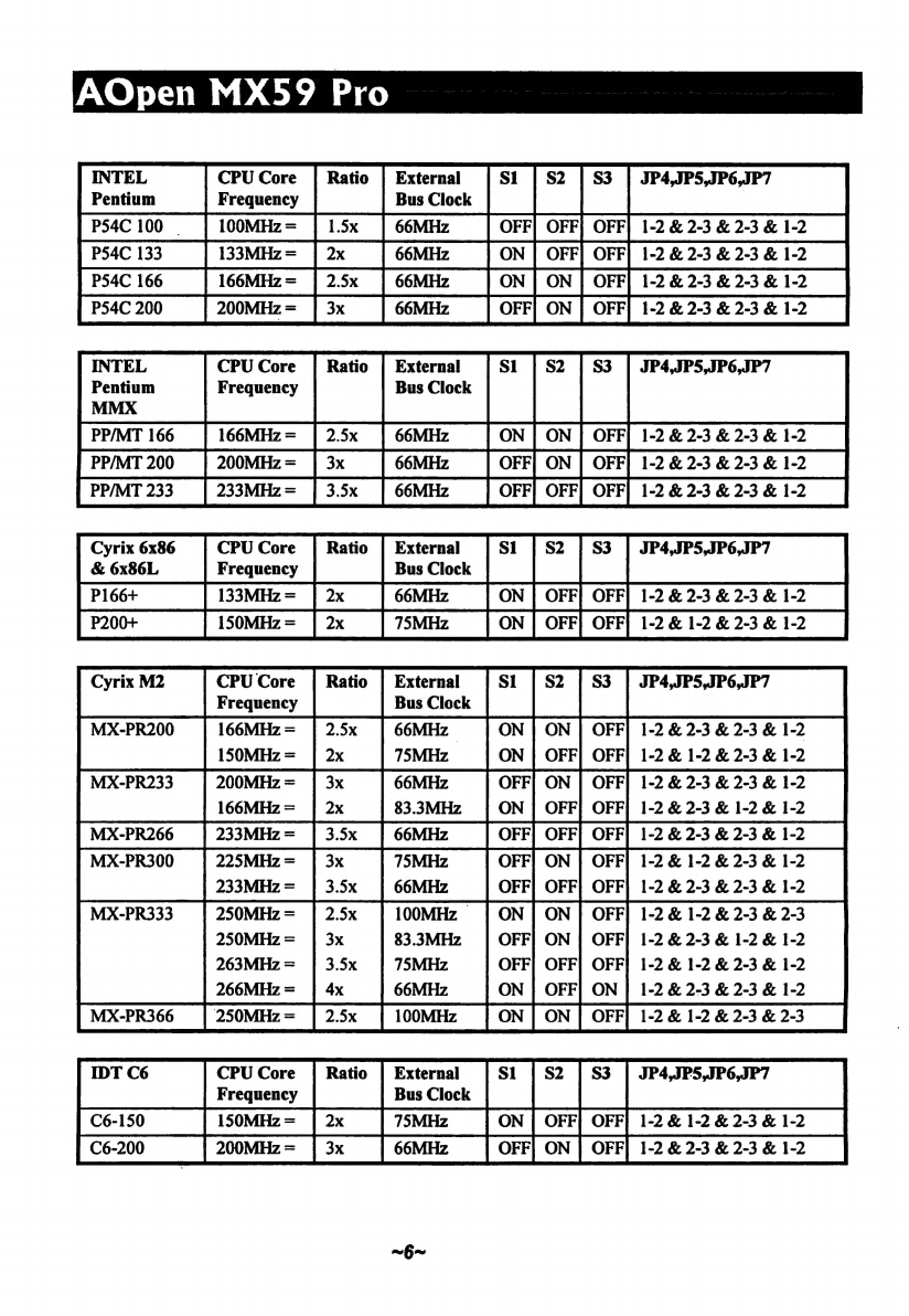
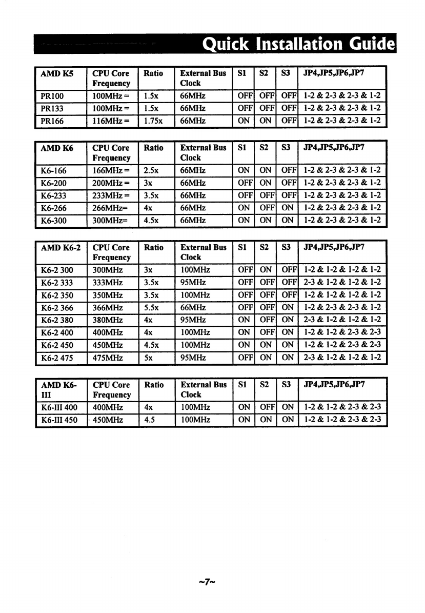
AOpen MX59 Pro User manual

teat
~
мо
OTHERBOARD
MX59
Pro
Quick
Installation
Guide
VOpen
Manual
CD
Included
Component
Solutions

Quick
Installation
Guide
Overview
Specification:
CPU
Intel
Pentium
Processor
P54C,
PP/MT
(P55C),
AMD
K5/K6/K6-2/K6e-Ill,
Cyrix
6x86/M2
and
IDT
WinChip
C6
family.
Chipset
VIA
MVP4
AGPset.
Architecture
Cache
Onboard
ИО
Board
Size
|
220mmx245mm
——
—
|
Key
Features:
Full-range
CPU
core
voltage
(from
1.3V
to
3.5V,
0.05V
or
0.1V
per
step)
Support
100MHz
external
clock
and
Clock
Generator
Up
to
124
MHz
for
Overclockers
Onchip
Audio
and
AGP
Zero
Voltage
Wake
On
Modem
Wake
On
LAN
Wake
On
RTC
Timer
High
Efficient
Synchronous
Switching
Regulator
Over
Current
Protection
Circuit
Keyboard
&
USB
Resetable
Fuse
Protection
CPU
and
Housing
Fan
Monitoring
CPU
Thermal
Protection
System
Voltage
Monitoring
Support
DMI
Function
FCC
DoC
&
CE
Certification
AOpen
Bonus
Pack
CD
disc
(Norton
Antivirus
Included)
Note:
This
Quick
Installation
Guide
is
only
for
quick
reference.
For
more
information,
=>
please
see
also
to
Те
online
User's
manual
in
те
AOpen
Bonus
Pack
CD
disc.
Item
Checklist
Please
check
if
your
package
is
complete
according
to
the
following
checklist.
Motherboard
x1
IDE
cables
x1
Floppy
drive
cable
x1
AOpen
Bonus
Pack
CD
disc
x1
Quick
Installation
Guide
x1
DOOODODOODODOODOOO
НЕЕ

AOpen
MX59
Pro
|
/
Jumper
and
Connector
Locations:
MODEM
CN
WOL
сом
с
В
c
I I
3
2
p^
PRINTER
PS/2
Mouse
USB
PS/2
Keyboard
COMI
VGA
Game
Port
SW1:
DIP
Switch
for
CPU
voltage
and
clock
ratio
JP4,
JP5,
JP6,JP7
СРО
external
clock
JP
12:
CPU
I/O
Voltage
JP14:
Clear
CMOS
Connectors:
PWR2:
ATX
power
connector
USB:
USB
connector
~2~

FDC:
IDE1:
IDE2:
CPUFAN!1:
CDUFAN?2:
FAN:
IrDA:
PANEL:
:
CD-IN:
MODEM-CN:
WOM:
WOL:
Floppy
drive
connector
IDE1
primary
channel
IDE2
secondary
channel
CPU
fan
connector
CPU
fan
connector
Fan
connector
IrDA
(Infrared)
connector
Front
panel
(Multifunction)
connector
CD-audio
connector
Mono
in
(Pin
1-2)
and
Mic
out
(Pin
3-4)
OV
Wake
On
Modem
connector
Wake
On
LAN
connector
~3~
Quick
Installation
Guide

AOpen
MX59
Pro
|
mm
Hardware
Installation
Please
follow
the
steps
below
to
configure
your
motherboard.
1.
Plugging
CPU
and
Connecting
CPU
Fan
Plug
in
the
fan
cable
to
the
fan
connectors
onboard.
The
fan
connectors
are
marked
CPUFAN1,
CPUFAN2
and
FAN
on
the
system
board.
You
can
plug
the
CPU
fan
cable
to
both
the
2-рт
fan
connector
CPUFAN1
and
(ће
3-
pin
fan
connector
CPUFAN2.
FAN
can
be
reserved
for
the
housing
fan.
Note
that
only
CPUFAN2
and
FAN
support
the fan
monitoring
function,
because
3-pin
fan
has
an
extra
pin
called
SENSE,
which
periodically
sends
fan
signal
out.
2.
Setting
CPU
Core
Voltage
Please
refer
to
manual
in
AOpen
Bonus
Pack
CD.
There
are
32
settings,
from
1.3V
to
2.1V
(0.05V
per
step.)
and
from
2.1V
to
3.5V
(0.1V
per
step).
ON
ON
E
dn
не
Ш]
3.52V
2.9V
rj
CJ
6x86
or
K5
K6-166/200
or
M2
===
ON
ON
3.45V
2.8V
P54C
P55C
(MMX)
ON
ON
3.3V
2.4V
IDT
C6
K6-2
400/450/475
and
Кб-И!
ON
ON
32V
22V
K6-233
K6-266/300
and
K6-2
~4~

Quick
Installation
Guide
3.
Selecting
the
CPU
Frequency
CPU
Frequency
=
Ratio
*
External
Bus
Clock
“i
T
Y
.
ON ON
1.5х
(3.5x)
4x
ON
|
ON
2x
(6x,
3.33x)
4.5x
ON
ON
2.5x
(1.75x)
5х
(2.33x)
ON
ON
3x
5.5x
(2.66x)
JP4
5
JP6
JP7
о]
[о]
[0]
М
m
m
mu
EN
N
No
CPU:
60MHz
PCI:
30MHz
ЈРА
JPS
JP6
JP7
B
o o
|
и
g
ш
oj
MI MI
[0]
CPU:
66.8MHz
PCI:
33.4MHz
JP4 JPS
JPG
JP7
fo}
m
[o
№
g
Ema
Eo
No
CPU:
70MHz
PCI:
35MHz
JP4
JPS
JP6
JP7
E
E
ic]
g
"n
О]
[0]
MI
[0]
CPU:
75MHz
PCI:
25MHz
JP4
ЈР5
JP6
ЈР7
jo
[ol
[9]
[0]
ENEN
E
= = и
CPU:
75MHz
PCI:
37.5MHz
JP4
JPS
JP6
JP7
о]
[0]
N
NE
EH
= и
M
NIC
CPU:
80MHz
PCI:
28.5MHz
JP4
JPS
JP6
JP7
|
[9]
[9]
9]
"n
oj
MIN
M
CPU:
80MHz
PCI:
40MHz
JP4
JPS
JP6
JP7
mom
E
mH
о]
MI
[9]
[0]
CPU:
83.3MHz
PCI:
27.7MHz
JP4
JPS
JP6
JP7
oj
M о о
[
ML
Ш
Ш
Eo
NM
CPU:
83.3MHz
PCI:
41.7MHz
JP4
JPS
JP6
JP7
о
И
ma
"Idas
L
lo]
[0]
[0
CPU:
95.3MHz
PCI:
31.6MHz
~Б~
ЈРА JPS
JP6
JP7
gu
mM
NIMM
о]
[0] [0]
[0]
CPU:
100MHz
PCI:
33.3MHz
JP4
JPS
JP6
JP7
JP4
ЈР5
JP6
JP7
E
EH
H^
M
NNI
Ii
o:
[0]
[0]
NI
CPU:
124MHz
PCI:
41.3MHz

AOpen
MX59
Pro
INTEL
CPU
Core
|
Ratio
|
External
JP4,JP5,JP6,JP7
im
[meme
|
|
види
|
|-
|p
[540100
—
|
100MHz=
[sk
|
eomme
|
OFF|
OFF| OFF|
12&
23
&
23
&
12
[Ps4C133
__|
133MHiz=
|2x
|
ввмнг
_|
ом
|
OFF
OFF|
12823823812
[540166
|
166MHz=
[25x
[вм
__|
ON]
ом
|
OFF|
12823823812
|
Раса
|
200MHz=
|
зх
[вмиг
|
OFF|
ON
|
OFF]
12823823812
INTEL
CPU
Core
|
Ratio
|
External
JP4,JP5,JP6,JP7
Pentium
Frequency
Bus
Clock
MMX
PPMT166
|
166MHz=
[25x
|
66MHz
|
ом ON
|
OFF|
12823823812
|
PPIMT
200
|
200MHz=
|
зх
|
66MHz
|
оте]
ON
|
OFF]
12823823812
|
[pri
233
|
233MHa=
|
ээх
|
oom
_|
OFF]
OFF| orr|
1223
&23
&
12
Cyrix
6x86
CPU
Core
|
Ratio
|
External
JP4,JP5,JP6,JP7
&
6x86L
Frequency
Bus
Clock
ples
—
[133MHz-
[2x
|
66MHz
|
ом
|
OFF| OFF|
12&23
&
23
&
12
P200
|
пзомна
=
12&12&23&12
E
ER
RR
dic
Bus
Clock
MX-PR200
166MHz
=
66MHz
ON
ua
OFF]
1-2
&
2-3
&
2-3
&
1-2
MX-PR233
200MHz=
|
3x
66MHz
OFF]
ON
|
OFF]
1-2
&
2-3
&
2-3
&
1-2
НЕ
=
el
[MXPROG
|
|
66MHz
|
OFF|
OFF|
Orr|12823&23&12
—
pu
225MHz
=
3x
=
ms
ОМ
|
OFF|
1-2
&
1-2
&
2-3
&
1-2
233MHz=
|
3.5x
66MHz
OFF]
OFF}
OFF}
1-2
&
2-3
&
2-3
&
1-2
MX-PR333
2.5x
ON
|
ON
|
OFF]
1-2
&
1-2
&
2-3
&
2-3
3x
OFF|
ON
|
OFF|
1-2
&
2-3
&
1-2
&
1-2
3.5х
OFF|
OFF]
OFF]
1-2
&
1-2
&
2-3
&
1-2
4x
ОМ
|
OFF]
ON
|
1-2
&
2-3
&
2-3
&
1-2
acras
|
зомне=
|
25
_[оомн
[ON
ON
|
оваа
12825823
IDT
C6
CPU
Core
|
Ratio
|
External
JP4,JP5,JP6,JP7
Frequency
Bus
Clock
[Cei
___|
пзомна=
[2x
[75мнё
[ом
[ЕР
OFF|
12&12&23&
12
L
MMC
AER
АК
ET
IET

Quick
Installation
Guide
AMD
K5
CPU
Core
|
Ratio
External
Bus
JP4,JP5,JP6,JP7
Frequency
Clock
ко
_|
помно
=
|
15x
|
емна
|
OFF| OFF|
OFF|
12823823
&
12
PR133
100MHz
=
OFF|
OFF|
OFF|
1-2&2-3&2-3&
1-2
IRI
__|
поомна
=
[15x
|
вемне
—
|
OFF|
OFF|
OFF
PRI66
|
пемве=
[175
|вемне
—
[ом
|
ом
[ог
12423823812
"n
Frequency
Clock
OFF|
ON
|
OFF|
1-2
&2-3
&23
&
12
233MHz
=
[Ké266
|269MHz-
|а
—
|66MHz
__|
ON]
OFF|
ОМ
|
12&23&23&12-
300MHz-
|
45x
—
1-2
&
2-3
&
2-3
&
1-2
AMD
K6-2
|
СРО
Соге
|
Ratio
External
Bus
JP4,JP5,JP6,JP7
Frequency
Clock
OFF|
OFF}
OFF|
2-3
&
1-2
&
1-2
&
1-2
128612812812
OFF|
orr|
ON
|
1-2
&
2-3
&
23
&
12
[K62380
_|
звомна
[4x
__|
ззмна
‘|
ON|
OFF|
ON
|
23412812812
[Ke240
|40MHz
|4x
|10MHz
[ом
|
OFF|
ON
|
12812823823,
[Ké2450
_|
азомна
[45x
|10MHz
|
ON|
ON]
ON|
12812823823
Kezar
|45MH;
|se
__|
ми,
|
OFF
ох
[оч
|
23212612812
AMD
K6-
|
CPUCore
|
Ratio
|
External
Bus
JP4,JP5,JP6,JP7
HI
Frequency
Clock
K6-III
400
|
400MHz
|4х
|
100MHz
1-2
&
1-2
&
2-3
&
2-3
K6-III450
|
450MHz
|
45
100MHz
1-2
&
1-2
&
2-3
&
23

АОреп
MX59
Pro
4.
Connecting
Front
Panel
Cable
and
Power
Cable
Attach
the
power
LED,
keylock,
speaker,
and
reset
switch
connectors
to
the
corresponding
pins.
If
you
enable
"Suspend
Mode"
item
in
BIOS
Setup,
the
ACPI
&
Power
LED
will
keep
flashing
while
the
system
is
in
suspend
mode.
Locate
the
power
switch
cable
from
your
ATX
housing.
It
is
2-pin
female
connector
from
the
housing
front
panel.
Plug
this
connector
to
the
soft-power
switch
connector
marked
SPWR.
5.
Plug
memory
module
and
FDC
and
IDE
cables.
Be
careful
of
the
pin1
orientation.
Wrong
orientation
may
cause
system
damage.
Please
refer
to
the
diagram
on
page
2.
6.
Power
On
and
Load
BIOS
Setup
Default
To
enter
the
BIOS
Setup,
press
during
POST
(Power-On
Self
Test).
Choose
"Load
Setup
Defaults"
for
recommended
optimal
performance.
Please
avoid
of
using
"Load
Turbo
Defaults",
unless
you're
sure
your
system
components
(CPU,
DRAM,
HDD,
etc.)
are
good
enough
for
turbo
setting.
For
detailed
information,
please
refer
to
"
AWARD
BIOS"
section
in
the
User's
Manual.
7.
Onchip
Audio
and
AGP
This
motherboard
comes
with
an
onchip
16-bit
sound
processor
and
a
high
performance
onboard
graphics
accelerator.

Quick
Installation
Guide
Software
Installation
For
installing
Windows
95,
please
make
sure
you
have
followed
below
procedures.
1.
First,
don't
install
any
add-on
card.
2.
Install
Window
95
into
your
system.
3.
Install
Windows
95
OSR2
v2.1,
1212
or
1214
version
and
later
with
USB
support.
Otherwise,
you
need
to
install
USBSUPP.EXE.
4.
Install
the
VIA
4
in
1
driver,
which
includes
VIA
Bus
Master
IDE
Driver,
AGP
Vxd
driver,
IRQ
routing
driver,
and
VIA
chipset
function
registry
program.
5.
Install
the
onchip
AGP
driver.
6.
Install
the
onchip
audio
driver.
7.
Finally,
Install
other
add-on
cards.
For
installing
Windows
98,
please
make
sure
you
have
followed
below
procedures.
1.
First,
don't
install
any
add-on
card.
2.
Enable
USB
Controller
in
BIOS
Setup
menu
to
make
BIOS
fully
capable
of
controlling
IRQ
assignment.
3.
Install
Window
98
into
your
system.
4.
Install
the
VIA
4
in
1
driver,
which
includes
VIA
Bus
Master
IDE
Driver,
AGP
Vxd
driver,
IRQ
routing
driver,
and
VIA
chipset
function
registry
program.
5.
Install
the
onchip
AGP
driver.
6.
Install
the
onchip
audio
driver.
7.
Finally,
Install
other
add-on
cards.
In
the
AOpen
Bonus
Pack
CD
disc,
you
can
find
above
drivers
in
the
path
X:\Mx59pro\Driver
(Where
X:
represents
your
CDROM
drive).
CN
Note:
Make
sure
you
have
set
the
display
mode
to
the
default
setting
(640
x
EV
480,
16
colors)
prior
to
uninstalling
the
VIA
4
in
1
driver.
Note:
Both
VIA
AGP
driver
and
audio
driver
don't
support
Windows
NT.
~д~

АОреп
MX59
Pro
Frequently
Asked
Questions
The
following
sections
are
not
a
must
to
install
this
motherboard,
they
are
list
here
for
your
reference.
How
to
Upgrade
BIOS?
AOpen
Easy
Flash
is
more
user
friendly
than
traditional
flash
method.
The
BIOS
binary
file
and
flash
routine
are
combined
together
and
you
simply
run
a
single
file
to
complete
the
flash
process.
1;
2.
3.
4.
5.
Get
new
BIOS
upgrade
program
from
AOpen's
web
site.
For
example,
MX59P200.EXE.
Reboot
the
system
to
DOS
mode
without
loading
any
memory
handler
(such
as
EMM386)
or
device
driver.
It
needs
around
520K
free
memory
space.
Execute
А:>
MX59P200
DO
NOT
turn
off
the
power
during
FLASH
PROCESS.
Reboot
the
system
by
turn
off
the
power
after
flash
is
completed.
Reload
the
"BIOS
SETUP
DEFAULT"
and
reconfigure
other
items
as
previous
set.
Save
&
Exit.
Done!
Note:
The
upgrade
of
new
BIOS
will
permanently
replace
your
original
BIOS
content
after
flashing.
The
original
BIOS
setting
and
Win95/Win98
PnP
information
will
be
refreshed
and
you
probably
need
to
re-configure
your
system.
How
to
Clear
CMOS?
Clear
CMOS
You
need
to
clear
the
CMOS
if
you
forget
your
system
password.
Normal
operation
|
To
clear
the
CMOS,
follow
below
procedures:
(default)
Clear
CMOS
oOarhon
>
JP14
JP14
1 1
[5
2
||
2
№
3
[о
з
Ш
Normal
Operation
Clear
CMOS
(default)
Turn
off
the
system
and
unplug
the
AC
power.
Remove
ATX
power
cable
from
connector
PWR2.
Locate
JP14
and
short
pins
2-3
for
a
few
seconds.
Return
JP14
to
its
normal
setting
by
shorting
pins
1-2.
Connect
ATX
power
cable
back
to
connector
PWR2.
Turn
on
the
system
power.
What
is
Hardware
Monitoring?
You
can
install
Hardware
Monitoring
Utility
to
monitor
CPU
temperature,
fans
and
system
voltage,
etc.
For
more
information,
please
see
the
online
manual
in
AOpen
Bonus
Pack
CD
disc.
Ultra
DMA/66
IDE
Hard
Drive
This
motherboard
supports
Ultra
DMA/66.
To
install
UDMA/66
HDD,
a
80-pin
IDE
cable
is
required.
~10~

|
Quick
Installation
Guide
Troubleshooting
If
you
encounter
any
trouble
to
boot
you
system,
follow
the
procedures
accordingly
to
resolve
the
problem.
Тит
off
the
power
and
unplug
the
AC
power
cable,
then
remove
all
of
the
addon
cards
and
cables,
including
VGA,
IDE,
FDD,
COM1,
COM2
and
Printer.
Make
sure
if
the
jumper
settings
for
CPU
and
DRAMs
are
correct.
Clear
CMOS.
Install
the
VGA
card.
Then
connect
your
monitor
and
keyboard.
The
problem
was
probably
caused
by
power
supply
or
motherboard
failure.
Please
contact
your
reseller
or
(оса!
distributor
for
repairing.
um
on
the
power,
and
check
if
the
power
supply
and
СР
No
fan
work
property.
Yes
Check
if
there
Is
display.
No
Анни
your
VGA
card
or
monitor
is
Yes
Press
СШ,
and
АН
key
at
the
same
time,
hold
them
and
then
press
Del
to
see
if
the
system
reboots.
Yes
During
system
rebooting,
press
Del
to
enter
BIOS
Setup.
Choose
"Load
Setup
Default”.
Tum
off
the
system
and
re-connect
the
IDE
cable.Chec
if
the
system
can
reboot
successfully.
No
The
problem
should
be
caused
by
the
IDE
cables
or
HDD
itself.
No
it
is
very
possible
that
your
keyboard
is
defective.
Yes
Re-install
Windows
95,
Windows
98
or
Windows
NT

AOpen
MX59
Pro
|
|
Technical
Support
Dear
Customers:
Thanks
of
choosing
AOpen
products.
Provide
best
and
fast
service
to
our
customer
is
our
first
priority,
but
we
receive
numerous
emails
and
phone
calls
worldwide
everyday,
it
is
very
hard
for
us
to
serve
everyone
on
time.
We
recommend
you
follow
below
procedures
to
seek
help
before
contact
us.
With
your
help,
we
can
then
continue
to
provide
the
best
quality
service
to
more
customers.
Thanks
very
much
of
your
understanding!
AOpen
Technical
Supporting
Team
Q
Online
Manual:
The
complete
manual
is
in
the
companion
CD
disc
—
AOpen
Bonus
Pack.
You
can
choose
"Online
Manual"
item
from
the
autorun
program
to
see
the
electronic
files,
or
you
can
open
the
file
X:\Mx59pro\Manual\English\content.pdf.
(Where
X:
means
your
CDROM
drive
letter.)
О
Test
Report:
There
is
a
detail
compatibility
and
reliability
test
report
in
AOpen
Bonus
Pack
and
web
page
http://www.aopen.com.tw/tech/report/default.htm.
It
is
recommended
to
choose
card/device
from
this
list.
To
see
the
test
report,
please
choose
"Test
Report"
item
from
the
autorun
program
or
open
the
file
X:\tech\report\default.htm.
О
FAQ:
This
AOpen
Bonus
Pack
CD
disc
includes
a
lot
of
FAQs
(Frequently
Asked
Questions).
To
read
these
FAQs,
please
choose
"FAQ"
item
from
the
autorun
program
or
open
the
file
X:\Homepage\Tech\Faq\Default.htm.
О
AOpen
Homepage:
There
is
a
lot
of
useful
information
in
our
web
site,
such
as
jumper
settings,
latest
BIOS,
drivers,
and
more
FAQs.
Visit
our
homepage
to
see
if
there
is
the
answer
of
your
problem.
Taiwan
http://www.aopen.com.tw
USA
http:/Avww.aopenusa.com
Europe
http://www.aopen.nl
Q
AOpen
News
Group:
There
are
many
news
groups
discussing
AOpen
products,
your
problem
probably
had
been
answered
by
our
support
engineer
or
professional
users
on
these
news
groups.
You
may
jump
into
these
groups
from
http://www.aopen.com.tw/
tech/readnews.htm,
or
subscribe
these
news
groups
from
our
free
news
server
news.aopen.com.tw.
Q
Contact
Distributors/Resellers:
We
sell
our
products
through
resellers
and
integrators.
They
Should
know
your
system
configuration
very
well
and
should
be
able
to
solve
your
problem
more
efficiently
than
us.
We
believe
they
will
be
very
glad
to
serve
you.
After
all,
their
attitude
of
service
is
an
important
reference
for
you
if
next
time
you
want
to
buy
something
else
from
them.
О
Contact
Us:
If
the
problem
still
can
not
be
solved,
contact
us
for
seeking
technical
support
from
http://www.aopen.com.tw/tech/techglb.htm.
|
~12~

Printed
in
Taiwan
AOpen
inc.:
http://www.aopen.com.tw
А
AOpen
America
Inc.:
http://www.aopenusa.com
PART
NO.:
49.88202.001
AOpen
Computer
b.v:
http://www.aopen.nl
DOC.
NO.:
MX59PROQG-1-E9904A
Table of contents
Other AOpen Motherboard manuals

AOpen
AOpen MX3W-E3 Setup guide

AOpen
AOpen AX45-533 Max Setup guide

AOpen
AOpen AX45-533 PLUS Setup guide

AOpen
AOpen AP5VM User manual

AOpen
AOpen AK77-333 Datasheet

AOpen
AOpen i865Gm-I User manual

AOpen
AOpen AX4T II-133 Setup guide

AOpen
AOpen AX4SPE Max II Setup guide

AOpen
AOpen AX4B-533 Tube Datasheet

AOpen
AOpen MX4B Setup guide

AOpen
AOpen i915Ga-E User manual

AOpen
AOpen MX4GE Setup guide

AOpen
AOpen AK77-400N Setup guide

AOpen
AOpen AK79D-400VN Datasheet

AOpen
AOpen MX4BR-533 Setup guide

AOpen
AOpen AX47 Datasheet

AOpen
AOpen AX45-533 Max Setup guide

AOpen
AOpen DXPN-U User manual

AOpen
AOpen AX45S-533 Datasheet

AOpen
AOpen AK75PRO Datasheet