Dear Customer,
Thanks for choosing AOpen products. To provide the best and fastest service to
our customer is our first priority. However, we receive numerous emails and
hone-calls worldwide everyday; it is very hard for us to serve everyone on time.
We recommend you to follow the procedures below and seek help before
contacting us. With your help, we can then continue to provide the best quality
service to more customers.
Thanks very much for your understanding!
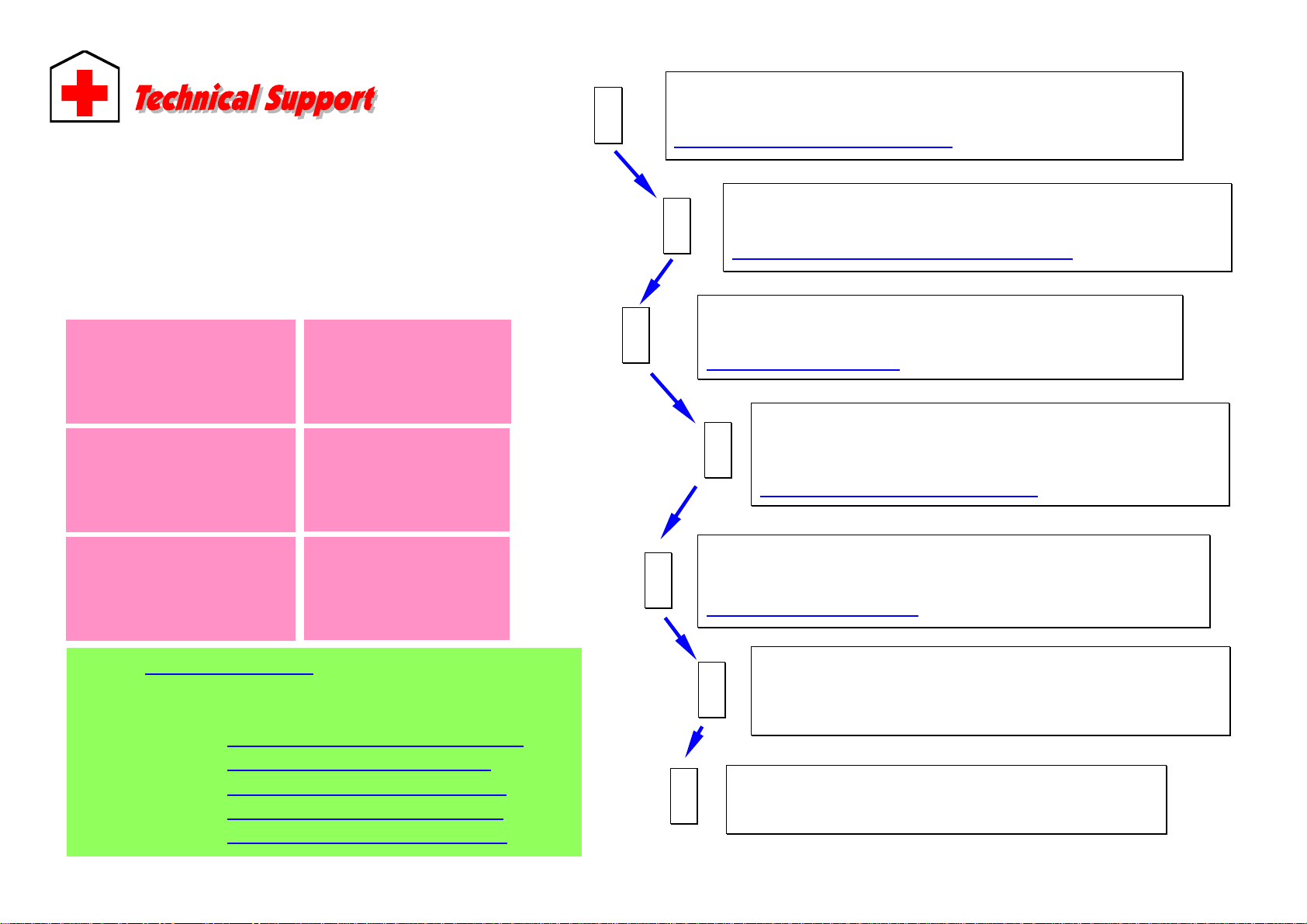
Open Technical Supporting Team
Web Site: http://www.aopen.com.tw
E-mail: Send us email by going through the contact form below.
English http://english.aopen.com.tw/tech/default.htm
Japanese http://www.aopen.co.jp/tech/default.htm
Chinese http://www.aopen.com.tw/tech/default.htm
German http://www.aopencom.de/tech/default.htm
Simplified Chinese http://www.aopen.com.cn/tech/default.htm
Pacific Rim
AOpen Inc.
Tel: 886-2-3789-5888
Fax: 886-2-3789-5899
Europe
AOpen Computer b.v.
Tel: 31-73-645-9516
Germany
AOpen Computer GmbH.
Tel: 49-1805-559191
Fax: 49-2102-157799
China
()
Tel: 86-21-6225-8622
Fax: 86-21-6225-7926
Japan
AOpen Japan Inc.
Tel: 81-048-290-1800
Fax: 81-048-290-1820
America
AOpen America Inc.
Tel: 1-510-489-8928
Fax: 1-510-489-1998
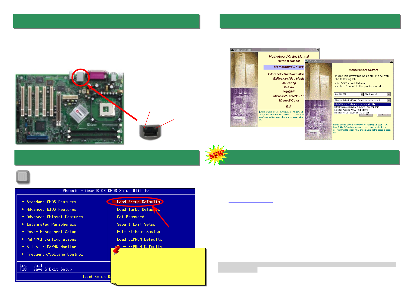
Online Manual: To download manual, please log on and then select your
preferred language. Under “Type” directory, choose “Manuals” to go to our
manual database. You can also find the manual and EIG inAOpen Bonus Pack.
http://download.aopen.com.tw/downloads
1
1
Test Report: We recommend you to choose board/card/device from the
compatibility test reports for assembling your PC. It may prevent incompatibility
problems.
http://english.aopen.com.tw/tech/report/default.htm
2
2
FAQ: Here we list problems that users often encounter and FAQ
(Frequently Asked Questions). You may select your preferred language
after log on, and may be able to find a solution to your problem.
http://club.aopen.com.tw/faq/
5
5
Download Software: After log on and having language selected, you may
get the latest updated BIOS/utility and drivers you need under “Type”
directory. In most case, newer versions of drivers and BIOS have solved
earlier bugs or compatibility problems.
http://download.aopen.com.tw/downloads
3
3
eForum: AOpen eForum is provided to discuss our products with other users, in
which your problem probably had been discussed before or will be answered.
After log on, you may select your preferred language under “Multi-language”.
http://club.aopen.com.tw/forum/
4
4
Contact Distributors/Resellers: We sell our products through resellers
and integrators. They should know your system configuration very well
and should be able to solve your problem efficiently and provide important
reference for you.
6
6
Contact Us: Please prepare detail system configuration and error
symptom before contacting us. The part number, serial number
and BIOS version are also very helpful.
7
7