PNEG-1984 Page 3 of 4
Bio-Dri II™ Air Inlet Door Assembly Instructions
Inlet Door Adjustment Instructions
1. Prior to adjustments the linear actuator must be wired up tothe PLC panel and capable of operation.
Please refer to Air Inlet Door Actuator wiring diagram. Once wired up, the two (2) dial switches on
the controls on the outside of the PLC panel can be used to operate the linear actuator. One dial
switch is used to go between Auto, Off and Hand (Manual). When in Manual mode, the other dial
switch has two (2) operating positions: Purge and Re-Cycle. When in Purge, the linear actuator will
attempt to extend a full 24'' until the internal limit switch shuts it off. When in Re-Cycle, the linear
actuator will attempt to retract until the external limit switch shown in Figure 3 on Page 4, shuts
it off.
2. Change the switch position on the outside of the PLC panel to manual Mode/Purge and let the
linear actuator extend the full 24'' until the unit comes to a stop. There will probably be a 1'' to 2''
gap remaining between the door and the framing in the Purge position. Remove the eight (8) plastic
plugson topofthe linearactuatortoprovide accesstotheallen headscrewsunderneath.Loosen all
eight(8) allenhead screwson topof theactuator with a 6mm allen wrench(P) not provided.Loosen
each screw approximately 5 complete turns.
3. Rotate the door counterclockwise slightly, until the 1'' to 2'' gap between the door and the framing
in the Purge position is closed up. As the door is rotated, the linear actuator will slide inside the
housing to the correct adjustment position. Tighten the eight (8) allen head screws securely.
Replace the eight (8) plastic plugs in the top of the linear actuator.
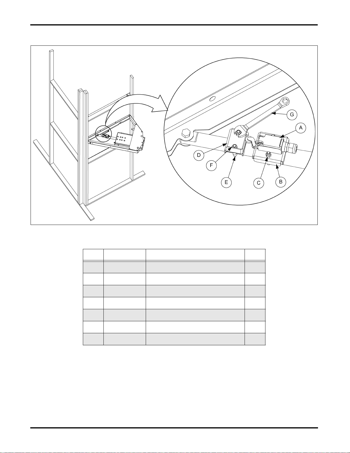
4. Refer to Figure 3 on Page 4. Change the switch position on the outside of the PLC panel to
Manual/Re-Cycle and let the linear actuator retract until the external limit switch (A) strikes the
actuator bracket (D) and the unit comes to a stop. There will probably be a 1'' to 2'' gap remaining
between the door and the framing in the Re-Cycle position. Change the switch position on the
outside of the PLC panel from manual to off.
5. Using a 1/2'' Wrench (G), loosen the nylock nuts (F) on the U-Bolt (E) and slide the actuator
bracket(D)forward towardstherodend ofthelinearactuator approximately1/4''.Tightenthe nylock
nuts (F) on the U-Bolt (E). Change the switch position on the outside of the PLC panel from Off to
Manual. The linear actuator will retract slightly until the external limit switch causes it to shut off.
Ensure that the 1'' to 2'' gapbetween the door and the framing in the Re-Cycle position is closed up.
If not, repeat this step until the door gap is closed.
6. Change the dial switches on the outside of the PLC panel to Auto/Re-Cycle. The inlet door is now
ready for normal operation. In normal operation, when the Bio-Dri II™ is not running, the inlet door
should remain in Re-Cycle position in order to keep birds and debris from entering the air mixing
chamber. When the Bio-Dri II™ is in Pre-Bake mode, Bake mode or Post Bake mode, the inlet door
should be in Re-Cycle position in order to allow the hot air to Re-Cycle through the system. The only
time the inlet door should be in Purge position, is during the 8 minute purge time at the end of the
cycle, in order to clear out deadly gas fumes and quickly cool the room down, prior to safe entry.