AP PNEG-1608 User manual

PNEG-1608
Pathogen Barrier Filter Ducts
Installation Manual
PNEG-1608
Version: 3.0
Date: 06-12-19

2PNEG-1608 Pathogen Barrier Filter Ducts
All information, illustrations, photos and specifications in this manual are based on the latest
information available at the time of publication. The right is reserved to make changes at any
time without notice.

Table of Contents
PNEG-1608 Pathogen Barrier Filter Ducts 3
Contents
Chapter 1 Safety .....................................................................................................................................................4
Safety Guidelines ...................................................................................................................................4
Cautionary Symbols Definitions .............................................................................................................5
Safety Cautions ......................................................................................................................................6
Chapter 2 Filter Duct Installation Instructions ....................................................................................................7
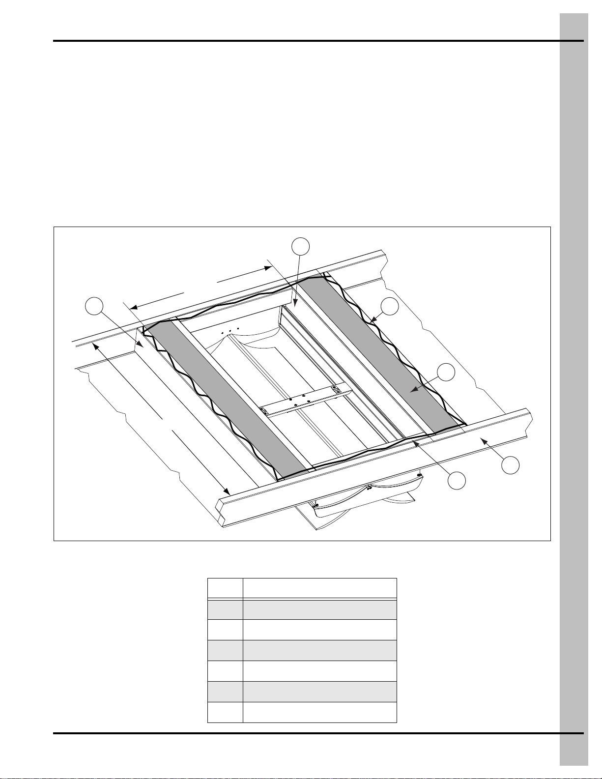
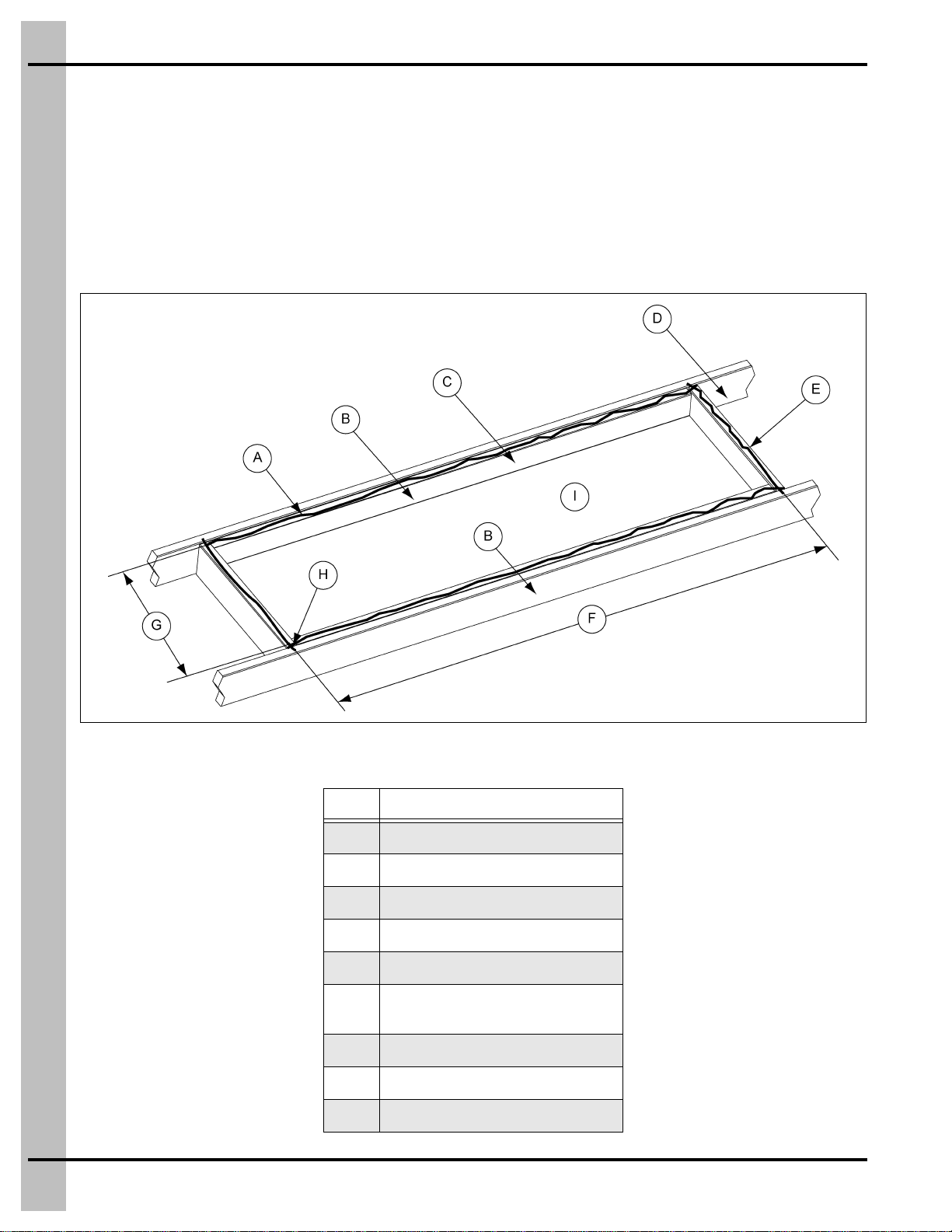
Duct Frame-Out .....................................................................................................................................7
21-1/2" Wide Top Filter Ducts ................................................................................................................8
Filter Duct Frame-Out for 6 Filters .........................................................................................................9
Filter Duct Frame-Out for 8 Filters .......................................................................................................10
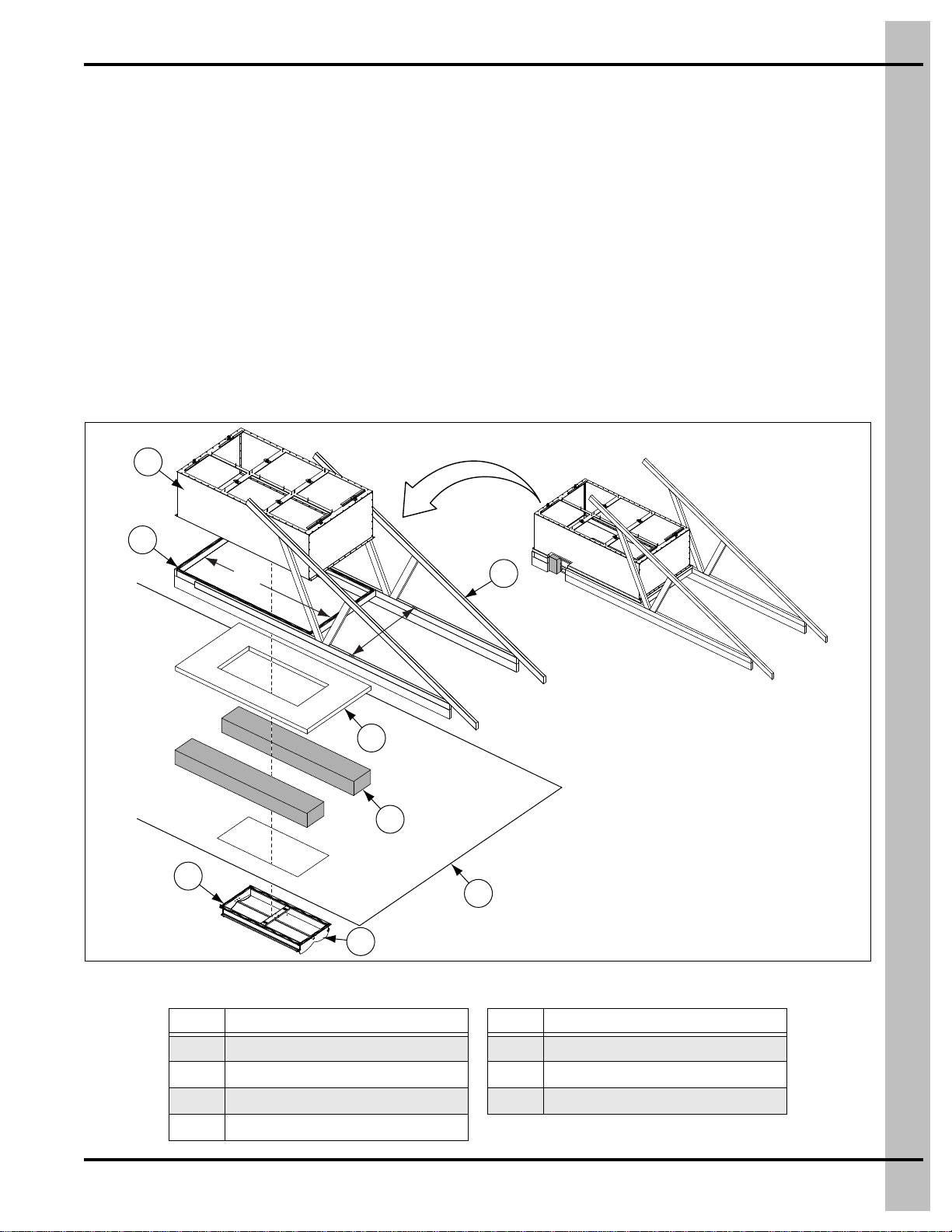
Filter Duct Assembly ............................................................................................................................11
Filter Duct Installation ...........................................................................................................................15
Filter Installation ...................................................................................................................................16
Chapter 3 Parts List .............................................................................................................................................17
Filter Duct with 2 Filters (30-0662) .......................................................................................................18
Filter Duct with 4 Filters (30-0664) .......................................................................................................19
Filter Duct with 6 Filters (30-0666) .......................................................................................................20
Filter Duct, Top Load - 6 Pathogen Barrier Filters (30-1000) ...............................................................21
Filter Duct, Top Load - 8 Pathogen Barrier Filter (30-1011) .................................................................22
Chapter 4 Warranty ..............................................................................................................................................23

4PNEG-1608 Pathogen Barrier Filter Ducts
1. Safety
Safety Guidelines
Safety guidelines shall be followed at all times. This manual is written to help you understand safe
operating procedures and problems that can be encountered by the operator and other personnel when
using this equipment. Read and save these instructions.
As owner or operator, you are responsible for understanding the requirements, hazards, and precautions
that exist and to inform others as required. Unqualified persons must stay out of the work area at all times.
Alterations shall not be made to the equipment. Alterations can produce dangerous situations resulting in
SERIOUS INJURY or DEATH.
This equipment shall be installed in accordance with the current installation codes and applicable
regulations, which must be carefully followed in all cases. Authorities having jurisdiction shall be consulted
before installations are made.
When necessary, you shall consider the installation location relative to electrical, fuel and water utilities.
Personnel operating or working around equipment shall read this manual. This manual shall be delivered
with equipment to its owner. Failure to read this manual and its safety instructions is a misuse of the
equipment.
ST-0001-4

1. Safety
PNEG-1608 Pathogen Barrier Filter Ducts 5
Cautionary Symbols Definitions
Cautionary symbols appear in this manual and on product decals. The symbols alert the user of potential
safety hazards, prohibited activities and mandatory actions. To help you recognize this information, we
use the symbols that are defined below.
DANGER
WARNING
CAUTION
NOTICE
This symbol indicates an imminently hazardous situation
which, if not avoided, will result in serious injury or death.
This symbol indicates a potentially hazardous situation
which, if not avoided, can result in serious injury or death.
This symbol indicates a potentially hazardous situation which,
if not avoided, can result in minor or moderate injury.
This symbol is used to address practices not related to
personal injury.
This symbol indicates a general hazard.
This symbol indicates a prohibited activity.
This symbol indicates a mandatory action.
ST-0005-2

1. Safety
6PNEG-1608 Pathogen Barrier Filter Ducts
Safety Cautions
Use Personal Protective Equipment
Eye
Protection
Hearing
Protection
Hand
Protection
Head
Protection
Respiratory
Protection Foot
Protection
Fall
Protection
• Use appropriate personal protective equipment:
• Wear clothing appropriate to the job.
• Remove all jewelry.
• Tie long hair up and back.
ST-0004-1
Follow Safety Instructions
• Carefully read all safety messages in this manual and
safety signs on your machine. Keep signs in good
condition. Replace missing or damaged safety signs. Be
sure new equipment components and repair parts include
the current safety signs. Replacement safety signs are
available from the manufacturer.
• Learn how to operate the machine and how to use controls
properly. Do not let anyone operate without instruction.
• If you do not understand any part of this manual or need
assistance, contact your dealer.
ST-0002-1

PNEG-1608 Pathogen Barrier Filter Ducts 7
2. Filter Duct Installation Instructions
Duct Frame-Out
1. Remove the existing insulation barrier.
2. Add a 46-1/2" stringer (A) to either side of the existing inlet frame-out (B). The inside dimensions of
the filter duct frame-out should be 27-1/2" x 43-1/2".
3. Add 2" x 4" filler boards (D) against the inlet side of both lower truss cords (E), flush to the top (attic)
side. (See Figure 2A.)
4. Install insulation (F) into the dead space between the frame-out and filter duct.
5. Apply caulk (C) over the stringers (A) and the filler boards (D).
6. Cover the insulation (F) with the plywood.
Figure 2A
Ref # Description
AFilter Duct Stringer 46-1/2" Long
B Existing Frame-Out
CCaulk
D 2" x 4" Filler
ETruss
FInsulation
27-1/2"
43-1/2"
A
B
C
F
D
E

2. Filter Duct Installation Instructions
8PNEG-1608 Pathogen Barrier Filter Ducts
21-1/2" Wide Top Filter Ducts
1. Remove the existing insulation barrier.
2. The inside dimensions of the filter duct frame-out should be 75" x 19-1/2" for the 3 filter duct and
50" x 19-1/2" for the 2 filter duct (F).
NOTE: It is recommended to center the filter duct after the inlet.
3. Add 2" x 4" filler boards (E) against the inlet side of both lower truss cords (D), flush to the top (attic)
side. (See Figure 2B.)
Figure 2B
Ref # Description
ACaulk
B Existing Frame-Out
CFilter Duct Stringer 46-1/2" Long
DTruss
E2" x 4" Filler
F3 Filter (30-2403) = 75"
2 Filter (30-2402) = 50"
G19-1/2" Inside
H Overlap caulk for a good seal.
I24" On center trussing.

2. Filter Duct Installation Instructions
PNEG-1608 Pathogen Barrier Filter Ducts 9
Filter Duct Frame-Out for 6 Filters
1. Frame out the area for the duct (A) between the truss cords, making sure that the frame (D) is flush
with the top. (See Figure 2C.)
2. Install the attic vent (G) according to the attic vent installation instructions. (See Figure 2A on Page 7.)
3. Fill in the area around the hole cut for the vent (G) with insulation (C).
4. Cut a sheet of plywood (B) for XX" x 48-3/4", that should fit on the top of the truss frames (D).
NOTE: Width 48-3/4" is measured from the middle of truss to truss and the length XX" is based
on the customer.
5. Cut a hole in the plywood (B) the same dimensions as the vent (G) and at the same location within
the truss frame (D), so that the hole aligns with the vent (G) when the plywood (B) is installed.
6. Apply caulking (F) along the top of the frames (D) where the plywood (B) will be installed and install
the plywood (B).
7. Apply caulking (F) on top of the plywood (B) where the duct (A) will be installed and install the duct (A).
Figure 2C Filter Duct Frame-Out - 6 Filters
Ref # Description Ref # Description
AFilter Duct ECeiling
B Plywood F Caulking
CInsulation GAttic Vent
DFrame-Out
Assembly view
78-1/4"
48-3/4"
D
B
C
E
G
F
F
A

2. Filter Duct Installation Instructions
10 PNEG-1608 Pathogen Barrier Filter Ducts
Filter Duct Frame-Out for 8 Filters
1. Frame out the area for the duct (A) between the truss cords, making sure that the frame (D) is flush
with the top. (See Figure 2D.)
2. Install the attic vent (G) according to the attic vent installation instructions.(See Figure 2A on Page 7.)
3. Fill in the area around the hole cut for the vent (G) with insulation (C).
4. Cut a sheet of plywood (B) for XX" x 48-3/4", that should fit on the top of the truss frames (D).
NOTE: Width 48-3/4" is measured from the middle of truss to truss and the length XX" is based
on the customer.
5. Cut a hole in the plywood (B) the same dimensions as the vent (G) and at the same location within
the truss frame (D), so that the hole aligns with the vent (G) when the plywood (B) is installed.
6. Apply caulking (F) along the top of the frames (D) where the plywood (B) will be installed and install
the plywood (B).
7. Apply caulking (F) on top of the plywood (B) where the duct (A) will be installed and install the duct (A).
Figure 2D Filter Duct Frame-Out - 8 Filters
Ref # Description Ref # Description
AFilter Duct ECeiling
B Plywood F Caulking
CInsulation GAttic Vent
DFrame-out
A
D
F
B
C
E
F
G
Assembly view
104"
48-3/4"

2. Filter Duct Installation Instructions
PNEG-1608 Pathogen Barrier Filter Ducts 11
Filter Duct Assembly
1. Apply one strip of caulk (D) along the top and side flanges of the end panels (C) to the inside of the
holes as shown in Figure 2E.
NOTE: Ensure the full flange length is covered.
2. Continue to assemble the filter (B) and end panels (C) with the screws (E) provided.
3. Apply one strip of caulk (D) completely around the top flange of the filter panels (B).
4. Apply extra strips of caulk (D) diagonally across the corner seam of the filter panels (B) and
end panels (C).
5. Continue to assemble the top panel (A) with screws (E) provided.
Figure 2E
Ref # Description
ATop Panel
B Top Filter Panel
CEnd Panel
DCaulk
EScrews
A
B
DC
E

2. Filter Duct Installation Instructions
12 PNEG-1608 Pathogen Barrier Filter Ducts
Figure 2F Filter Duct with 2 Filters (30-0662) Exploded View
Figure 2G Filter Duct with 4 Filters (30-0664) Exploded View
Ref # Description Ref # Description
ATop Panel EScrews
B Top Filter Panel F Side Panel
CEnd Panel GRound Knurled Knob
B
F
C
EA
B
E
C
G

2. Filter Duct Installation Instructions
PNEG-1608 Pathogen Barrier Filter Ducts 13
Figure 2H Filter Duct with 6 Filters (30-0666) Exploded View
Ref # Description
BTop Filter Panel
C End Panel
EScrews
G Round Knurled Knob
HSide Filter Panel
G
EB
H
C
C
H

2. Filter Duct Installation Instructions
14 PNEG-1608 Pathogen Barrier Filter Ducts
Figure 2I 2 Filter Duct (30-2402) Exploded View
Figure 2J 3 Filter Duct (30-2403) Exploded View
Ref # Description
BTop Filter Panel
C End Panel
FSide Panel

2. Filter Duct Installation Instructions
PNEG-1608 Pathogen Barrier Filter Ducts 15
Filter Duct Installation
1. Seal all inside edges of the wood frame-out (B) with silicon caulk. (See Figure 2A on Page 7.)
2. Apply an ample amount of silicon caulk around the top side of the filter duct frame-out.
3. Set the filter duct (A) on the frame-out (B) and attach through the flanges.
NOTE: Ensure there are no gaps or leaks at any seam.
Figure 2K
Ref # Description
AFilter Duct
B Frame-Out
A
B

2. Filter Duct Installation Instructions
16 PNEG-1608 Pathogen Barrier Filter Ducts
Filter Installation
1. Install the filter retaining bracket (30-0667) at the bottom of the filter openings using the knobs
(S-9424) provided.
2. Place the L6/L9 barrier filters through theopening(s) allowing themto rest on thebottom filter retainer
bracket(s). Note the direction of the clips on the filters. (See Figure 2L.)
3. Install the top filter retaining bracket against the top portion of the filters for each opening.
NOTE: Filter retaining brackets may need to be adjusted to ensure the duct flanges extend over
the filter flanges.
Figure 2L

PNEG-1608 Pathogen Barrier Filter Ducts 17
3. Parts List
1. Filter Duct with 2 Filters (30-0662) - (See Page 18.)
2. Filter Duct with 4 Filters (30-0664) - (See Page 19.)
3. Filter Duct with 6 Filters (30-0666) - (See Page 20.)
4. Filter Duct, Top Load - 6 Pathogen Barrier Filters (30-1000) - (See Page 21.)
5. Filter Duct, Top Load - 8 Pathogen Barrier Filter (30-1011) - (See Page 22.)

3. Parts List
18 PNEG-1608 Pathogen Barrier Filter Ducts
Filter Duct with 2 Filters (30-0662)
Ref # Part # Description Qty
130-0660 Side Panel 2
2 30-0663 End Panel 2
330-0671A Top Filter Panel 1
4 30-0655 24" x 24" M14/L6 Sealed Pathogen Barrier With Gasket on Header 1
5S-9423 Screw, SMSAB #12 x 5/8" HWH ZN 65
6 30-0667 Filter Retaining Bracket Assembly 4
7S-9424 Round Knurled Knob - 1/4"-20 x 1/2" SS 12
8 30-0656 20" x 24" M14/L6 Sealed Pathogen Barrier with Gasket on Header 1
930-0574 24" x 24" Aeropleat Pre-Filter 2" Thick 1
10 30-0575 20" x 24" Aeropleat Pre-Filter 2" Thick 1
11 30-0659 2" Pre-Filter Clip 8

3. Parts List
PNEG-1608 Pathogen Barrier Filter Ducts 19
Filter Duct with 4 Filters (30-0664)
Ref # Part # Description Qty
130-0545A Filter Panel Assembly 2
2 30-0546 Air Chamber Side Panel 2
330-0547 Top Filter Panel 1
4 30-0655 24" x 24" M14/L6 Sealed Pathogen Barrier with Gasket on Header 2
5S-9423 Screw, SMSAB #12 x 5/8" HWH ZN7 72
6 30-0667 Filter Retaining Bracket Assembly 4
7S-9424 Round Knurled Knob - 1/4"-20 x 1/2" SS 12
8 30-0656 20" x 24" M14/L6 Sealed Pathogen Barrier with Gasket on Header 2
930-0574 24" x 24" Aeropleat Pre-Filter 2" Thick 2
10 30-0575 20" x 24" Aeropleat Pre-Filter 2" Thick 2
11 30-0659 2" Pre-Filter Clip 16

3. Parts List
20 PNEG-1608 Pathogen Barrier Filter Ducts
Filter Duct with 6 Filters (30-0666)
Ref # Part # Description Qty
130-0565A Filter Panel Assembly 2
2 30-0566 Air Chamber Side Panel 2
330-0573A Top Panel Assembly 1
4 30-0655 24" x 24" M14/L6 Sealed Pathogen Barrier with Gasket on Header 3
5S-9424 Round Knurled Knob - 1/4"-20 x 1/2" SS 18
6 S-9423 Screw, SMSAB #12 x 5/8" HWH ZN 88
730-0550 High Capacity V-Style Filter 95% Dop Merv 16, 24" x 24" 3
8 30-0656 20" x 24" M14/L6 Sealed Pathogen Barrier with Gasket on Header 3
930-0574 24" x 24" Aeropleat Pre-Filter 2" Thick 3
10 30-0575 20" x 24" Aeropleat Pre-Filter 2" Thick 3
11 30-0659 2" Pre-Filter Clip 24
Table of contents
Other AP Industrial Equipment manuals
Popular Industrial Equipment manuals by other brands

Heidolph
Heidolph Hei-VAP Industrial operating manual

Carlisle
Carlisle IntelliSpray IS30 user manual

ABB
ABB HT571230 Operation manual

PCB Piezotronics
PCB Piezotronics ICP W353B31 Installation and operating manual

Jet
Jet JTM-949EVS4 Operating instructions and parts manual

Simplex
Simplex LBD Series Technical manual