Chore-Time ULTRAFLO Cage Free Setup guide

For additional parts and information, contact your nearest Chore-Time distributor or representative.
Find your nearest distributor at: www.choretime.com/contacts
CTB, Inc.
PO Box 2000
Milford, Indiana 46542-2000 USA
Phone (574) 658-4101
Email: choretime@choretime.com
Internet: www.choretime.com
Cage Free ULTRAFLO®
Feeding System
MC2507AJune 2022
Installation and Operators Manual
Installation and Operators Manual

Contents
Topic Page
MC2507A 2
Chore Time Limited Warranty . . . . . . . . . . . . . . . . . . . . . . . . . . . . . . . . . . . . . . . . . . . . . . . . . . . . . . . . . . . 3
Introduction. . . . . . . . . . . . . . . . . . . . . . . . . . . . . . . . . . . . . . . . . . . . . . . . . . . . . . . . . . . . . . . . . . . . . 4
Safety Information . . . . . . . . . . . . . . . . . . . . . . . . . . . . . . . . . . . . . . . . . . . . . . . . . . . . . . . . . . . . . . . . . . . . 5
Follow Safety Instructions . . . . . . . . . . . . . . . . . . . . . . . . . . . . . . . . . . . . . . . . . . . . . . . . . . . . . . . . . . . . . . 5
Decal Descriptions . . . . . . . . . . . . . . . . . . . . . . . . . . . . . . . . . . . . . . . . . . . . . . . . . . . . . . . . . . . . . . . . . . . . 5
DANGER: Moving Parts . . . . . . . . . . . . . . . . . . . . . . . . . . . . . . . . . . . . . . . . . . . . . . . . . . . . . . . . . . . 5
DANGER: Electrical Hazard . . . . . . . . . . . . . . . . . . . . . . . . . . . . . . . . . . . . . . . . . . . . . . . . . . . . . . . . 5
Planning. . . . . . . . . . . . . . . . . . . . . . . . . . . . . . . . . . . . . . . . . . . . . . . . . . . . . . . . . . . . . . . . . . . . . . . . 6
Recommended Power Unit Locations . . . . . . . . . . . . . . . . . . . . . . . . . . . . . . . . . . . . . . . . . . . . . . . . . . . . . 6
Feeder Loop Layout . . . . . . . . . . . . . . . . . . . . . . . . . . . . . . . . . . . . . . . . . . . . . . . . . . . . . . . . . . . . . . . . . . . 7
Trough Lengths . . . . . . . . . . . . . . . . . . . . . . . . . . . . . . . . . . . . . . . . . . . . . . . . . . . . . . . . . . . . . . . . . . . 7
Loop Width . . . . . . . . . . . . . . . . . . . . . . . . . . . . . . . . . . . . . . . . . . . . . . . . . . . . . . . . . . . . . . . . . . . . . . 7
Installation. . . . . . . . . . . . . . . . . . . . . . . . . . . . . . . . . . . . . . . . . . . . . . . . . . . . . . . . . . . . . . . . . . . . . . 8
Suspended and Stand Feed Loop Systems Installation. . . . . . . . . . . . . . . . . . . . . . . . . . . . . . . . . . . . . . . . . 8
Suspended Systems . . . . . . . . . . . . . . . . . . . . . . . . . . . . . . . . . . . . . . . . . . . . . . . . . . . . . . . . . . . . . . . . 8
. . . . . . . . . . . . . . . . . . . . . . . . . . . . . . . . . . . . . . . . . . . . . . . . . . . . . . . . . . . . . . . . . . . . . . . . . . . . . . . . 8
Stand Systems . . . . . . . . . . . . . . . . . . . . . . . . . . . . . . . . . . . . . . . . . . . . . . . . . . . . . . . . . . . . . . . . . . . . 8
Power Lift Winch Installation . . . . . . . . . . . . . . . . . . . . . . . . . . . . . . . . . . . . . . . . . . . . . . . . . . . . . . . . 9
Attaching Winch Support to Trusses. . . . . . . . . . . . . . . . . . . . . . . . . . . . . . . . . . . . . . . . . . . . . . . . . . .10
Main Winch Cable. . . . . . . . . . . . . . . . . . . . . . . . . . . . . . . . . . . . . . . . . . . . . . . . . . . . . . . . . . . . . . . . .11
Cable Routing at Winch. . . . . . . . . . . . . . . . . . . . . . . . . . . . . . . . . . . . . . . . . . . . . . . . . . . . . . . . . . . . .12
Wrapping Cable on Winch Drum . . . . . . . . . . . . . . . . . . . . . . . . . . . . . . . . . . . . . . . . . . . . . . . . . . . . .12
Ceiling Hook Installation. . . . . . . . . . . . . . . . . . . . . . . . . . . . . . . . . . . . . . . . . . . . . . . . . . . . . . . . . . . .12
Suspension Drop Lines . . . . . . . . . . . . . . . . . . . . . . . . . . . . . . . . . . . . . . . . . . . . . . . . . . . . . . . . . . . . .13
Suspension Drop Line Installation. . . . . . . . . . . . . . . . . . . . . . . . . . . . . . . . . . . . . . . . . . . . . . . . . . . . .16
Loop Components Installation . . . . . . . . . . . . . . . . . . . . . . . . . . . . . . . . . . . . . . . . . . . . . . . . . . . . . . . . . . .18
Intake Cup and Elbows Installation. . . . . . . . . . . . . . . . . . . . . . . . . . . . . . . . . . . . . . . . . . . . . . . . . . . .18
Clean-Out Installation . . . . . . . . . . . . . . . . . . . . . . . . . . . . . . . . . . . . . . . . . . . . . . . . . . . . . . . . . . . . . .18
Trough, Trough Hangers, and Perch Tubes Installation . . . . . . . . . . . . . . . . . . . . . . . . . . . . . . . . . . . .19
3 Perch Feeder Supports, Perch Tubes, & Angle Braces (For resting on Stands). . . . . . . . . . . . . . . . .21
Connecting Trough Sections together and Trough End Caps . . . . . . . . . . . . . . . . . . . . . . . . . . . . . . . .22
Trough Section End Caps . . . . . . . . . . . . . . . . . . . . . . . . . . . . . . . . . . . . . . . . . . . . . . . . . . . . . . . . . . .22
Power Unit Base Installation . . . . . . . . . . . . . . . . . . . . . . . . . . . . . . . . . . . . . . . . . . . . . . . . . . . . . . . . .23
ULTRAFLO® Auger Installation . . . . . . . . . . . . . . . . . . . . . . . . . . . . . . . . . . . . . . . . . . . . . . . . . . . . .25
Auger Connector Installation. . . . . . . . . . . . . . . . . . . . . . . . . . . . . . . . . . . . . . . . . . . . . . . . . . . . . . . . .26
Power Unit Installation . . . . . . . . . . . . . . . . . . . . . . . . . . . . . . . . . . . . . . . . . . . . . . . . . . . . . . . . . . . . .27
Suspending the System . . . . . . . . . . . . . . . . . . . . . . . . . . . . . . . . . . . . . . . . . . . . . . . . . . . . . . . . . . . . . . . . .30
Trough Hanger Suspension . . . . . . . . . . . . . . . . . . . . . . . . . . . . . . . . . . . . . . . . . . . . . . . . . . . . . . . . . .30
Suspension at Elbows . . . . . . . . . . . . . . . . . . . . . . . . . . . . . . . . . . . . . . . . . . . . . . . . . . . . . . . . . . . . . .30
Suspension at Elbows . . . . . . . . . . . . . . . . . . . . . . . . . . . . . . . . . . . . . . . . . . . . . . . . . . . . . . . . . . . . . .31
Suspension at Power Unit . . . . . . . . . . . . . . . . . . . . . . . . . . . . . . . . . . . . . . . . . . . . . . . . . . . . . . . . . . .32
Static Chain (Not Supplied). . . . . . . . . . . . . . . . . . . . . . . . . . . . . . . . . . . . . . . . . . . . . . . . . . . . . . . . . .34
Troubleshooting . . . . . . . . . . . . . . . . . . . . . . . . . . . . . . . . . . . . . . . . . . . . . . . . . . . . . . . . . . . . . . . . 36
Parts Listing . . . . . . . . . . . . . . . . . . . . . . . . . . . . . . . . . . . . . . . . . . . . . . . . . . . . . . . . . . . . . . . . . . . 38
ULTRAFLO® Cage Free Feeder Line Components . . . . . . . . . . . . . . . . . . . . . . . . . . . . . . . . . . . . . . . . . .38
Part Numbers . . . . . . . . . . . . . . . . . . . . . . . . . . . . . . . . . . . . . . . . . . . . . . . . . . . . . . . . . . . . . . . . . . . . . . . .39
Clean-Out Assembly (Part No. 13405) and Lock Kit (Part No. 57375). . . . . . . . . . . . . . . . . . . . . . . . . . . .41
Power Unit and Driver Assembly . . . . . . . . . . . . . . . . . . . . . . . . . . . . . . . . . . . . . . . . . . . . . . . . . . . . . . . . .42
Miscellaneous Suspension Components. . . . . . . . . . . . . . . . . . . . . . . . . . . . . . . . . . . . . . . . . . . . . . . . . . . .44
Winch (Part No. 47687) . . . . . . . . . . . . . . . . . . . . . . . . . . . . . . . . . . . . . . . . . . . . . . . . . . . . . . . . . . . . . . . .45

3
MC2507A
Chore Time Limited Warranty
Chore-Time Group, a division of CTB, Inc. (“Chore-Time”) warrants the new CHORE-TIME Floor Feeding Parts
manufactured by Chore-Time to be free from defects in material or workmanship under normal usage and conditions, for
One (1) year from the date of installation by the original purchaser (“Warranty”). Chore-Time provides for an extension of
the aforementioned Warranty period (“Extended Warranty Period”) with respect to certain Product parts (“Component
Part”) as set forth in the table below. If such a defect is determined by Chore-Time to exist within the applicable period,
Chore-Time will, at its option, (a) repair the Product or Component Part free of charge, F.O.B. the factory of manufacture or
(b) replace the Product or Component Part free of charge, F.O.B. the factory of manufacture. This Warranty is not
transferable, and applies only to the original purchaser of the Product.
CONDITIONS AND LIMITATIONS
THIS WARRANTY CONSTITUTES CHORE-TIME’S ENTIRE AND SOLE WARRANTY AND CHORE-TIME
EXPRESSLY DISCLAIMS ANY AND ALL OTHER WARRANTIES, INCLUDING, BUT NOT LIMITED TO,
EXPRESS AND IMPLIED WARRANTIES, INCLUDING, WITHOUT LIMITATION, WARRANTIES AS TO
MERCHANTABILITY OR FITNESS FOR PARTICULAR PURPOSES. CHORE-TIME shall not be liable for any direct,
indirect, incidental, consequential or special damages which any purchaser may suffer or claim to suffer as a result of any
defect in the Product. Consequential or Special Damages as used herein include, but are not limited to, lost or damaged
products or goods, costs of transportation, lost sales, lost orders, lost income, increased overhead, labor and incidental costs,
and operational inefficiencies. Some jurisdictions prohibit limitations on implied warranties and/or the exclusion or
limitation of such damages, so these limitations and exclusions may not apply to you. This warranty gives the original
purchaser specific legal rights. You may also have other rights based upon your specific jurisdiction.
Compliance with federal, state and local rules which apply to the location, installation and use of the Product are the
responsibility of the original purchaser, and CHORE-TIME shall not be liable for any damages which may result from non-
compliance with such rules.
The following circumstances shall render this Warranty void:
• Modifications made to the Product not specifically delineated in the Product manual.
• Product not installed and/or operated in accordance with the instructions published by the CHORE-TIME.
• All components of the Product are not original equipment supplied by CHORE-TIME.
• Product was not purchased from and/or installed by a CHORE-TIME authorized distributor or certified representative.
• Product experienced malfunction or failure resulting from misuse, abuse, mismanagement, negligence, alteration, acci-
dent, or lack of proper maintenance, or from lightning strikes, electrical power surges or interruption of electricity.
• Product experienced corrosion, material deterioration and/or equipment malfunction caused by or consistent with the
application of chemicals, minerals, sediments or other foreign elements.
• Product was used for any purpose other than for the care of poultry and livestock.
The Warranty and Extended Warranty may only be modified in writing by an officer of CHORE-TIME. CHORE-TIME
shall have no obligation or responsibility for any representations or warranties made by or on behalf of any distributor,
dealer, agent or certified representative.
Effective: April, 2014
CTB, Inc.
PO Box 2000
Milford, Indiana 46542-2000 USA
Phone (574) 658-4101
Email: choretime@choretime.com
Internet: www.choretime.com
Component Part Extended Warranty Period
RXL Fan (except motors and bearings) Three (3) Years
TURBO® Fan (except motors and bearings) Three (3) Years
TURBO® Fan fiberglass housing, polyethylene cone, and cast aluminum blade. Lifetime of Product
TURBO® fan motor and bearings. Two (2) Years
Chore-Time® Poultry Feeder Pan Three (3) Years
Chore-Time® Rotating Centerless Augers (except where used in applications involving high
moisture feed stuffs exceeding 17%)
Ten (10) Years
Chore-Time Steel Auger Tubes Ten (10) Years
ULTRAFLO® Breeder Feeding System auger and feed trough. Five (5) Years
ULTRAPAN® Feeding System augers . Five (5) Years

Introduction
4MC2507A
Chore-Time has designed the ULTRAFLO®Cage Free Feeding System to feed Poultry Livestock within a
Structured and/or Floor feeding environment.
Feed is delivered to the Intake Cups by a Chore-Time FLEX-AUGER System. Feed is drawn out of the Intake Cups
by the ULTRAFLO®Floor Feeder Auger. Chore-Time does not recommend feeding pellets with the ULTRAFLO®
system.
The system is designed to feed 4 birds per foot (13 birds per meter) of trough. The feeder will deliver feed at a rate
of 80 feet (24.4 m) per minute. The Feeder Auger will hold approximately .55 pounds of feed per foot (.82 kg of
feed per meter).
The Auger serves as a stirring devise as it delivers feed around the loop.
The ULTRAFLO®Feeder uses the Chore-Tronics 3 Control. The fill system and feeder lines are controlled by
separate channels. The length of run time will be set when the system is first operated. The length of run time is
adjustable and may be changed. The Control also allows settings for number of feedings per day.
Introduction
Introduction
5
MC2507A
Safety Information
Caution, Warning and Danger Decals have been placed on the equipment to warn of potentially dangerous
situations. Care should be taken to keep this information intact and easy to read at all times. Replace missing or
damaged safety decals immediately.
Safety–Alert Symbol
This is a safety–alert symbol. When you see this symbol on your equipment, be alert to the potential
for personal injury. This equipment is designed to be installed and operated as safely as
possible...however, hazards do exist.
Understanding Signal Words
Signal words are used in conjunction with the safety–alert symbol to identify the severity of the warning.
DANGER indicates an imminently hazardous situation which, if not avoided, WILL result in death or
serious injury.
WARNING indicates a potentially hazardous situation which, if not avoided, COULD result in death or
serious injury.
CAUTION indicates a hazardous situation which, if not avoided, MAY result in minor or moderate
injury.
Follow Safety Instructions
Carefully read all safety messages in this manual and on your equipment safety signs. Follow recommended
precautions and safe operating practices.
Keep safety signs in good condition. Replace missing or damaged safety signs.
Caution!
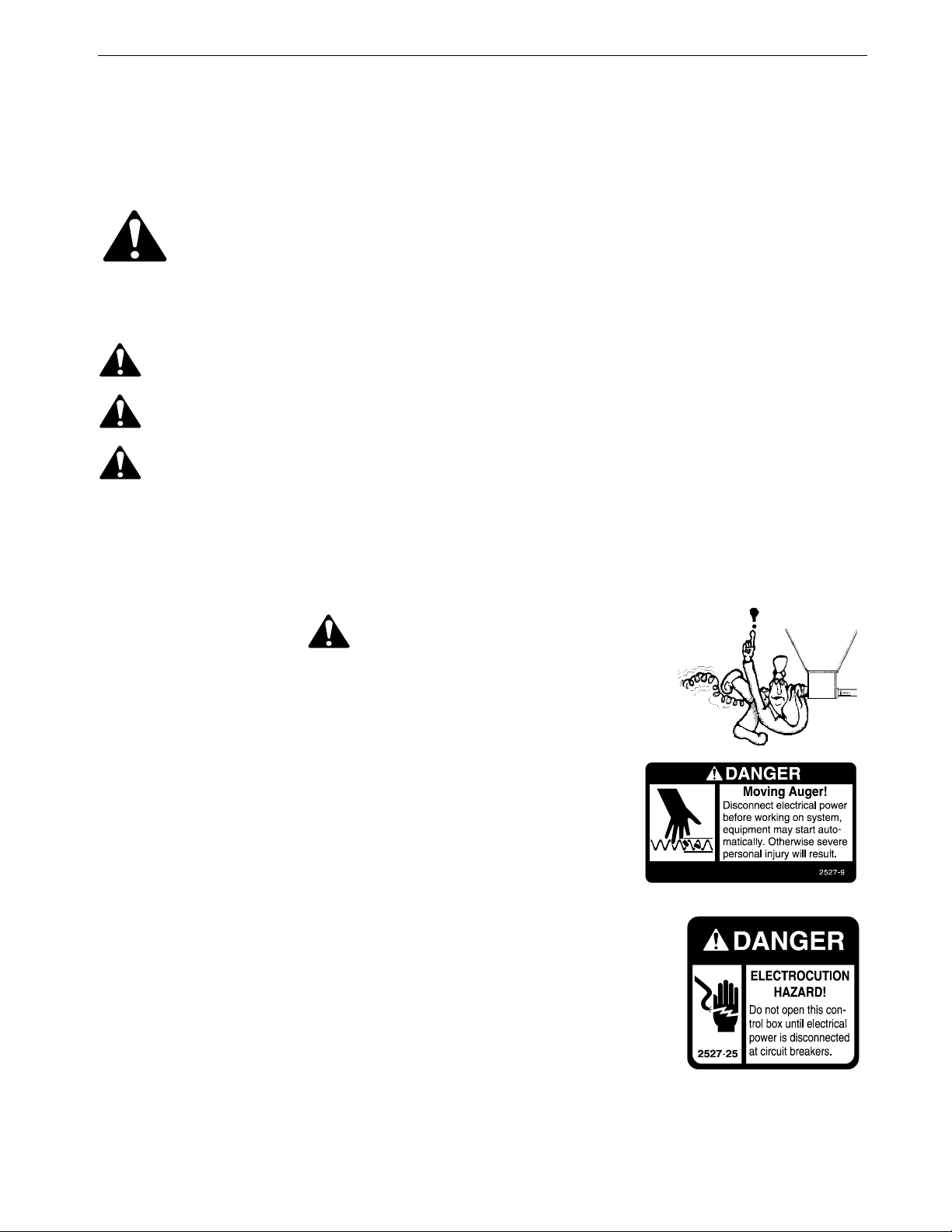
Decal Descriptions
DANGER: Moving Parts
Disconnect electrical power before working on system, equipment may
start automatically. Otherwise personal injury will result.
Severe personal injury will result if the equipment is operated without
covers properly installed.
DANGER: Electrical Hazard
Disconnect electrical power before inspecting or servicing equipment unless
maintenance instructions specifically state otherwise.
Ground all electrical equipment for safety.
All electrical wiring must be done by a qualified electrician in accordance with
local and national electric codes.
Ground all non-current carrying metal parts to guard against electrical shock.
Electrical disconnects and over current protection are not supplied with the equipment.
Use caution when working with the Auger--springing
auger may cause personal injury.

Planning
6MC2507A
Carefully planning the system prior to beginning the installation will save time and effort.
Recommended Power Unit Locations
See Figure 2 for Power Unit locations.
Houses up to 440’ (134 m)
Two Power Units are recommended. These Power Units should be located at the center of the loop and
directly across from one another for ease of wiring. (See Figure 2, page 7)
Houses 441’ to 750’ (135m to 229 m)
Four Power Units are recommended. These Power Units should also be spaced evenly around the system.
To determine the proper placement of the power units, add the total length of the system, including 4’ (1.2
m) for each 90 degree elbow, and divide by 4. This will give an approximate distance between Power
Units, round up or down to the nearest suspension drop line. The Power Units should be evenly spaced
directly across from each other in the system. The Power Units should be placed in positions (See
Figure 2, page 7).
Planning
Center of Loop
Minimum 50’ [15.2 m]
Power Unit to Elbow Distance
Minimum 50’ [15.2 m]
Power Unit to Elbows
Figure 1.Power Unit Locations
Two Power Unit System
Up to 440 feet (134 m)
Four Power Unit System
441’ to 750’ (135m to 229 m)

Planning
7
MC2507A
Feeder Loop Layout
Adequate overhead structure must be provided to support the weight of the Feeder, Birds, Power Units, etc.
1.Suspensions Drop Lines should always line up with Trusses. If attaching drop lines to Trusses is impossible,
adequate load baring structure must be provided.
2.Stagger Drop Lines as shown. When Staggered, Drops are spaced 4’ [1.2 m] or 5’ [1.5 m] apart to coincide
with 8’ [2.4 m] or 10’ [3 m] Truss Spacing.
3.Each 90° Elbow needs its own Suspension Drop.
4.Extra Drop Lines need to be added to support Power Units.
Trough Lengths
Troughs are available in 8’ [2.4m] and 10’ [3m] lengths. This allows for Troughs to line up with Trusses.
1.Plan so that Trusses line up with suspension points near Trough Joints. (See Figure 2.)
Loop Width
The ULTRAFLO®Feeder loop is 44" [1.12 m] wide (minimum). Additional width may be achieved by adding
a straight section of tube between Elbows.
Alternate Drop Lines every 4’ [1.2m] or 5’
[1.5m] (Depends on truss spacings)
Item Description
1 Suspension Drop Line
2 Auger Travel
3 44" [1.12 m] wide (minimum)
4 4’ [1.2 m] or 5’ [1.5 m]
5Bin
6Scale
7 Screener
8 Intake Cup
9 Clean-out
10 Suspension Drop Line at Elbows
to prevent Elbow sagging
3
Figure 2.Feeder Loop Layout
6
8
To next loop
1
5
Trough Joints
Approximately 6"
[15.2 cm] from
Truss centers
1
10
10
10
7
4
11
1
1
9
1
1
1

Installation
8MC2507A
F
Suspended and Stand Feed Loop Systems Installation
The feeder line suspension is a vital part of your feeding system. Take time to thoroughly plan the system to insure
proper operation.
Suspended Systems
Suspended ULTRAFLO® Floor Feeders typically utilize two types of suspension:
Winch-able: A winch-able cable system for raising and lowering the empty feeder loops during
installation and house clean-out.
Static Chain Suspension: A Static Chain Suspension used to support the load of the Feeding System,
feed and birds during regular operation.
1.Suspension Systems have a maximum length of 120’ [36.5 m].
2.A single Winch and suspension system is required to raise and lower the entire Feed Loop.
3.Double Back Pulleys required at the Winch.
4.Special Pulley Assemblies are required to route the Cable.
5.A suspension line is required on each side of any Power Unit to support the weight adequately.
6.A suspension line is required on each side of an Intake Cup to support the weight adequately.
Determine where the feeder line is to be installed. Mark a straight line on the ceiling or rafters the full length of
the feeder line. Use a string, chalk line, or the winch cable, temporarily attached with staples, to mark the line.
Center the line directly over where the feeder is to be installed.
Two cable clamps are required to connect the main cable to the Double Back Pulley.
One cable clamp is required to connect each drop line to the main cable.
Stand Systems
The ULTRAFLO® Feeder Loops are designed to sit on Stands with the use of Supports. If you are installing a
Stand system, Skip to “Loop Components Installation” on page 18
Installation
Installation
9
MC2507A
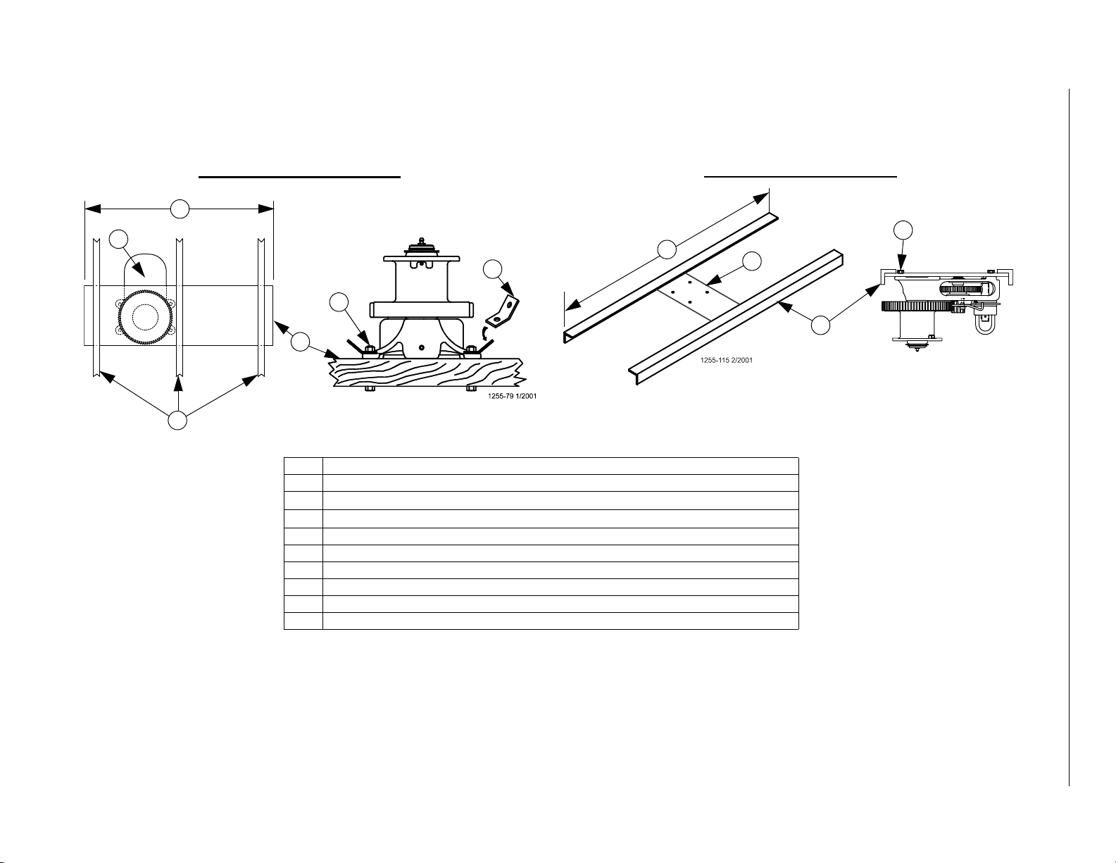
Power Lift Winch Installation
Power Lift Winch Support (Steel or Wood)
Item Description
1 Power Lift Winch Support: 2'' x 8'' [50 x 200 mm] board spanning at least 3 trusses.
2Power Lift Winch
3Truss
4 Cable Hook: Install as shown.
5 5/16-18 Bolt, Washer, and Locknut (In parts package)
6 Angle Iron: Long enough to span 2 Trusses.
7 3/8" [9.5mm] Thick Steel Mounting Plate
8 Long enough to span 2 Trusses
9 Long enough to span 3 Trusses
4
2
Wood Truss Installation Steel Truss Installation
7
5
6
5
8
1
9
3
Figure 3.Power Lift Winch Support
Installation
10 MC2507A
Attaching Winch Support to Trusses
3
4
Figure 4. Mounting the Power Lift Winch and Support to Trusses
Item Description
1 Feeder Line
2 Winch & Winch Support
3Winch Centered directly over Feeder Line
4Lag Bolts
5 Steel Truss
6 Wood Truss
11
2
Wood Truss Installation Steel Truss Installation
5
24
6
5
5

11
MC2507A
Main Winch Cable
1.Double Back Pulleys are required at the Winch. (See Figure 5.)
Figure 5.Double-Back Pulley at Winch
8
6
34
1
2
5
Item Description
1 Manual Winch
2ThrowBack
3 "X" + 2’ [61cm]
4 Distance Feeder to be raised "X"
5 All systems require double-back Pulleys
6 Use (2) Cable Clamps to secure main cable to double-back pulley
7 Main Winch Cable
8 Weight
7
7
8

Installation
12 MC2507A
Cable Routing at Winch
Wrapping Cable on Winch Drum
Ceiling Hook Installation
Item Description
1 Direction of Rotation (Clockwise)
2 Winch Drum Relief with Setscrew
3 Route 3/16" Main Winch Cable
through Winch Drum Relief
4 Tighten Set Screw to Anchor Cable
Figure 6.Winch Cable Routing
1
2
3
4
Item Description
1 Rotate Winch Drum one full rotation Clockwise
2 Guide Cable against Flange
3 Cable must not overlap. Each Wrap tight to the
next.
1
2
3
Figure 7.Wrapping Cable on Winch Drum
Item Description Part No.
1 Ceiling Hook 28550
2 Steel Truss --
3 Wood Truss
4 1/4-20 Lag Screw --
5 Cable Travel Direction --
6Weld --
Figure 8.Ceiling Hook Installation
4
22
5 5
5
5
4
63
4
2
1111

Installation
13
MC2507A
Suspension Drop Lines
Adequate overhead structure must be provided to support the weight of the Feeder, Birds, Power Units, etc. Refer to the “Component Weight Chart” on
page 66 for individual component weights.
1.Suspensions Drop Lines should always line up with Trusses. If attaching drop lines to Trusses is impossible, adequate load baring structure must be used.
2.Stagger Drop Lines as shown. When Staggered, Drops are spaced 4’ [1.2 m] or 5’ [1.5 m] apart to coincide with 8’ [2.4 m] or 10’ [3 m] Truss Spacing.
(See Figure 9.)
3.Drops are required at the ends of the last Trough at both ends, and within 12" [30.4 cm] of each Trough joint. (See Figure 9.)
4.Each 90° Elbow needs its own Suspension Drop. (See Figure 10 on page 14)
5.Extra Drop Lines need to be added to support Power Units.(See Figure 10 on page 14)
6.Extra Drop Lines required at the Intake Cup if installed in middle of loop. (See Figure 10 on page 14)
Loop Width
The ULTRAFLO®Feeder loop is 44" [1.12 m] wide (minimum). Additional width may be achieved by cutting less pipe or by adding a straight section of
tube between Elbows.
Alternate Drop Lines every 4’ [1.2m] or 5’
[1.5m] (Depends on truss spacings)
Item Description
1 Suspension Drop Line
2 44" [1.12 m] wide (minimum)
3 Center of Feeder Line
4 4’ [1.2 m] or 5’ [1.5 m]
5IntakeCup(Figure 10)
2
Figure 9.Suspension Drop Lines
5
1
A drop is required within 12" [30.4 cm]
Maximum distance from Trough joints.
1
7
1
1
4
11
1
1
1
1
1
3
3
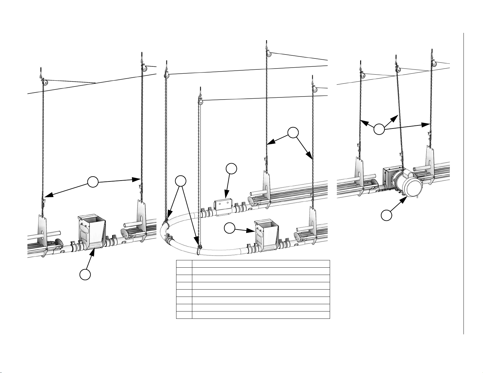
Installation
14 MC2507A
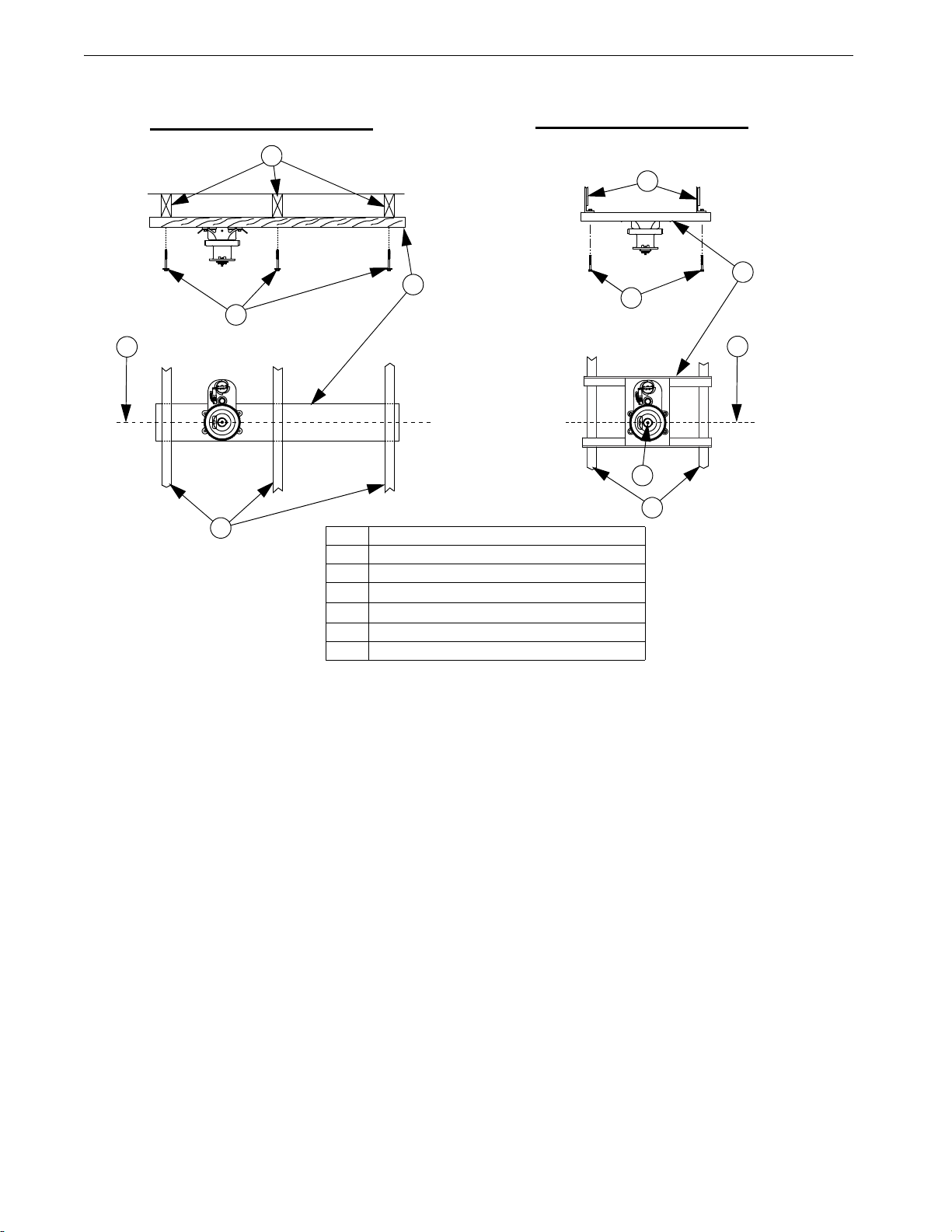
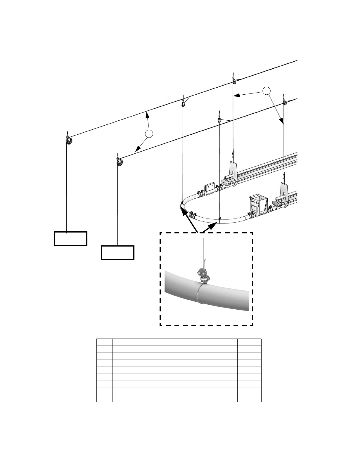
Drop Lines for Power Unit, Intake Cup, and Ends of Loop
Item Description
1 Intake Cup
2Clean-Out
3PowerUnit
4 Drop Line at center of Elbow Support
5 Drop Line at end of Trough
6 Drop Lines for Power Unit
7 Drop Lines at Intake Cup (Required if located mid loop.
Figure 10.End of Loop and Power Unit Suspension
1
4
2
56
3
1
Drops required on each
side of Intake Cup if not at
the end of feed loop.
7

Installation
15
MC2507A
Screw Hook Installation
Install Screw Hooks at locations shown in (Figure 9).
If distance raised (3) is greater than (2) then stagger Screw hooks (4) as shown.
Important! Suspension Drops must be alternated from side to side on the Feeder Loop to distribute Feeder
and Bird loads. This will space the Drops every 4’ to 5’ [1.2 to 1.5 m] depending on Truss spacing.(See
Figure 9.)
3
1
2
4
Item Description Part No.
1 3" [7.6 cm] Offset
2 Distance of Cable Travel (Recommended 8’ [2.4m] on center). Do Not exceed 10’ [3m].
3 Distance Feeder is to be raised
4 Screw Hook (Stagger as shown if (3) is greater than (2) 2041
5 Screw in Screw Hook full length of threads.
6 3/32 [2mm] Drop Cable
7 Screw Hook Opening facing opposite direction of travel.
8 Winch End (Direction of Travel).
Figure 11.Screw Hook Installation
View up to Ceiling
5
6
8
7

Installation
16 MC2507A
Suspension Drop Line Installation
1.Attach a Pulley (Item 1) to each Hook.
2.Thread the end of the 3/32” or 1/8” cable through the Pulley toward the Winch. Clamp this end to the 3/16” winch cable about 6” (150 mm) from the Pulley,
using a 3/16 inch Cable Clamp (See Figure 11.). Allow enough drop cable to reach the eye of the Hanger (Single Perch), or the Top Perch Tube (3 Perch)
and thread back through Adjustment Leveler (Item 8).
3.Begin installing suspension drops at the Winch and proceed toward the elbows.
4.Keep the main cable tight between drops. Hang a weight on the end of the main cable to maintain tension.
Figure 12.Supporting the Elbows
5
3
3
3 Perch
Single Perch
10
9
1
2
2
7
Item Description Part No.
1 Pulley 3004
2 Cable Clamp 14898
3 6" [150mm] --
5 Main Cable
6 3/32 [2mm] Drop Cable
7 Screw Hook Opening facing opposite direction of travel.
8 Adjustment Leveler 14337
9 Approximately 20" [50.8 cm] --
10 Approximately 12-1/4" [31.1 cm] --
Use the large hole for 1/8" [3 mm] Drop Cable.
Use the small hole for 3/32" [2 mm] Drop Cable.
8
Installation
17
MC2507A
Elbow Support
1.(Figure 13) shows proper suspension points for the elbows.
2.Adequate support must be provided at the elbows to prevent sagging.
Figure 13.Supporting the Elbows
Item Description Part No.
1 Pulley 3004
2 Cable Clamp 14898
3 6" [150mm] --
4 Weight --
5 Main Cable
6 3/32 [2mm] Drop Cable
7 Screw Hook Opening facing opposite direction of travel.
8 Winch End (Direction of Travel).
5
6
Weight
Weight

Installation
18 MC2507A
Loop Components Installation
The following will provide guidelines for the installation, beginning at Intake Cup location and proceeding in the
direction of auger travel.
Suspended Systems: Measure and mark the trough so that when it is installed, the joint with the next trough
will be located directly below a suspension drop line.
Intake Cup and Elbows Installation
1.Attach an Elbow (Item 2) to the Intake Cup (Item 1) using a Tube Coupling (Item 3) as shown.
2.Cut Elbows to length to achieve desired width.
Note: 44" [111.8cm] Minimum Center to Center loop width.
Important! Cut the same amount off of each Elbow and leave a minimum 2" of straight. (See Figure 14.)
3.If extra width or length is needed, add a straight piece of Pipe (Item 4). and an extra 2" Tube Coupling.
Clean-Out Installation
1.Install a Clean-out (Item 1) between the Elbow and the End Cap using Tube Couplings (Item 2) as shown.
2.Install a Clean-out Lock (Item 3) as shown.
FeedFlowDirection
FeedFlowDirection
1
2
2
Leave 2" [5.1cm] of Straight Minimum.
Cut equal amounts from each Elbow.
Item Description Part No
1 2" Tube Coupling 48722
2 ULTRAFLO Steel Elbow 9639
3 Clean-Out 13405
4* 35.92" Straight Tube (If needed) 13269
4*
Figure 14.Intake Cup & Elbows Installation
1
44" [111.8cm] Center
to Center Minimum.
Figure 15.Clean-out Installation
Item Description Part No
1 2" Tube Coupling 48722
2 Clean-Out 13405
3 Clean-Out Lock Kit 57375
3
2
1
1

Installation
19
MC2507A
Trough, Trough Hangers, and Perch Tubes Installation
Suspended and Aviary Installation
1.Cut the Bell end off of Troughs if needed to install End Cap Assemblies (Item 2). (See Figure 16.)
2.Install Trough Hangers/Supports as follows....
•Single Perch and Aviary Application- Install Trough Hanger Tops (Item 3) and Bottoms (Item 4).
•Three Perch- Install Short 3 Perch Feeder Supports (Item 7).
3.Install an End Cap Assembly (Item 2) if needed.
Important! Do Not use the Nuts included with U-Bolts (Item 8). Use 1/4-20 Lock Nuts (Item 9) instead.
4.Install Perch Tubes (Item 10) using U-Bolts (Item 8). and Conduit Plugs as shown.
5.Use Couplers (Item 11) where needed.
Figure 16.Installing Hangers
10
8
76
9
14
Item Description Part No.
1 Double Sided UF Trough 56110-X
2 End Cap Assembly 56115
3 Single Perch UF Feeder Support Bottom 56117
4 Single Perch UF Feeder Support Top 56118
5 10-24 x .375 Machine Screw 25124
6 10-24 Lock Nut 34019
7 Short 3 Perch UF Feeder Support 56476
Item Description Part No.
8 1/4-20 U Bolt 56487
9 1/4-20 Lock Nut 1269
10 Perch Tube (20’ piece) 52767
11 1.00" Aviary Conduit Coupler 52900-1
12 10-24 x .500 Machine Screw 1795
13 10-24 Kepnut 27725
14 1" Conduit Plug 56264
1
Bell 4
Feed Flow
12
13
10
5
11
14
2
6
56
5
3 Perch
311
6" [152.4mm]
Maximum
6" [152.4mm]
Maximum
6" [152.4mm]
Maximum
Single Perch
2
2
6" [152.4mm]
Maximum
5
6
Installation
20 MC2507A
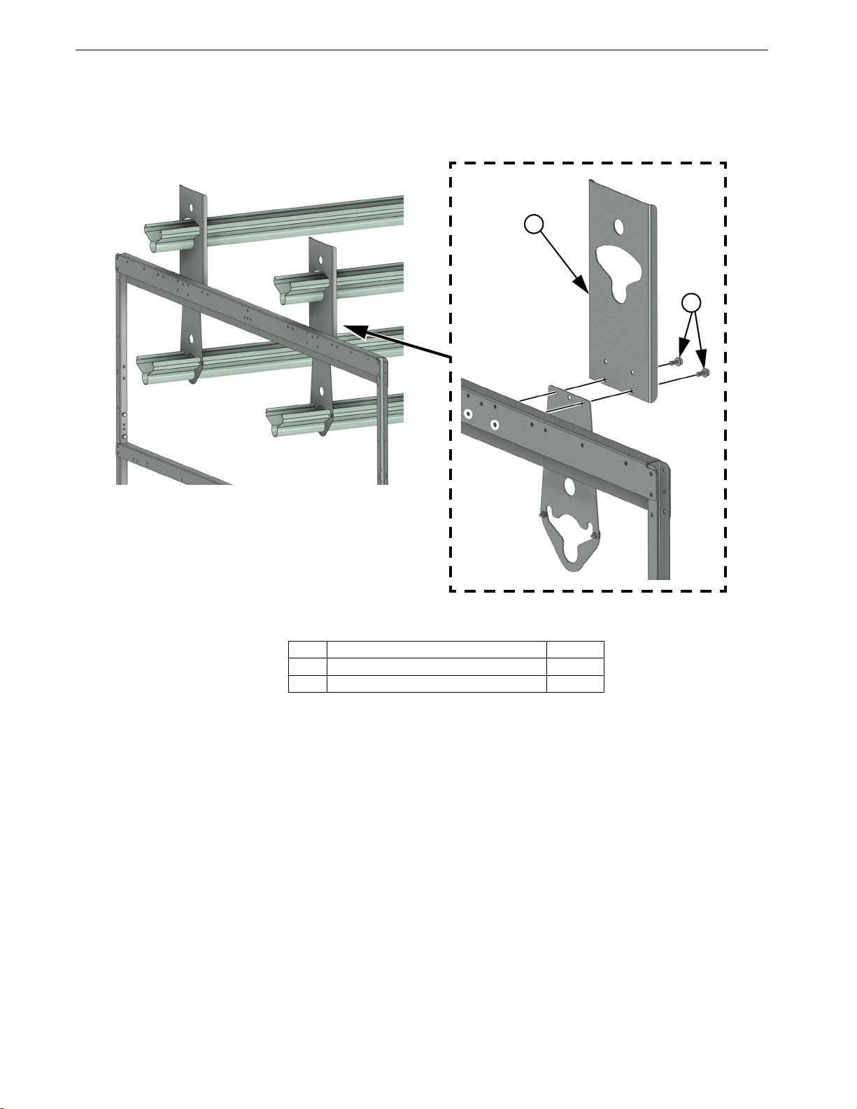
Aviary Upper Level Installation
A Feed Loop can be installed on the upper level if needed. The Components install the same way as the
other tiers with the exception of the Hangers.
1.Install Upper Level Feeder Supports (Item 1) using M8 Taptites (Item 2) as shown.
Item Description Part No.
1 Upper Level Feeder Support 56306
2 M8 x 16 Taptite 201047
Figure 17.Aviary Upper Level Installation
2
1
Table of contents
Other Chore-Time Industrial Equipment manuals


