AUMA GP 10.1 User manual
Multi-turn gearboxes
GP 10.1 –GP 30.1
Assembly and commissioningOperation instructions

Read operation instructions first.
●Observe safety instructions.
●These operation instructions are part of the product.
●Store operation instructions during product life.
●Pass on instructions to any subsequent user or owner of the product.
Target group:
This document contains information for assembly, commissioning and maintenance staff.
Table of contents Page
31. Safety instructions................................................................................................................. 31.1. Basic information on safety 41.2. Range of application 41.3. Warnings and notes 41.4. References and symbols
52. Identification........................................................................................................................... 52.1. Name plate 62.2. Short description
73. Transport, storage and packaging........................................................................................ 73.1. Transport 83.2. Storage 83.3. Packaging
94. Assembly................................................................................................................................ 94.1. Mounting position 94.2. Handwheel fitting 94.3. Multi-turn actuators for motor operation 104.3.1. Input mounting flange: mount 114.4. Mount gearbox to valve 114.4.1. Output drive types B 114.4.1.1. Gearbox with output drive types B: mount to valve
135. Commissioning...................................................................................................................... 135.1. Seating via multi-turn actuator
146. Servicing and maintenance................................................................................................... 146.1. Preventive measures for servicing and safe operation 146.2. Maintenance intervals 146.3. Disposal and recycling
167. Technical data......................................................................................................................... 167.1. Technical data Multi-turn gearboxes
198. Spare parts............................................................................................................................. 198.1. Multi-turn gearboxes GP 10.1 –GP 14.1 (2.4:1/3:1/4:1) 218.2. Multi-turn gearboxes GP 14.1 (4:1/8:1) 238.3. Multi-turn gearboxes GP 16.1 (4:1/8:1) 258.4. Multi-turn gearboxes GP 25.1 –30.1(16:1) 278.5. Multi-turn gearboxes GP 25.1 30.1 (4:1/8:1)
31Index........................................................................................................................................
2
GP 10.1 –GP 30.1
Table of contents

1. Safety instructions
1.1. Basic information on safety
Standards/directives Our products are designed and manufactured in compliance with recognised
standards and directives.
The end user or the contractor must ensure that all legal requirements, directives,
guidelines, national regulations and recommendations with respect to assembly,
electrical connection, commissioning and operation are met at the place of installation.
Safetyinstructions/warn-
ings All personnel working with this device must be familiar with the safety and warning
instructions in this manual and observe the instructions given. Safety instructions
and warning signs on the device must be observed to avoid personal injury or property
damage.
Qualification of staff Assembly, electrical connection, commissioning, operation, and maintenance must
be carried out exclusively by suitably qualified personnel having been authorised by
the end user or contractor of the plant only.
Prior to working on this product, the staff must have thoroughly read and understood
these instructions and, furthermore, know and observe officially recognised rules
regarding occupational health and safety.
Work performed in potentially explosive atmospheres is subject to special regulations
which have to be observed.The end user or contractor of the plant are responsible
for respect and control of these regulations, standards, and laws.
Electrostatic charging Das Getriebe muss am Installationsort geerdet werden.
Highly efficient charge generating processes (processes more efficient than manual
friction) on the device surface must be excluded at any time, since they will lead to
propagating brush discharges and therefore to ignition of a potentially explosive
atmosphere.
This also applies to fireproof coatings or covers available as an option.
Ignition hazards Gearboxes were subjected to an ignition hazard assessment in compliance with the
currently applicable standard according to ISO 80079-36/ -37.Hot surfaces,
mechanically generated sparks as well as static electricity and stray electric currents
were identified and assessed as major potential ignition sources.Protective measures
to prevent the likelihood that ignition sources arise were applied to the gearboxes.
This includes in particular lubrication of the gearbox, the IP protection codes and the
warnings and notes contained in these operation instructions.
Commissioning Prior to commissioning, it is important to check that all settings meet the requirements
of the application. Incorrect settings might present a danger to the application, e.g.
cause damage to the valve or the installation.The manufacturer will not be held
liable for any consequential damage. Such risk lies entirely with the user.
Operation Prerequisites for safe and smooth operation:
●Correct transport, proper storage, mounting and installation, as well as careful
commissioning.
●Only operate the device if it is in perfect condition while observing these instruc-
tions.
●Immediately report any faults and damage and allow for corrective measures.
●Observe recognised rules for occupational health and safety.
●Observe the national regulations.
●During operation,the device warms upand increasedsurfacetemperaturemay
occur.To prevent possible burns, we recommend checking the surface temper-
ature using an appropriate thermometer and wearing protective gloves, if re-
quired, prior to working on the device.
Protective measures The end user or the contractor are responsible for implementing required protective
measures on site, such as enclosures, barriers, or personal protective equipment
for the staff.
3
GP 10.1 –GP 30.1 Safety instructions
Maintenance To ensure safe device operation, the maintenance instructions included in this manual
must be observed.
Any device modification requires prior written consent of the manufacturer.
1.2. Range of application
AUMA multi-turn gearboxes are designed for the operation of industrial valves, e.g.
gate valves and globe valves.
Other applications require explicit (written) confirmation by the manufacturer.
The following applications are not permitted, e.g.:
●Industrial trucks according to EN ISO 3691
●Lifting appliances according to EN 14502
●Passenger lifts according to DIN 15306 and 15309
●Service lifts according to EN 81-1/A1
●Escalators
●Continuous duty
●Radiation exposed areas in nuclear power plants
No liability can be assumed for inappropriate or unintended use.
Observance of these operation instructions is considered as part of the device's
designated use.
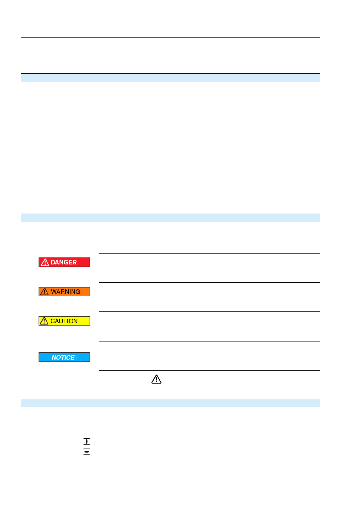
1.3. Warnings and notes
The following warnings draw special attention to safety-relevant procedures in these
operation instructions, each marked by the appropriate signal word (DANGER,
WARNING, CAUTION, NOTICE).
Indicates an imminently hazardous situation with a high level of risk. Failure
to observe this warning results in death or serious injury.
Indicates a potentially hazardous situation with a medium level of risk.Failure
to observe this warning could result in death or serious injury.
Indicates a potentially hazardous situation with a low level of risk. Failure to
observe this warning could result in minor or moderate injury. May also be
used with property damage.
Potentially hazardous situation. Failure to observe this warning could result
in property damage. Is not used for personal injury.
Safety alert symbol warns of a potential personal injury hazard.
The signal word (here: DANGER) indicates the level of hazard.
1.4. References and symbols
The following references and symbols are used in these instructions:
Information The term Information preceding the text indicates important notes and information.
Symbol for CLOSED (valve closed)
Symbol for OPEN (valve open)
➥Result of a process step
Describes the result of a preceding process step.
4
GP 10.1 –GP 30.1
Safety instructions
2. Identification
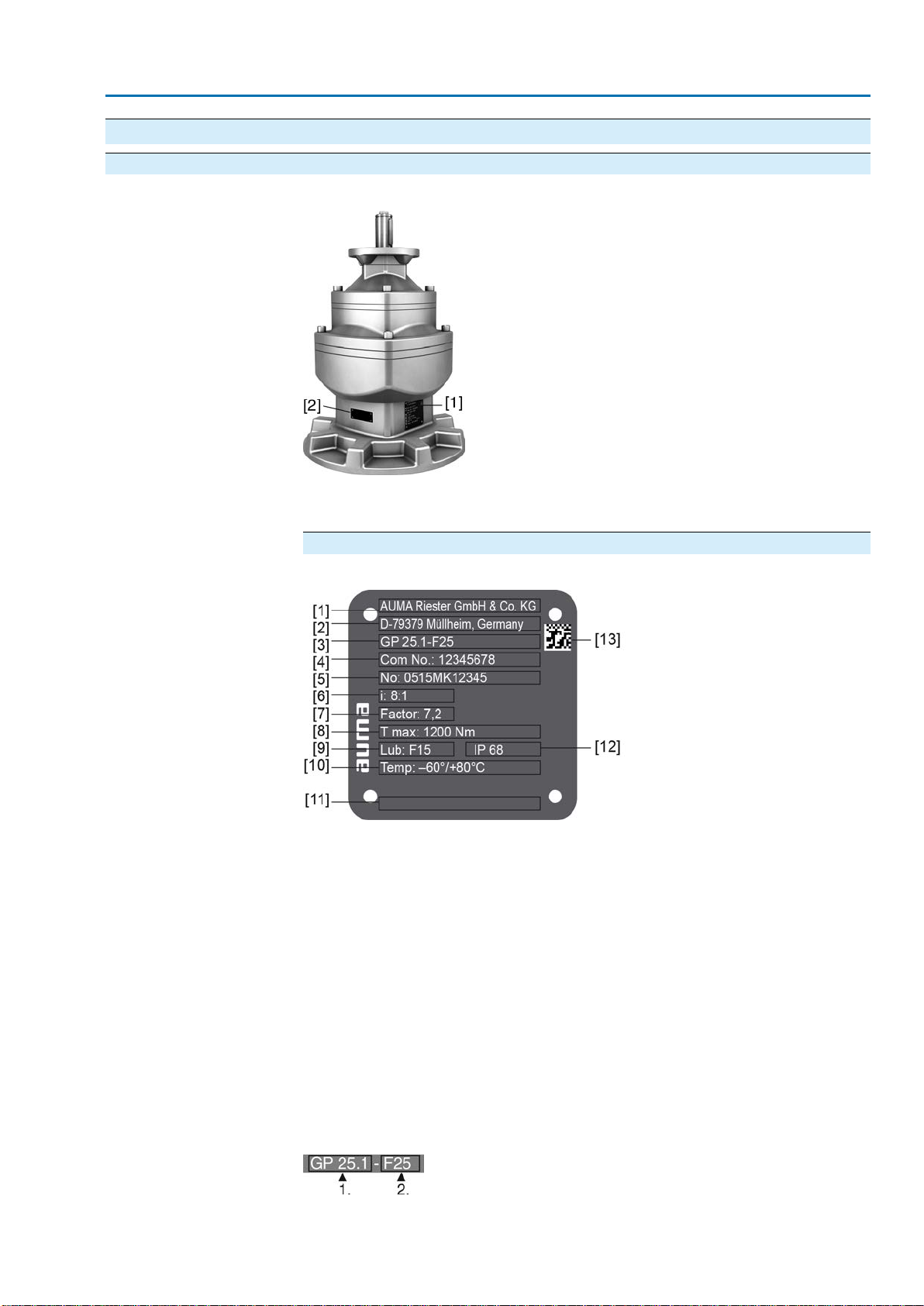
2.1. Name plate
Figure 1: Arrangement of name plates
[1] Gearbox name plate
[2] Additional plate, e.g. KKS plate (Power Plant Classification System)
Description of gearbox name plate
Figure 2: Gearbox name plate (example GP 25.1)
[1] Name of manufacturer
[2] Address of manufacturer
[3] Type designation - valve attachment (flange)
[4] Order number
[5] Serial number
[6] Reduction ratio
[7] Factor
[8] Max. valve torque (output torque)
[9] Type of lubricant
[10] Permissible ambient temperature
[11] Can be assigned as an option upon customer request
[12] Enclosure protection
[13] Data Matrix code
Type designation Figure 3:Type designation (example)
1. Type and size of gearbox
5
GP 10.1 –GP 30.1 Identification
This manual suits for next models
4
Table of contents
Other AUMA Industrial Equipment manuals


