2
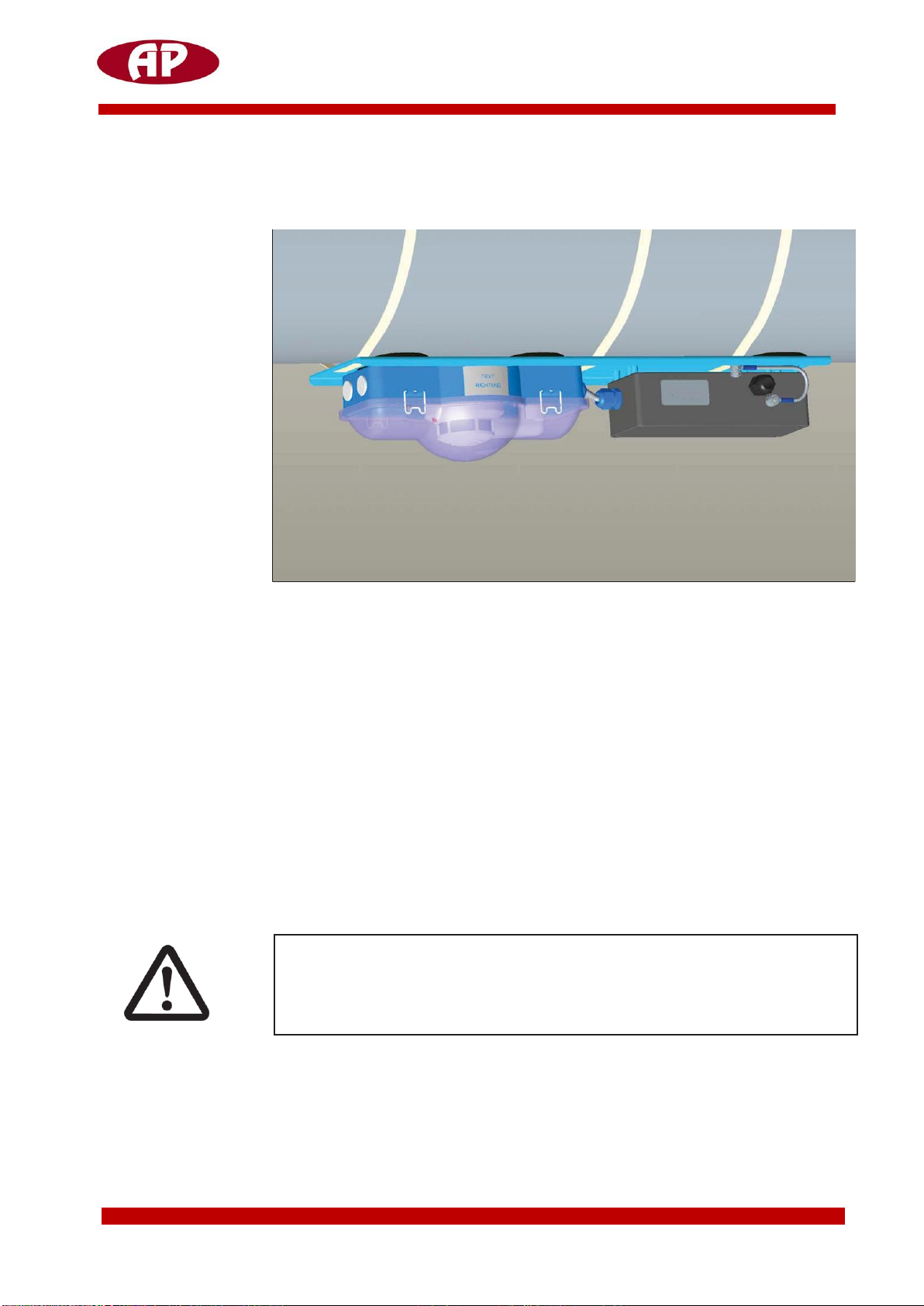
ATEX –Duct Smoke Detector
Content
Content
..................................................................................................................................................................2
1
Introduction
........................................................................................................................................................4
2
Aboutthisdocument
.......................................................................................................................................5
2.1
Objectives and intended readers
.............................................................................................................5
2.2
Symbols used
................................................................................................................................................5
3
Safety
....................................................................................................................................................................6
3.1
Guarantee claims
.........................................................................................................................................7
4
Project planning
...............................................................................................................................................8
5
Technical data
.....................................................................................................................................................9
6
General information
.....................................................................................................................................11
6.1
Operation of the LRS 04 Ex
.....................................................................................................................11
6.2
Transport,storageandunpacking
..........................................................................................................11
6.3
Scope of delivery
.......................................................................................................................................11
7
Rules and regulations
...................................................................................................................................12
7.2
Safety in potentially explosive atmospheres
...........................................................................................13
7.3
Intended use
...............................................................................................................................................13
7.4
General safety information and
protective measures
.......................................................................14
7.4.1
Explosion-protection regulations
..............................................................................................14
7.4.2
Classification of hazardous areas
..............................................................................................17
8
Product description
........................................................................................................................................18
8.1
Design and mode of operation
of LRS 04 Ex
.........................................................................................18
8.1.1
Terminal assignment in the connection box of the
LRS04Ex
..........................................20
8.2
Device functions and display elements of
the LRS 04 Ex
...................................................................20
8.3
Accessories for the LRS 04 Ex
...................................................................................................................21
8.3.1
Power supply and tripping unit NAG 03
.................................................................................21
8.3.2
Signal and display control element SAB 04
...........................................................................24
8.3.3
Manual actuation pushbutton 422 Ex
.....................................................................................24
8.3.4
Connection box Ex
..........................................................................................................................25