Trox RM-O-VS User manual

Smoke Detector
Type RM-O-VS
Approved by the German Institut für Bautechnik
4/6.1/EN/3

Contents · Technical Data
Contents · Technical Data 2
Description · Application 3
Installation Instructions 4
Circuit Diagram · Wiring Diagrams 5
Overview of Functions 6
Inspection and Maintenance 7
Order Details 8
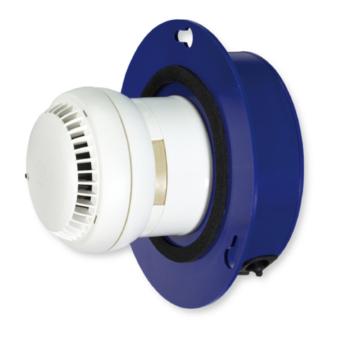
Smoke detector with power supply, monitoring electronics,
smoke alarm and air velocity monitor
Connection (plug socket) for diagnostic instrument
Push button “Test/Reset”
Green LED “System Monitoring”
Red LED “Alarm”
Yellow LED “Pollution Monitoring”
Blue LED “Air Velocity Monitoring”
Remote control terminal
Diagnostic instrument
Note:
Smoke detectors type RM-O-VS require maintenance
only once per year due to the increased safety
monitoring function.
Technical Data
– Supply voltage: 230 V, 50/60 Hz
– Power consumption: max 25 VA
– Enclosure rating: IP 42
– Permitted ambient temperature: + 10 °C to + 60 °C
– Permitted air velocity in ventilation duct:
1 m/s to 20 m/s
– Permitted relative humidity: 0 – 90% relative humidity
(condensation and water vapour can cause false alarms)
– Warning limit for air flow: 2 m/s
– Warning limit for high pollution: > 70 ± 10 units
– System monitoring: electric fault
– EMC: interference suppression to EN 60801-2 and
60801-4
– Weight: 1,5 kg
Scope of Supply
Visual smoke alarm, power supply, switched relay, signal
lights (LED), pushbutton, remote control and diagnostic
instrument connection, electronic monitor, integrated in
a plastic housing, wired ready for connection to snap
terminals, drilling template and fixing materials.
Available accessories:
– Diagnostic instrument type D-RM-O-VS to scan pollution
level, measurement range 0 to 100 units; hand held unit
with 1m long connecting lead and plug, battery supply
9 V.
– Remote control terminal type T-RM-O-VS surface
mounting or type T-RM-O-VS/1 panel mounting (size
48 x 96 x 63) with LED’s for alarm, air flow, pollution and
system monitoring; plug socket connection for diagnostic
instrument type D-RM-O-VS and pushbutton for test/reset
function.
2
Smoke Detector
Type RM-0-VS
Terminal
Type T-RM-0-VS
Terminal
Type T-RM-0-VS/1
Diagnostic
Instrument
Type D-RM-0-VS

Description · Application
3
Description
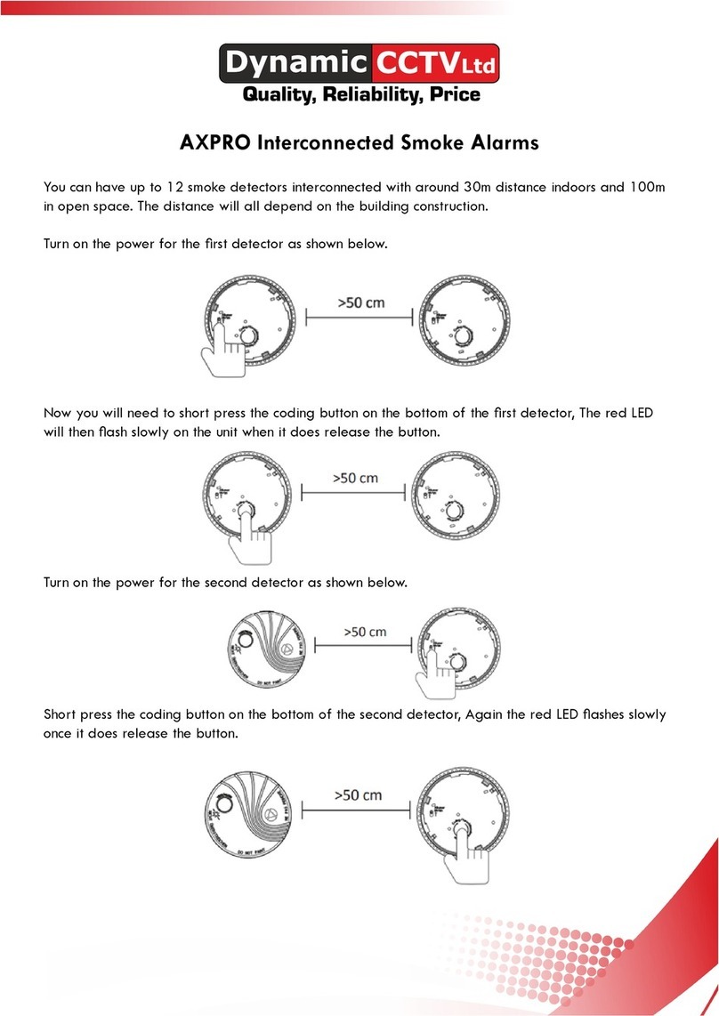
The smoke detector works on the optical light scattering
principle and is used to monitor the ventilation duct in air
conditioning systems. When used with a fire damper, it
prevents cold smoke with a temperature of 72 °C from
propagating through the AC system.
In the function mode, the smoke alarm of the smoke
detector is permanently flushed by the air flow in the duct
being monitored. If the smoke density exceeds a specific
concentration, the smoke alarm breaks the power circuit
to the control device of the fire damper; and the damper
closes. To ensure the specified function, the smoke detector
is also fitted with an air velocity sensor which monitors the
air flow in the immediate vicinity of the smoke alarm. A lack
of air flow, eg. caused by a closed damper or fan failure, is
signalled by an LED and opening relay contact.
The electrical safety circuits of the smoke detector are
constantly checked electronically and signalled on failure
by an LED and closing relay contact. At the same time, the
opening of the alarm relay contact interrupts the control
circuit and the fire damper closes. To avoid false alarms
due to pollution, the smoke alarm sampling chamber is
continuously monitored electronically. If a permitted threshold
of “> 70 ± 10 units” is exceeded, a signal is given by an LED
and closing relay contact.
The actual pollution value can be scanned directly at the
smoke detector or on the remote control terminal using the
diagnostic instrument.
Installation of a remote control terminal enables the electrical
function tests to be carried out from a central point, e.g. fire
control room.
Application
All fire dampers fitted with electric or electric/pneumatic
control devices which operate when voltage is removed may
be controlled via the smoke detector.
This is recorded in the general building authority permits for
Trox fire damper.
The smoke detectors are marked with the U symbol in
accordance with the Approval Mark regulations in Germany.
The external verification prescribed by law is carried out by
VdS e.V, Cologne.
Smoke detector with
power supply, monitoring
electronics, smoke alarm
and air velocity monitor
Remote control terminal
Diagnostic instrument
Fire damper
Spring return actuator
Central control point
Test
Rückstellung /
Reset
Rauchauslöseeinrichtung
Typ RM-O-VS
>70% v<2m/sec
Elektronik
Rauch /
Smoke
Schmutz /
Pollution
Luft /
Air
Betrieb / Operation
Gebrüder TroxGmbH
D-47504 Neukirchen-Vluyn
Telefon0 28 45/2 02-0
Telefax0 28 45/20 22 65
Alarm / Störung / Failure
Anschluß
Diagnosegerät
Diagnostic link
Betrieb / Operation
Alarm / Störung / Failure
Rauch /
Smoke
Elektronik
Test/ Rück-
stellung
Reset
Anschluß
Diagnosegerät
Diagnostic link
Schmutz /
Pollution
Luft /
Air
>70% v < 2m/sec
TerminalT-RM-O-VS zur
Rauchauslöseeinrichtung
RM-O-VS
15
Typ D-RM-0-VS
1
8
9
10
11
12
Airflow
v = 1-20 m/s

Installation Instructions
Smoke detector with power supply, monitoring
electronics, smoke alarm and air velocity monitor.
1.1
Housing cover
Air duct provided by others
Drilling template
Fixing screw
Inspection opening by others
Electrical connections
Installation Instructions
– The smoke detector must be installed on a vibration-free
surface, in an area of the duct to be monitored having a
uniform air flow over the smoke alarm during normal
operation.
– Attach the drilling template to the centre of the air duct
(H/2) and drill holes.
– Remove housing cover.
– Attach housing to air duct.
– For visual inspection or to replace the smoke alarm, an
inspection opening should be provided on the upper or
lower side of the air duct.
Optional electrical connections (mains connection and
connection to control device of fire damper) should be
such that the entire smoke detector can be removed to
replace the smoke alarm.
The smoke alarm can be released from its lock by turning
anti-clockwise. When re-inserted it is locked by turning
clockwise.
– Connect control device of fire damper to the smoke
detector (terminal strip L3).
– Connect to mains.
– Connect remote control terminal (if required);
connection lines: twin core telephone cable.
– Fit housing cover.
4
145
205
80
115
185
30
88
1.1
H/2
H
Rauchauslöseeinrichtung
TypRM-O-VS
Luftrichtung
Ø 90
Air intake opening
(Distance from internal side
of the ventilation duct)
Air flow direction

Circuit Diagram · Wiring Diagrams
5
Fig 1
Fig 2
Fig 3
Fig 4
N (–)
L (+)
24 V
230 V
50/60Hz
F1
b3
L4L3L9L7
b1
L10
b4b2
B2
PE
123456789
10
456
123
123
123
123
123
L1
LLN
PE
N
L1
LLN
PE
N
L1
LLN
PE
N
L1
LLN
PE
N
123456789
10
L4
L4
L4
L3
L3
L3
B1
+–
A
AA
AA
The entire electrical installation must be in accordance with VDE
and the local EVU regulations.
Fig 1 Connection diagram for smoke detector
(fire damper closed)
Fig 2 Installation without separate power supply to DC
control device
A
on the fire damper to be controlled,
maximum load: 8 W / 24 V-
Fig 3 Installation with separate power supply for
control device
A
on the fire damper to be controlled,
maximum switched power 250 V / 10 A
or 24 V- / 200 W
Fig 4 Special installation (voltage on to operate principle)
without separate power supply to AC control device
A
on the fire damper to be controlled,
maximum switched power 250 V / 10 A
L
1
Mains connection 230V 50/60 Hz
L
3
Control device connection (volt-free)
Switched power 250 V / 10 A or 24 V- / 200 W
L
4
Connection of external control max 8 W / 24 V-
Connection for 24 V- external supply:
Residual wave max 2 %;
Consumption min 520 mA;
Without 8 W consumption 190 mA
L
9
– L9/1-2 air velocity monitoring (volt-free)*,
– L9/3-4 pollution monitoring (volt-free)*,
– L9/5-6 system monitoring (volt-free)*
* Switched power 110 V/4 A, 24 V-/100 W
L
7
/L
10
Connection for remote control type T-RM-O-VS or
T-RM-O-VS/1; for remote control, remove link L7/1-2
b
1
b
2
Pushbutton test/reset
b
3
b
4
Connection (plug socket) for diagnostic instrument
type D-RM-O-VS
F
1
Fuse 500 mAT
B
1
Link (by others) for connecting
230 V, 50/60 Hz detector
B
2
Link (by others) for connecting
24 V- control device max 8 Watts
A
Control device for fire damper
(AC or DC)
For parallel control
Smoke detector type
type RM-0-VS
Remote control
Type: T-RM-0-VS
Type: T-RM-0-VS/1
Velocity
monitor
Smoke alarm

Overview of Functions
6
Fire damper
Open Closed
Operating Mode / Event
Mains connected
– Function status –
Mains not connected
Mains connected,
faulty electronics or
link L7/1-2 or
remote control or
smoke alarm not fitted
Pollution Level 1)
70 units
100 units
Test / Reset
– Inspection –
Smoke / Pollution 1)
100 units 3)
– Alarm status –
LED
Contact
LED
Contact
LED
Contact
LED
Contact
LED
Contact
LED
Contact
Signal
Red LED
Alarm
Blue LED
Velocity
Monitoring
Green LED
System
Monitoring
Terminal Strip
– L9–
6 5
Terminal Strip
– L9–
4 3
Terminal Strip
– L9–
2 1
Terminal Strip
– L3–
2
3
1
Yellow LED
Pollution
Monitoring
With air flow: LED on
Without air flow: LED off
relay contact:
relay contact:
2)
2)
1) Pollution corresponding to diagnostic instrument display:
Up to 70 units – Normal range –
70 units – Warning level –
100 units – Alarm status –
2) May indicate a transitional state, e.g. caused by a cloud
of dust
3) An alarm triggered by smoke (event or maintenance) can
only be cancelled by pressing the button after the smoke
alarm head has cleared of smoke.
: LED on : LED flashing : LED off

Inspection and Maintenance
7
Function Test
Smoke detectors must be inspected every 3 months after
commissioning of the air conditioning system and
maintenance carried out at yearly intervals. Inspection
and maintenance can be carried out at the same time.
Inspection
Pressing the “Test/Reset” button on the smoke detector
or on the remote control terminal interrupts the circuit to
the control device on the fire damper which then closes.
On releasing the button, fire dampers with actuators
automatically return to the open position. Fire dampers
with solenoid or magnet release must be opened locally
by hand.
The fouling of the smoke alarm can be scanned directly on
the smoke detector using the diagnostic instrument and/or
via the remote control terminal.
For signal indication, see overview of functions, page 6.
Maintenance
Check the following:
– Application and installation position
(during commissioning and after system changes)
– Correct electrical connections and no loose wires in
terminals
– Electrical interaction of signal emitter, display and control
devices on fire damper
– Response of smoke alarm to smoke aerosol, e.g. cigarette
smoke or smoke from smoke cartridge. When the
permitted concentration limit is exceeded, the smoke
alarm interrupts the circuit to the control device on the
fire damper to be controlled and the damper closes
– Check response of air velocity monitor, e.g. switch off fan
For signal indication see overview of function, page 6.
Eliminating Faults
If inspection or maintenance has revealed any faults, these
must be repaired immediately. Faulty components must be
replaced only by original Trox spare parts.
Only the manufacturer may make repairs to the smoke
detector.
If a function test reveals that the smoke detector is working
correctly but the fire damper to be controlled is not closing,
the control device on the damper and the damper itself
must be checked for operation.
Smoke detector with power supply, monitoring electronics,
smoke alarm and air velocity monitor
Connection (plug socket) for diagnostic instrument
Pushbutton “Test/Reset”
Green LED “System Monitoring”
Red LED “Alarm”
Yellow LED “Pollution Monitoring”
Blue LED “Air Velocity Monitoring”
Air duct supplied by others
Test tube for checking
response/function
(by others)
13
1
2 3 45 6 7
Approx. 80-90
20
Approx. 90-100

Design changes reserved · All rights reserved © Gebrüder Trox GmbH (10/2000)
Order Code
Order Details
8
Description
Smoke detector (smoke detection using optical light scattering
principle) with general building supervision approval from the
Institut für Bautechnik Berlin, for fire dampers with electric
or electric/ pneumatic control device (voltage off to operate),
suitable for protection against smoke transmission in air
conditioning systems, even with cold smoke t 72 °C;
suitable for air velocities of 1 m/s to 20 m/s.
With additional functions for monitoring the air flow in the
measurement area of the smoke alarm, the pollution level
on the smoke alarm sampling chamber and the system
electronics (maintenance once/year).
Scope of supply: see page 2.
Order Example
Make: TROX
Type: RM-O-VS
Quantity: 5
RM-O-VS
Order Code
Description:
Diagnostic instrument for smoke detector RM-O-VS to scan
pollution level.
Measurement range 0 – 100 units; hand unit with 1m long
connection lead and plug; battery supply 9 V.
Order example
Make: TROX
Type: D-RM-O-VS
Quantity: 1
D-RM-O-VS
Order Code
Description:
Remote control terminal for smoke detector RM-O-VS for
surface mounting or panel mounting (size 48 x 96 x 63) with
signal LEDs for alarm, air flow, pollution and system
monitoring; socket connection for diagnostic instrument
D-RM-O-VS and pushbutton for test/reset function.
Order Example
Make: TROX
Type: T-RM-O-VS or T-RM-O-VS/1
Quantity: 5
T-RM-O-VS or T-RM-O-VS/1
Table of contents
Other Trox Smoke Alarm manuals
Popular Smoke Alarm manuals by other brands

Landmann
Landmann Great Outdoors Smoky Mountain 3425GLA Assembly and owner's manual
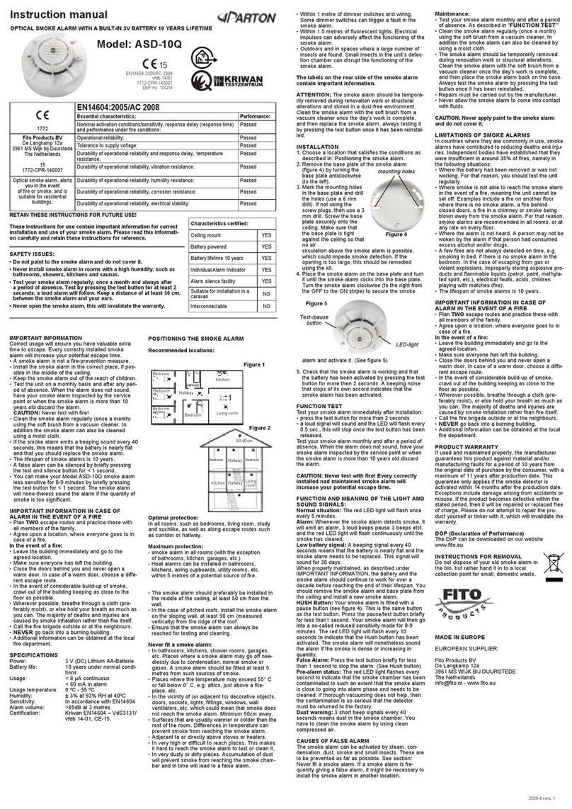
Aparton
Aparton ASD-10Q instruction manual

First Alert
First Alert PC910 user manual
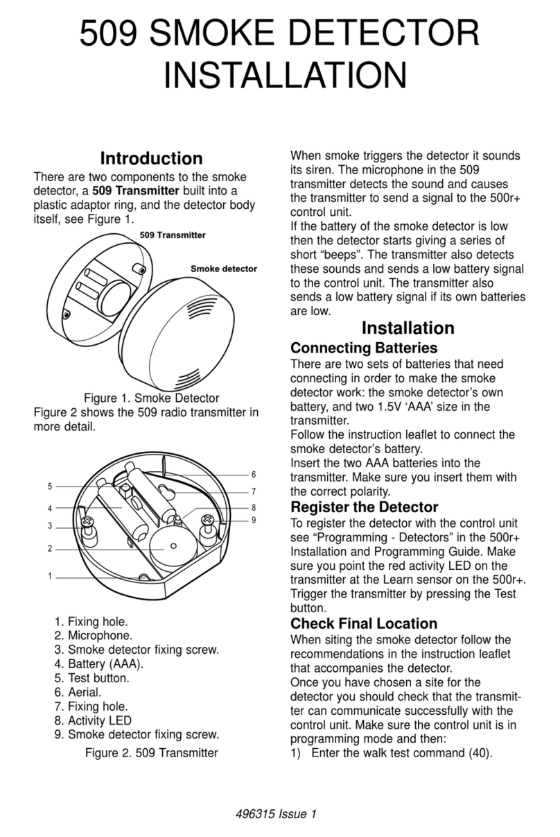
Cooper
Cooper Scantronic 509 installation manual
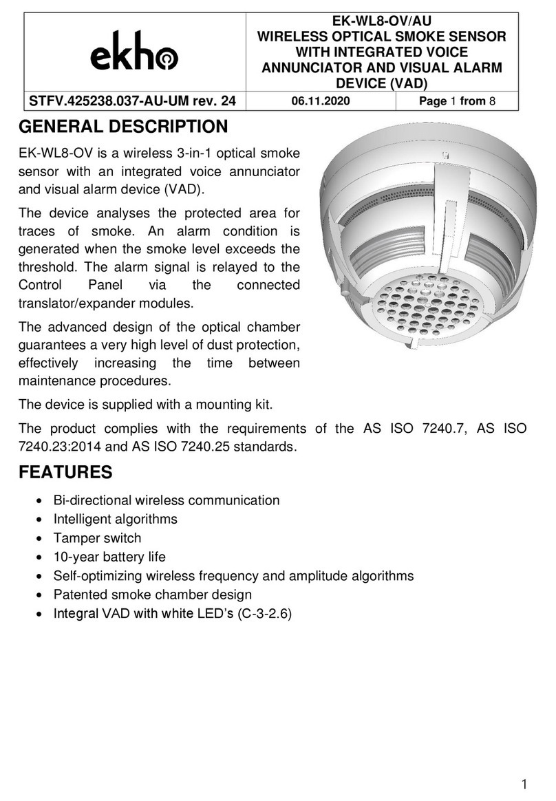
EKHO
EKHO EK-WL8-OV General description
Universal Security Instruments
Universal Security Instruments MDS300 instructions
