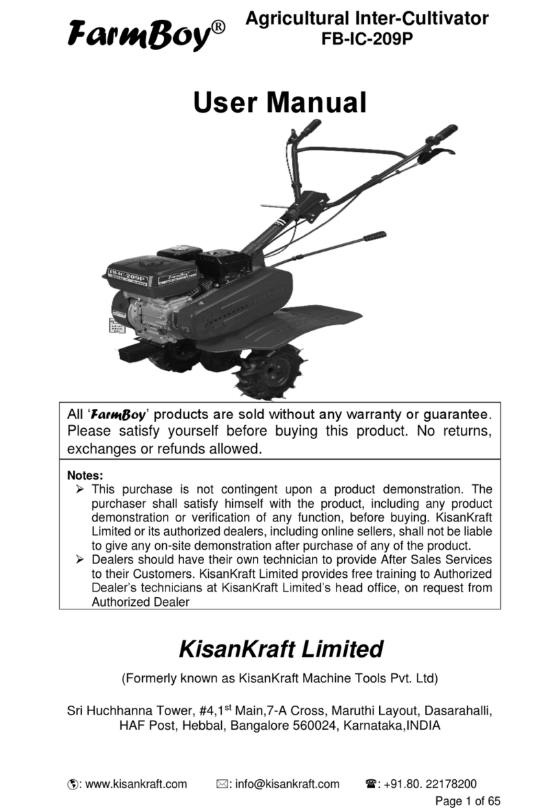
Apache Euro User manual

MOTOZAPPA
GARTEN-PFLEGEHACKE
GARDEN CULTIVATOR
MOTOBINEUSE
TUIN-HAKFREES
MOTOAZADA
MOTOENXADA
Istruzioni d'uso
Bedienungsanleitung
Operating Instructions
Mode d'emploi
Gebruiksaanwijzing
Manual de instrucciones
Instruções de uso

12
3

Leggere il libretto uso e manutenzione prima di usare la
macchina.
Lesen Sie die Gebrauchsanweisung vor der
Inbetriebnahme.
Read the instructions manual before operating on the
machine.
Lire le mode d'emploi avant l'usage.
Lees de handleiding voor het gebruik.
Antes de proceder a montar la máquina lea
atentamente estas instrucciones.
Ler o manual de uso e manutenção antes de usar a
màquina.
Attenzione: rotazione fresa
Achtung: frasenrotation
Danger: tiller rotation
Attention: danger rotation fraise
Let op: rotatie frees
¡Atencion!: la fresa gira
Atenção: fresa em rotação
Etichetta acceleratore
Gasaufkleber
Label accelerator
Plaquette acceleration
Etiket gaspedaal
Etiqueta acelerador
Etiqueta do acelerador
Innesto attrezzo
Mähbalkenantrieb
Cutter bar clutching
Embrayage barre
Maaibalkaandrijving
Manillar desembrague
transmisiòn
Engate de alfaia


Indice
Introduzione
Condizioni di utilizzazione
Suggerimenti di sicurezza
Istruzioni d' uso
Trasporto
Montaggio
Regolazione
Manutenzione
Dati tecnici
Rumore aereo
Accessori
Pericolo grave per
l'incolumità dell'operatore e
delle persone esposte.
INTRODUZIONE
Gentile cliente, lei ha acquistato una nuova attrezzatura. La ringraziamo per la fiducia accordata ai
ns. prodotti e le auguriamo un piacevole utilizzo della sua macchina.
Abbiamo creato queste istruzioni per I’uso allo scopo di assicurare, fin dall’inizio, un funzionamento privo d’incon-
venienti. Seguite attentamente questi consigli, avrete la soddisfazione di possedere per molto tempo una mac-
china che funziona a dovere.
Le nostre macchine, prima di essere fabbricate in serie, vengono collaudate in maniera molto rigorosa e, durante
la fabbricazione vera e propria, sono sottoposte a severi controlli. Ciò costituisce, per noi e per voi, la migliore ga-
ranzia che si tratti di un prodotto di riprovata qualità.
Questa macchina é stata sottoposta a rigorosi test neutrali, nel paese d’origine, e risponde alle
norme di sicurezza in vigore.
Per garantire questo, é necessario utilizzare esclusivamente ricambi originali.
L’utilizzatore perde ogni diritto di garanzia qualora vengono utilizzati ricambi non originali.
Con riserva di variazioni tecnico-costruttive.
Per informazioni e per ordinazioni di pezzi di ricambio si prega citare il numero di articolo e il numero di produzio-
ne.
Dati per l’identificazione
L'etichetta con i dati della macchina e il numero di matricola è incollata sulla parte posteriore del coperchio stegola.
Nota - Nelle eventuali richieste di Assistenza Tecnica o nelle ordinazioni delle Parti di Ricambio, citare sempre il
numero di matricola della motozappa interessata.
Condizioni di utilizzazione - Limiti d'uso
La motozappa è progettata e costruita per eseguire operazioni di zappatura del terreno. La motozappa deve la-
vorare esclusivamente con attrezzi e con ricambi originali.
Ogni utilizzo diverso da quello sopra descritto è illegale; comporta, oltre al decadimento della garanzia, anche un
grave pericolo per l'operatore e per le persone esposte.
Norme di sicurezza
Attenzione: prima del montaggio e la messa in funzione leggere attentamente il libretto istruzione.
Le persone che non conoscono le norme di utilizzazione non possono usare la macchina.
1. Impedire l’uso ai minori di anni 16.
2. Non lavorare mai con persone, soprattutto bambini od animali, nelle vicinanze. Siete responsabili
ITALIANO
11
11
1

ITALIANO
2
dei danni causati a terzi.
3. Non utilizzare la macchina nei terreni pietrosi. Lavorare solamente alla luce del giorno od in presenza di una buona illuminazione artificiale.
4. All’avviamento o durante il lavoro non mettere le mani od i piedi vicino o sotto le parti in rotazione. Non mettere in moto la macchina quando si é
davanti alle frese. Tirando la funicella di avviamento del motore le frese non devono girare (se le le frese girano intervenire sul registro di regolazione
del tendicinghia).
5. Le frese in moto sono un pericolo per i piedi, durante il lavoro indossare sempre calzature resistenti e pantaloni lunghi. Non utilizzare la macchina
quando si è a piedi scalzi o si indossano dei sandali.
6. Per trasportare la macchina fermare il motore.
7. Tutte le operazioni di servizio devono essere effettuate con motore e frese non in movimento.
8. Non abbandonare la macchina con motore in moto.
9. Il conduttore deve operare rimanendo dietro la macchina. Camminare, non correre mai con la macchina.
10. In caso di urto contro un ostacolo che blocchi la macchina, farla controllare da una stazione di servizio.
11. E' vietato avviare la macchina in locali chiusi .
12. AVVERTENZA: la benzina è altamente infiammabile, conservare il carburante in appositi recipienti, fare il rifornimento (o lo svuotamento del
serbatoio) solamente all’aperto e non fumare durante l’operazione, rimettere sempre a posto correttamente i tappi del serbatoio e del contenitore
della benzina.
13. In caso di fuoriuscita della benzina, non tentare di avviare il motore ma allontanare la macchina dall’area dove è avvenuta la fuoriuscita evitando
di creare fonti di accensione finché non si sono dissipati i vapori di benzina.
14. Attenzione al tubo di scarico. Le parti vicine possono arrivare a 80°.
15. Lavorando in pendenza esercitare un estrema cautela nei cambi di direzione e comunque non lavorare su pendii eccessivamente ripidi, accer-
tarsi sempre dei propri punti d’appoggio.
16. Non modificare la taratura del regolatore della velocità di rotazione del motore o non far raggiungere al motore una condizione di sopravvelocità.
17. Prima dell’uso procedere sempre ad un controllo visivo per assicurarsi che le lame non siano usurate o danneggiate. Sostituire per motivi di si-
curezza le lame e tutti gli altri organi che risultino danneggiati o usurati. Sostituire i silenziatori difettosi.
18. Facciamo presente che non ci assumiamo nessuna responsabilità per danni dovuti a: a) riparazioni effettuate da personale non specializzato o
da centri di assistenza non autorizzati, oppure b) impiego di RICAMBI NON ORIGINALI Per gli accessori si applicano le stesse condizioni.
IL LAVORO CON LA MOTOZAPPA La motozappa è concepita secondo il più moderno concetto della lavorazione biologica del terreno. Non
è consigliabile lavorare il terreno a grandi profondità per non danneggiare l'attività dei microorganismi. Il giardiniere ecologista sa che si deve lavorare il ter-
reno solo in superficie e, grazie a questa motozappa il lavoro si trasforma in attività piacevole. Questa macchina adatta alle piccole superfici e alle serre,
fresa, sarchia ed elimina le erbe cattive. La forma delle frese è studiata per lavorare al meglio il terreno. Si può regolare la profondità di lavoro con lo sperone
(5 - 12 cm).
TRASPORTO Per la movimentazione è previsto l'uso di un carrello elevatore. Le forche, allargate al massimo consentito, vanno inserite negli appo-
siti spazi del pallet. La massa della macchina è indicata nella etichetta della marcatura e riportata nei dati tecnici.

ITALIANO
3
MONTAGGIO Per motivi di trasporto la macchina non è completamente montata. Montare la ruota e bloccare il supporto ruotino al telaio con la vite
ad aletta. Per fresare si deve togliere la ruota.
Montare lo sperone (g) e bloccare con coppiglia (i) (Fig. 1)
FISSARE IL SUPPORTO STEGOLA (Fig. 2) 4 viti M 6 x 16 - 2 rondelle Ø 6 (esterno Ø 24 mm), avvitare nei fori.
Lubrificare l'interno della flangia (6) prima di infilare la stegola, quindi passare quest'ultima nel supporto ed
avvitare: 2 viti M 6 x 20; 2 rondelle Ø 6 esterno Ø 18; 2 dadi autobloccanti M 6. Bloccare con vite ad aletta M 8 x 30. Per fissare la stegola si consiglia di
utilizzare i fori del supporto con diametro 6 mm, invece di quelli posti in posizione superiore e di diametro maggiore. (Fig. 2)
Messa in moto fresa. Tirare la leva avanzamento
Arresto fresa. Lasciare leva avanzamento
CORRETTA REGOLAZIONE DEL TIRANTE BOWDEN, regolazione gas del motore (Fig. 3) Infilare nella leva del gas del
motore, dall'alto verso il basso, l'estremità opposta del tirante Bowden. Poi fissare solo leggermente con l'apposito morsetto l'estremità incamiciata del ti-
rante. Portare la leva del gas sulla stegola in posizione di avviamento. Portare in posizione di avviamento fino all'arresto anche la leva del gas sul motore.
Successivamente fissare definitivamente l'estremità incamiciata del tirante. Fare attenzione che il tirante non si pieghi in fase di montaggio. Se la leva del
gas non si muove liberamente, lubrificare il tirante con qualche goccia d'olio e attendere qualche minuto per permettere all'olio di penetrare nell'incamiciatura.
Poi azionare ancora la leva del gas.
LA REGOLAZIONE DEL FILO si effettua a mezzo vite di regolazione situata sotto il serbatoio
REGOLAZIONE STEGOLE (fig. 2) Si può adattare l'altezza della stegola secondo l'altezza dell'utilizzatore. Per variare l'altezza agire sulle viti
di regolazione (10).
REGOLAZIONE PROFONDITÀ DI LAVORO Agendo sullo sperone si può regolare la profondità di lavoro da cm 5 a 12. Togliere la copiglia,
regolare l'altezza dello sperone e rimettere la coppiglia. La posizione più bassa dello sperone corrisponde alla minore profondità di lavoro. La
posizione più alta corrisponde alla maggiore profondità di lavoro.
FUNZIONAMENTO Avviare il motore, mettere le frese a contatto del terreno, premere sulle stegole per forzare lo sperone contro il terreno e tirare
la leva avanzamento. La fresa penetra nel terreno, graduando la pressione sulle stegole e quindi sullo sperone, la macchina avanza. Per trasportare la
motozappa in macchina si possono piegare le stegole.
CONTROLLO PRIMA DELL'USO Per verificare il livello olio: Mettere la macchina in piano. Svitare il tappo e controllare che l'olio sia al

ITALIANO
4
livello inferiore del foro. Olio: SAE 80 per trasmissioni. Sostituzione olio del cambio (solo per motori/cambi a caldo) In linea di massima si dovrebbe
sostituire l'olio ogni 60 ore di lavoro. (Viscosità olio SAE 80). Cambio olio: a) Allentare il tappo a vite. - b) Collocare la macchina in posizione inclinata e far
defluire l'olio. - c) Introdurre l'olio nuovo. Livello dell'olio fino al bordo inferiore del foro di riempimento. - d) Richiudere il foro di riempimento con il tappo a vite.
MANUTENZIONE Verificare il livello olio. Cambiare l'olio ogni 60 ore di lavoro; utilizzare olio SAE 80 per trasmissioni circa 0,25 litri. Filtro aria e
candela: rispettare le istruzioni del costruttore del motore. Regolazione filo. Cambio frese. Montando le frese, la parte tagliente dei coltelli deve
essere orientata nel senso di rotazione asse frese.
PULIZIANon procedere alla pulizia con il motore in moto. Attenzione ai coltelli fresa. Mantenere serrati tutti i dadi, i bulloni e le viti per
garantire il funzionamento della macchina in condizioni di sicurezza. Non immagazzinare mai la macchina con benzina nel serbatoio all’interno di un edificio
dove i vapori possono raggiungere una fiamma libera od una scintilla e comunque lasciar raffreddare il motore prima di immagazzinarla in qualunque am-
biente chiuso. Per ridurre il pericolo di un incendio, mantenere il motore, il silenziatore e la zona di immagazzinamento della benzina liberi da erba, foglie o
grasso eccessivo.
DESCRIZIONE DEI COMANDI (Fig. 1) a. Leva avanzamento. - b. Stegola - c. Manetta comando acceleratore a mano. - d. Motore - e. Ruota
trasporto. - f. Supporto stegola regolabile - g. Sperone - h. Fresa - i. Copiglia.
CARATTERISTICHE TECNICHE Larghezza di lavoro 35cm- Giri fresa 120-1- Massa circa 25 Kg. -Carburante benzina -Capacità serba-
toio 1.0 L. -Per altri dati tecnici e particolari del motore, vedere l'allegato manuale di istruzioni dello stesso.
RUMORE AEREO E VIBRAZIONI Valore di pressione acustica al posto di lavoro secondo EN 709 L A e q = 79,1 dB (A). Vibrazioni alle stegole
secondo EN 709 e ISO 5349. Valore rilevato = 6 m/s2
ACCESSORI A RICHIESTA Fresa cm. 16 per una facile zappatura in stretti filari. Rincalzatore o assolcatore si usa per fare dei piccoli solchi nel
terreno prima della semina. La fresa va fissata sull' albero porta frese con una spina elastica, dopo aver smontato la fresa standard (cm. 36) con il perno
cacciaspine. Il rincalzatore si fissa alla macchina al posto dello sperone e si blocca con una spilla a R. E' severamente vietato utilizzare accessori che non
siano quelli sopra citati. Attenzione al senso rotazione frese.

ENGLISH
5
List of contents
Introduction
Conditions of use
Safety measures
Instructions for operating
Transport
Assembly
Regulating
Maintenance
Technical Details
Noise
Accessories
Serious risk for operator
and bystander safety.
Introduction
Dear client:
Thank you for your confidence in purchasing a high quality product. We hope that you will spend
many enjoyable hours using it.
These working instructions are issued to ensure reliable running right from the start. If you follow these instructions
carefully the machine will operate with complete satisfaction and will have a long service life.
The machines are tested under the most severe conditions before being put into production and are subjected to
strict continuous checking in the course of manufacture. We can therefore be sure that the customer is purchasing
a mature product.
This machine has been tested in the country where manufactured by independent testing authorities
in accordance with strict worknorms and safety standards.
When required, only original manufacturer’s components may be used to maintain guaranteed function
and safety.
The operator forfeits any claims which may arise, if the machine is fitted with components other than
original spare parts.
Subject to changes in design and construction without notice.
For questions and sparepart orders give us the partnumber and the serial number.
IDENTIFICATION DATA
The decal with the machine data and Serial N° is glued onto the rear of the handlebar cover. Note - Always state
your motor cultivator serial number when you need Technical Service or Spare Parts.
CONDITIONS OF USE AND LIMITATIONS OF USE
This motor-hoe is designed and built to hoe the land. The motor-hoe must only be used with original equipment and
spares. Any use other than that described above is prohibited and will involve, in addition to cancellation of the
warranty, serious risk for the operator and bystanders.
SAFETY PRECAUTIONS
Attention: Before assembly and putting into operation, please read the operating instruction carefully.
Persons not familiar with these instructions should not use the machine.
1. Young persons under 16 should not be allowed to use the machine.
2. When operating the machine, the user should ensure that there are no others, particularly children, in
the area. Remember always that your are responsi ble for the safe operation of your machine vis-a third
persons.
3. Do not use the machine on terrain which contain large stones. Look out for foreign bodies in the soil while
you are using the machine. Work only in daylight or in good artificial light.

ENGLISH
6
4. When switching on or operating the machine, do not put your hand or feet near or under rotaring parts. When starting the engine, the operator should
not stand in front of the machine or in front of the work tools.
When pulling the engine cord for startup, the tiller should not rotate (if rotation is experienced, take action on the belt stretcher control nut).
5. As the cultivator blades may cause injury to your feet, wear strong shoes and long trousers, when working. Do not work when barefoot or wearing
open sandals.
6. When running the machine on its set of wheels on a path, switch off the motor and wait until the cultivator blades stop.
7. Maintenance and cleaning work on the machine, as well as adjustment of the brake shoe or set of wheels, must only be carried out with the motor
switched off and the cutting tool stopped. Remove the sparkplug .
8. When leaving the machine or leaving the guide handles the motor should be switched off.
9. The safety margin provided by the guide handles should always be observed. Do not guide the machine from the side or walk in front or to the side of
the machine whilst in operation. Walk, never run with the machine.
10. It is essential to have the machine checked professionally if it comes to a sudden stop, for example, as a result of hitting an obstacle .
11. Machines with an internal combustion engine must never be operated in closed rooms because of poisoning danger.
12. WARNING: Petrol is highly flammable, store fuel in containers specifically designed for this purpose, refuel outdoors only and do not smoke while
refuelling, replace all fuel tank and container caps safely.
13. If petrol is spilled, do not attemp to start the engine but move the machine away from the area of spillage and avoid creating any source of ignition
until petrol vapours have dissipated.
14. The exhaust and parts close to it can heat up to 80° Celsius. Attention: Burnhazard!
15. Be cautions when working on slopes and changing direction, however do not operate on too steep slopes, always ensure of your footing.
16. Do not change the engine governor settings and do not overspeed the engine.
17. Before using, always inspect the tools to see if they are worn or damaged. Replace worn or damaged elements. Replace faulty silencers.
18. Please note that our company assumes no responsibility for damages due to: a) repairs made by unspecialized personnel or unauthorized after-
sales service centers, or. b) use of other than GENUINE SPARE PARTS. The same conditions apply to the accessories.
WORKING WITH THE CULTIVATOR
The development of the garden cultivator corresponds to the latest findings in biological horticulture. Deep turning over of the earth as was previously done is
not the right concept. The existing earthworm cultures are disturbed by doing this and the build up of humus, stimulated by micro organisms, destroyed. Bio-
gardeners know that only the topmost layer of the valuable humus should be worked. With the garden cultivator, the often laborious job of earth working
becomes a pleasant, easy task. It works reliably in the smallest areas, in narrow beds, between rows of plants or under shrubs and trees. Here the really shows
what it is made of. The earth is loosened up easily, peat and fertilizers are worked in and weeds removed. The specially shaped cultivator blades ensure that
the earth is crumbled up finely so that it is suitable for plant growth. The working depth is adjusted via the brake rod. The further down the rod is set, the deeper
the blades reach down. (Working depth from 5 - 12 cm).
TRANSPORT A forklift truck should be used to move the machine. The forks should be opened as far as possible and inserted into the pallet. The
weight of the machine is given on the Manufacturer's data plate together with the other technical information.
ASSEMBLY To facilitate transport, the machine is supplied incompletely mounted. Assemble the wheel and lock the bearing wheel to the

ENGLISH
7
chassis using the wing nut. The wheel must be removed when hoeing.
Fit the brake rod (g) and secure with the spring pin (i). (Fig. 1)
Screw the handle retainer to the console (Fig. 2) 4 screws M 6 x 16 - 2 washers diameter 6 - 24 mm (fit these alongside the oblong holes).
Put the upper handle into the shaft head and screw down with the handle retainer: 2 screws M 6 x 20; 2 washers diameter 6, outer diameter
18 mm; 2 locking nuts M 6. Lock with the M 8 x 30 wingnut. (Fig. 2)
To switch on the cultivator blade, activate the clutch lever.
To switch off the cultivator blade, release the clutch lever.
Correct assembly of the Bowden rod, engine fuel regulation (Fig. 3) Insert the opposite end of the Bowden rod down into the
engine fuel lever. Now lightly clamp the jacketed end of the rod. Set the fuel lever on the handlebar to the start position then set the fuel lever on the engine to
the start position, right up to the stop point. Following this, definitively fix the jacketed end of the rod.Take care to prevent the rod from bending during the
assembly phase. If the fuel lever fails to move freely, lubricate the rod with a few drops of oil and wait a few minutes to allow the oil to penetrate the casing. Now
operate the fuel lever again.
Any fine adjustment to the throttle cable is made via the adjusting screw which is situated under the fuel tank
OPERATING INSTRUCTIONS Adjusting the height of the upper handle (Fig. 2) The height of the upper handle should be
adjusted according to the size of the person and the relevant working conditions. By tilting the handle console within the area of the oblong holes, the height
of the upper handle can be adjusted (10). The normal height setting should be hip height.
ADJUSTING THE WORKING DEPTH The working depth can be set from ca. 5 - 12 cm. using the brake rod. Remove the plug. Set the brake
rod at the required working depth and secure back in position with the spring pin. Brake rod in lowest position: shallow working depth - Brake rod in
uppermost position: deep working depth
WORK FUNCTION With the engine running, position the blades on the soil: hold the machine firmly and press the brake rod into the ground. Activate
the clutch lever on the handle. The cultivator blades will now dig into the earth. If you slightly raise the cultivator by the handles, the machine will go forwards.
when working, the brake rod should always be in the earth. For transporting the machine in a car or on a trailer etc. the upper handles can be folded down. To
do this, unscrew the butterfly screw on the shaft head. Unhook the throttle cable from the lug. Push the shaft head upwards and fold the upper handles over
forwards.
CHECKING BEFORE PUTTING INTO OPERATION Check the oil level in the worm drive unit. Stand the cultivator on even

8
ENGLISH
ground. Unscrew the oil plug screw (using an SW 7 allen screw). Oil level: to the lower edge of filler opening. Oil type: gearbox oil SAE 80. Gearbox oil change
(only when engine/gear box is hot) As a general rule the oil should be changed after every 60 work hours (oil viscosity SAE 80) To change oil: a) Remove
the screw cap. b) Tilt the unit to pour the oil out. c) Add the new oil. Oil is at correct level when it reaches the bottom edge of the filler hole. d) Replace filler screw
cap.
MAINTENANCE Regularly check the level of the oil in the worm gear unit. Change oil after every 60 hours of use. Type of oil: Gearbox oil SAE 80
- ca. 0,25 l. Adjust the throttle cable. Replacing the cultivator blade: Knock out the roll pin. Remove the blade. Attention: When replacing the blade,
check that it is correctly positioned. The ground edges of the blades must be in the same turning direction as the axle shaft.
CLEANING AND MAINTENANCE Cleaning and maintenance work should only be carried out with engine switched off and spark
plug removed! Cleaning: Clean the machine each time after use. Warning! Risk of injury from blades - always wear protective gloves. Keep all
nuts, bolts and screws tight to ensure the equipment is in safe working condition. Never store the machine with fuel in the tank inside a building where fumes
can reach an open flame or spark and however allow the engine to cool before storing indoors. To reduce the fire hazard, keep the engine, silencer, battery
compartment and fuel storage area free of grass, leaves and excessive grease.
DESCRIPTION OF CONTROLS (Fig. 1) a) Clutch lever b) Handlebar c) Throttle lever d) Engine e) Transportation wheel f) Handle retainer
g) Brake rod h) Cultivator blade i) Spring pin
TECHNICAL DETAILS Working width 35mm - max. speed of blade -120 min -1 - Mass approx. 25 kg. - Fuel 4 stroke petrol
Fuel tank contents approx. 1.0 L. - Please consult the relative instruction manuel for other technical information and details about the engine.
NOISE AND VIBRATION LEVEL Noise level when working in compliance with EN 709 L A e q = 79,1 dB (A). Handlebar vibration in compliance
with EN and ISO 5349. Level detected = 6 m/s2
AVAILABLE ACCESSORIES 16 cm rotary cultivator for easy cultivation in narrow rows. Trencher or furrow opener ideal for making shallow
seeding furrows. The cultivatorcouples to the cultivator shaft with a split pin once the standard (36 cm) cultivator has been removed by knocking out the pin.
The trencher is fixed to the machine in place of the plough coulter and is locked in place with a safety clip. It is severely forbidden to use attachments other than
those listed above. When fitting the cultivator blades, check that they are correctly positioned. The ground edges of the blades must be in the same turning
direction as the axle shaft.

DEUTSCH
9
Inhaltsverzeichnis
Einleitung
Einsatzbedingungen
Sicherheitsmaßnahmen
Bedienungshinweise
Transport
Montage
Einstellung
Wartung
Technische Daten
Lärmemission
Zubehörteile
Große Gefahr für den
Benutzer und die Personen
in Reichweite der Maschine.
Einleitung
Verehrter Kunde,
Sie haben ein neues Gerät erworben. Wir bedanken uns für Ihr Vertrauen, das Sie in unseren
Qualitätsprodukten entgegebringen und wünschen Ihnen viel Freude beim Arbeiten mit Ihrem neuen
Gerät. Um eine zuverlässige Inbetriebnahme von vornherein zu gewährleisten,haben wir diese Betriebsanleitung
geschaffen. Wenn Sie die folgenden Hinweise genau beachten, wird Ihr Gerät stets zu Ihrer vollsten Zufriedenheit
arbeiten und sich durch eine lange Lebensdauer auszeichnen. Unsere Geräte werden vor der Serienherstellung
unter härtesten Bedingungen erprobt und selbst während der Fertigung ständig strengen Kontrollen unterzogen.
Dies gibt uns die Sicherheit und Ihnen die Gewähr, stets ein ausgereiftes Produkt zu erhalten. Dieses Gerät wurde
im Herstellerland durch neutrale Prüfstellen nach strengen Arbeits-und Sicherheitsnormen geprüft.
Zur Aufrechterhaltung dieser Funktions- und Sicherheitsgewähr dürfen im Bedarfsfall nur Originalteile
des Herstellers verwendet werden. Der Benutzer verliert alle evtl. bestehenden Ansprüche, wenn er
das Gerät mit anderen als den Originalersatzteilen verwendet. Konstruktions-und Ausführungsänderungen
vorbehalten. Bei Rückfragen oder Ersatzteilbestellungen die Artikelnummer und die Erzeugnisnummer angeben.
KENNZEICHNUNGSANGABEN Das Schild mit den Maschinendaten und der Seriennummer ist
auf der hinteren Abdeckung der Lenkholme aufgeklebt. Hinweis: Bei eventuellen technischen Beratungsfragen
oder bei Ersatzteilbestellungen die Kennummer der Maschine angeben.
EINSATZBEDINGUNGEN - EINSATZGRENZEN Die Motorhacke ist entwickelt und gebaut
worden, um auf Bodenflächen Hackarbeiten auszuführen.Sie darf nur mit Originalausstattung und den
Originalersatzteilen arbeiten. Jede Art von Benutzung, die von der hier beschriebenen abweicht, ist nicht gestattet.
Es führt nicht nur zum Verfall der Garantiegewährung, sondern stellt auch eine große Gefahr für den Bediener und
alle Personen in der Reichweite der Maschine dar.
SICHERHEITSMAßNAHMEN Achtung: Vor der Montage und Inbetriebnahme unbedingt
Bedienungsanweisung beachten! Personen, die mit der Gebrauchsanweisung nicht vertraut sind,
dürfen das Gerät nicht benutzen.
1. Das Bedienen des Gerätes ist Jugendlichen unter 16 Jahren nicht gestattet.
2. Nicht mit der Maschine arbeiten, wenn sich Personen und vor allem Kinder oder Tiere in der Nähe
aufhalten. Im Arbeitsbereich des Gerätes ist er Dritten gegenüber verantwortlich.
3. Das Gerät ist nicht für grobsteinigen Untergrund geeignet. Achten Sie deshalb bitte auf Fremdkörper,
während Sie mit dem Gerät arbeiten. Nur bei Tageslicht arbeiten bzw. bei sehr guter künstlicher
Beleuchtung. Nur bei Tageslicht arbeiten bzw. bei sehr guter künstlicher Beleuchtung.
4. Bei der Inbetriebnahme oder während der Arbeit die Hände oder Füsse stets von den rotierenden

DEUTSCH
10
Teilen fernhalten. Beim Starten des Motors darf der Benutzer nicht vor das Gerät oder vor die Arbeitswerkzeuge treten. Zum Starten des Motors
dürfen sich die Hackmesser nicht drehen - Aus diesem Grund bitte den Antrieb ausschalten!
5. Die laufenden Fräsen bilden eine Gefahrquelle für die Füsse. Während der Arbeit immer feste Schuhe und lange Hosen tragen. Die Maschine
nicht benutzen, wenn Sie barfuss gehen oder Sandalen tragen.
6. Beim Fahren mittels Radsatz auf Wegen ist der Motor abzustellen und der Stillstand der Hackmesser abzuwarten.
7. Wartungs- und Reinigungsarbeiten am Gerät sowie das Verstellen des Bremsspornes oder Radsatzes dürfen nur bei stillgesetztem Motor und
Stillstand des Schneidwerkzeuges erfolgen, bzw. bei abgezogenem Zündkerzenstecker
9. Der durch die Führungsholme gegebene Sicherheitsabstand ist stets einzuhalten. Das Gerät nicht von der Seite fuhren oder seitlich vortreten.
Mit der Maschine gehen, niemals laufen.
10. Die Notwendigkeit einer fachmännischen l Überprüfung ist erforderlich, wenn z.B. durch Auffahren auf ein Hindernis das Gerät sofort zum Stehen
kommt .
11. Gerate mit Verbrennungsmotor dürfen wegen der damit verbundenen Vergiftungsgefahr keinesfalls in geschlossenen Räumen in Betrieb
genommen werden.
12. ACHTUNG: Benzin ist leicht entflammbar, deshalb ist folgendes zu beachten: Den Kraftsstoff in entsprechende Behälter aufbewahren, das
Auffüllen (bzw. Entleeren des Behälters) ausschlieslich im Freien vornehmen und während der Arbeit nicht rauchen, die Deckel des Benzintanks
und –behälters immer richtig zuschrauben.
13. Falls Benzin herausläuft, den Motor nicht anlassen und das Fahrzeug von der Stelle fortbringen an der das Benzin herausgeflossen ist.
Vermeiden Sie die Zündung einzuschalten, bis sich die Benzindämpfe nicht aufgelöst haben.
14. Der Auspuff sowie der Bereich um den Auspuff können bis zu 80°C. heiß werden. Achtung: Verbrennungsgefahr!
15. Wenn man auf Geländen mit abschüssigem Verlauf arbeitet ist beim Wechsel der Richtung mit höchster Sorgfalt vorzugehen. Es empfiehlt sich
trotzdem nicht auf sehr steilen Abhängen zu arbeiten und stets auf die Stützpunkte zu achten.
16. Niemals die Einstellung des Motorderhgeschwindigkeitseglers verstellen oder den Motor auf Übertouren laufen lassen.
17. Vor dem Einsatz der Maschine eine Sichtkontrolle vornehmen, um sicherzustellen, dass die Messer nicht verschlissen bzw. beschädigt sind.
Aus Sicherheitsgründen alle Messer und Maschinenteile ersetzen, die verschlissen oder beschädigt sind. Die defekten Schalldämpfer ersetzen.
18. Wir weisen darauf hin, daß wir für Schaden, die damit im Zusammenhang stehen, daß. a) Reparaturen unsachgemäß, bzw. nicht Von unseren
autorisierten ServiceStellen durchgeführt, oder. b) bei einem Teileaustausch keine ORIGINAL - ERSATZTEILE verwendet werden, nicht haften!
Für Zubehörteile gelten die gleichen Be stimmungen.
DAS ARBEITEN MIT DER HACKE Die Entwicklung der Gartenpflegehacke entspricht den neuesten Erkenntnissen des biologischen
Gartenbaus. Tiefes Umgraben wie früher ist nicht mehr das richtige Konzept. Die bestehenden Regenwurmkulturen werden dadurch beeinträchtigt und die
- durch Mikroorganismen geförderte Humusbildung gestört. Biogärtner wissen, dass die Bearbeitung der wertvollen Humusschicht nur im obersten Bereich
(flachgründig) erfolgen sollte! Mit der Gartenpflegehacke wird die oft mühevolle Bodenbearbeitung zur leichten, angenehmen Tätigkeit. Sie arbeitet
zuverlässig auf kleinsten Flächen, in schmalen Beeten, zwischen Pflanzenreihen oder unter Sträuchern und Bäumen. Hier zeigt die was in ihr steckt. Spielend
leicht wird die Erde gelockert, Torf und Dünger eingearbeitet und Unkraut beseitigt. Die speziell geformten Hackmesser sorgen für pflanzgerechte
Feinkrümelung des Bodens. Die Arbeitstiefe wird mit dem Bremssporn eingestellt. Je weiter der Bremssporn nach unten gestellt wird, desto tiefer greifen
die Hackmesser (Arbeitstiefe von 5 - 12 cm).

DEUTSCH
11
TRANSPORT Für den Transport der Maschine ist ein Gabelstapler zu benutzen. Die auf die höchstzulässige Breite gestellten Gabeln sind in den
Raum unter der Palette einzufahren. Das Gewicht der Maschine steht auf dem Typenschild und in den technischen Daten.
MONTAGE Um den Transport zu vereinfachen, wird die Maschine unvollständig montiert zur Auslieferung gebracht. Bevor das Gerät zum Einsatz
kommen kann,Transportrad in die Trägerkonsole einführen und mit der Flügelschraube sichern. (Abb.2) Zum Fräsen Transportrad abmontieren. Dann
Bremssporn (g) montieren und mit Federsteker (i) sichern (Abb.1).
Holmhalter an Konsole schrauben (Abb.2) 4 Skt.- Schrauben M6x16 mm / 2 Scheiben
Ø 6 mm, außen
Ø 24 mm (diese an den Langlöchern montieren).
Oberholm durch den Holmkopfstecken und mit Holmhalter verschrauben: 2 Schrauben M 6 x 20; 2 Scheiben Ø 6, außen Ø 18 mm; 2 Sicherungsmuttern M
6. Mit der Flügelschraube M 8 x 30 blockieren. (Abb.2)
RICHTIGE EINSTELLUNG DES BOWDENZUGES, GASVERSTELLUNG MOTOR (Abb. 3) Stecken Sie das entgegengesetzte
Drahtende des Bowdenzuges von oben nach unten durch den Gashebel am Motor. Anschließend befestigen Sie das Bowdenzughüllenende nur leicht
mittels der Klemmschelle. Stellen Sie den Gashebel am Holm in Startposition. Ebenso den Gashebel am Motor bis zum Anschlag in Startposition bringen.
Danach klemmen Sie die Hülle des Bowdenzuges fest. Achten Sie darauf, dass bei der Montage des Bowdenzuges kein "Knick" entsteht. Sollte der Gashebel
schwergängig sein, fügen Sie einige Tropfen Öl auf den Gaszug und warten einige Minuten, bis das Öl in die Schutzhülle des Bowdenzuges eingedrungen
ist. Danach Gashebel ein zweites Mal bedienen.
Dei FEINEINSTELLUNG des Bowdenzuges erfolgt durch die Stellschraube, die sich unterhalb dem Tank befindet.
BEDIENUNGSHINWEISE - Einstellung der Oberholmhöhe (Abb.2) Die Oberholmhöhe sollte entsprechend der Körpergröße und den entsprechenden
Arbeitsbedingungen eingestellt werden. Durch Schwenken der Holmkonsole innerhalb des Langlochbereiches wird die Oberholmhöhe eingestellt. Die nor-
male Höheneinstellung entspricht der Hüfthöhe (10).
EINSTELLUNG DER ARBEITSTIEFE Die Einstellung der Arbeitstiefe von ca. 5 - 12 cm erfolgt durch den Bremssporn. Federstecker
herausziehen. Bremssporn auf die gewünschte Arbeitstiefe stellen und mit Federstecker wieder sichern. Bremssporn untere Stellung: geringe
Arbeitstiefe - Bremssporn obere Stellung: große Arbeitstiefe.
ARBEITSFUNKTION Bei laufendem Motor Hackmesser auf die Erde aufsetzen, das Gerät festhalten und den Bremssporn in den Boden drücken.
Kupplungshebel am Holm spannen. Die Hackmesser graben sich nun in die Erde. Wenn Sie jetzt die Hacke an den Holmen etwas anheben, arbeitet das
Gerät vorwärts. Der Bremssporn soll beim Arbeiten immer in der Erde sein. Zum Transport des Gerätes in einem Auto, PKW-Anhänger, usw., können die
Oberholme umgeklappt werden. Hierzu Flügelschraube am Holmkopf abschrauben. Bowdenzug aus der Einhängenase aushängen. Holmkopf etwas nach
oben schieben und Oberholme umlegen.
ÜBERPRÜFUNG VOR INBETRIEBNAHME Ölstand im Schneckenantrieb überprüfen. Motorhacke auf ebenen Boden stellen.
Ölverschlußschraube herausdrehen (mit Inbusschlüssel SW 7). Ölstandshöhe: bis Unterkante der Einfüllöffnung. Ölsorte: Getriebeöl SAE 80.
Getriebeölwechsel (nur bei warmen Motor/Getriebe) Grundsätzlich sollte alle 60 Arbeitsstunden auch das Getriebeöl gewechselt werden. (Ölviskosität
SAE 80). Ölwechsel: a) Verschlußschraube lösen. b) Gerät schräg stellen und Öl ablaufen lassen. c) Neues Öl einfullen. Ölstandhöhe bis Unterkante
Einfüllöffnung mit Verschlußschraube wieder schließen. d) Einfüllöffnung mit Verschlußschraube wieder schließen.

DEUTSCH
12
WARTUNG Ölstand im Schneckengetriebe regelmäßig überprüfen. Ölwechsel nach jeweils 60 Betriebsstunden. Ölsorte: Getriebeöl SAE 80 - ca.
0.25 l. Luftfilter - Zündkerze. Bitte beachten Sie die Betriebsanleitung des Motorenherstellers, welche dem Gerät beiliegt. Bowdenzug nachstellen.
Auswechseln der Hackmesser: Hackmesser - Spannstifte mit dem (im Lieferumfang der Hacke enthaltenem) Splinttreiber austreiben (ausschlagen).
Hackmesser abziehen. Achtung: Beim Einbau der Hackmesser auf richtige Position achten. Die angeschliffenen Flanken der Hackmesser müssen in
Drehrichtung der Achswelle sein. Achten Sie darauf, daß sich die Hackmesser - Spannstifte wieder an ihrer ursprünglichen Position befinden.
REINIGUNG UND WARTUNG Reiniguns - und Wartungsarbeiten dürfen nur bei stillgesetztem Motor und abgezogenem
Zündkerzenstecker vorgenommen werden! Reinigung: Gerät nach jedem Gebrauch reinigen. Sicherstellen, dass alle Muttern, Schrauben und Bolzen
fest zugeschraubt sind, um die sicherheitsgerechte Funktionsweise der Maschine zu gewährleisten. Wenn Benzin im Tank vorhanden ist, die Maschine
niemals in Gebäude lagern, wo die Benzindämpfe mit offenen Flammen oder Funken in Berührung kommen könnten. Den Motor abkühlen lassen, bevor
man die Maschine in geschlossenen Räumen abstellt. Um Brandgefahr zu vermeiden den Motor, den Schalldämpfer und den Lagerraum von Gras, Blättern
und Fett befreien.
BESCHREIBUNG DER BEDIENUNGSELEMENTE (Abb.1)a) Kupplungshebel - b) Lenkholme- c) Gashebel - d) Motor- e) Transportrad
- f) Holmhalter höhenverstellbar - g) Bremssporn - h) Hackmesser - i) Federstecker
TECHNISCHE DATEN Arbeitsbreite: 35 cm - max. Drehzahl der Hackmesser: 120 min-1 - Masse ca 25 kg. - Kraftstoff : 4 Takt Benzin -
Kraftstofftank: Inhalt ca. 1,0 l - Weitere Daten u. Hinweise zum Motor: siehe beillegendes Handbuch des Motorenhestellers.
LÄRMEMISSION UND VIBRATIONEN Der Wert des Schalldrucks am Arbeitsplatz beträgt gemäß EN 709 L A ä q = 79,1 dB (A). Vibrationen
an den Lenkholmen gemäß EN 709 e ISO 5349. Messwert = 6 m/s2
LIEFERBARES ZUBEHÖR Fräse 16 cm zum einfachen Hacken in engen Reihen. Häufler oder Rillenzieher werden benutzt, um vor dem Säen
kleine Rillen zu ziehen. Die Fräse wird mit einem Federstift auf der Fräsentragewelle befestigt,nachdem die Standardfräse (36 cm) mit den
stifteinschießenden Bolzen abgebaut worden ist. Der Häufler wird anstelle des Sporns an der Maschine befestigt und mit einem Splint abgesichert. Es ist
streng verboten, andere als die oben aufgeführten Geräte anzubauen. Achten Sie beim Einbau der Hackmesser auf die richtige Position. Die angeschliffenen
Flanken der Hackmesser müssen in Drehrichtung der Achswelle sein.

FRANÇAIS
13
Table des matières
Introduction
Conditions d' utilisations
Mesures de sécurité
Conseils d' utilisations
Transport
Montage
Réglage
Entretien
Données techniques
Niveau sonore
Accessoires
Danger grave pour l'intégrité
de l'opérateur et des
personnes exposées.
INTRODUCTION
Cher client,
Vous venez d’acquérir un nouvel appareil. Nous vous remercions de la confiance que vous nous
témoignez et vous souhaitons beaucoup de satisfaction dans son utilisation. Afin de garantir d’emblée
un fonctionnement’sans accrocs nous avons crée cette notice d’utilisation. Si vous observez exactement les
indications suivantes votre appareil fonctionnera toujours à votre entière satisfaction et restera longtemps
utilisable. Nous appareilles avant la fabrication en série, sont mises à I’essai dans les conditions les plus sévères’
et, durant lafabrioation même, sont soumises constamment à des contrôles sévères. De ce fait, nous avons la
certitude, et vous la garantie d’obtenir toujours une machine à toute épreuve. Cet appareil a été testé et contrôlé
par un laboratoire indépendant, selon des normes de travail et de sécurité très sévères.
Pour garder à cet appareil les qualités et performances prévues, n’utilisez que des pièces détachées
d’origine. La qualité du travail et votre sécurité en dépendent. L’utilisateur perd tous ses droits à la
garantie lorsqu’il modifie l’appareil par l’adjonction de piecès détachées non d’origine.. Dans le but
d’améliorer nos produits nous nous réservons le droit d’y apporter des modifications. Pour toutes questions ou
commandes concernant les pieces detachées, priere d’indiquer le no de reference.
DONNÉES D'IDENTIFICATION L'étiquette avec les caractéristiques de la machine et le numéro de
matricule est collé sur la partie arrière du couvercle du mancheron.
Note - Fournir le numéro de série de la motobineuse pour toute demande d’assistance technique ou commande
de pièces.
CONDITIONS D'UTILISATION - LIMITES D'EMPLOI
La motobineuse a été conçue et réalisée pour biner le terrain. Elle peut travailler exclusivement avec des outils et
des pièces de recharge d'origine.
Toute utilisation différente de celle préconisée est illégale et entraîne l'expiration de la garantie, mais représente
aussi un danger grave pour l'opérateur et les personnes exposées.
MESURES DE SÉCURITÉ
Attention: lire attentivement le manuel d’instructions avant de procéder au montage et à la mise en
marche. La machine ne doit être utilisée que par des personnes en connaissant le mode d’emploi.
1. Interdire l’emploi de la machine aux personnes de moins de 16 ans.
2. Ne travailler jamais avec de gens, surtout enfants, ou avec des animaux, dans le vosinage. N’oubliez
pas que vous êtes responsable de tout dommage causé aux tiers par votre machine.
3. Ne pas utiliser la machine sur terrain pierreux. Eliminer les objets pouvant constituer un obstacle pour la
machine. Travailler seulement pendant le jour ou en présence d’une bonne illumination artificielle.

FRANÇAIS
14
4. Pendant le démarrage ou pendant le travail ne pas mettre les mains ou les pieds près ou sous les pieces en rotation. Ne pas mettre la machine en
marche si l’on se trouve devant les fraises. Les fraises ne doivent pas tourner lorsqu’on tire la ficelle du lanceur (si c’était le cas, agir sur la vis de réglage
du tendeur de courroie).
5. Les fraises en mouvement sont trés dangereuses pour les pieds. Pendant le travail porter des chaussures résistantes et des pantalons longs. Ne
pas utiliser la machine quand on est déchaussé ou quand on porte des sandales.
6. Couper le moteur et attendre l’arret des fraises avant de déplacer la machine sur ses roues.
7. Toutes les opérations de maintenance doivent être effectuées moteur et fraises à l’arrêt. Retirer le capuchon de bougie.
8. Ne jamais quitter l’appareil sans avoir coupe le moteur.
9. La distance imposée pour la conduite par la forme du guidon doit être respectée: il ne faut jamais se servir de l’appareil en marchant a cote. En cas
d’ecoulement d’essence, n’essayer pas de démarrer le moteur mais éloignez la machine de la zone ou le carburant est écoulé, en évitant de créer
una flamme ou des étincelles, afin que les vapeurs d’essence ne s’enflamment.
10. En cas de choc avec un obstacle qui stoppe net l’appareil, il est conseille de la faire vérifier par une station-service qui déterminera s’il n’y a pas eu
d’endommagement des lames ou des organes de transmission.
11. En raison des risques d’asphyxie, les appareils thermiques ne doivent jamais être mise en route dans des locaux fermes.
12. AVERTISSEMENT: l’essence est hautement inflammable, conserver le carburant dans des recipients spéciaux, faire le ravitaillement (ou la
vidange du réservoir) seulement en plein air et ne pas fumer pendant l’opération. Remettre toujours à leur place, correctement, les bouchons du
réservoir et du récipient de carburant.
13. En cas d’ecoulement d’essence, n’essayer pas de démarrer le moteur mais éloignez la machine de la zone ou le carburant est écoulé, en évitant
de créer una flamme ou des étincelles, afin que les vapeurs d’essence ne s’enflamment.
14. Attention: le pot d’échappement et les parties avoisinantes peuvent atteindre des températures proches de 80°. Danger! Risques de brûlures.
15. Quand on travail en pente on doit ètre très prudent dans les changements de directions, et de toutes façon ne pas travailler sur pentes trop raides.
On doit toujours s’assurer des bons points d’appui.
16. On ne doit jamais modifier le réglage d’origine de moteur et ne pas faire atteindre au moteur une condition de survitesse.
17. Avant l’utilisation, contrôler toujours que les lames ne soient pas endommagées ou usurées. Remplacer, pour raisons de sécurité, les lames et
toutes les autres píèces qui seraient endommagées ou usagées. Remplacer les silencieux défectueux
18. Nous attirons votre attention sur le fait que notre responsabilité n’est pas engagée en cas de dommages causes par: a) des réparations effectuées
par un personnel non spécialise ou des services d’assistance non agréés; b) I’utilisation de pièces de rechange qui ne sont pas d’origine. Ces
dispositions s’appliquent également pour les accessoires.
LE TRAVAIL AVEC UNE MOTOBINEUSE La conception de ce produit: la motobineuse correspond aux conaissances les plus actuelles de
l'art d'entretenir un potager biologique. Retourner la terre sur une grande profondeur d'après ce qu'on conseillait de faire autrefois, n'est plus d'actualité. On
risquerait de perturber le travail d'allègement des vers de terre et la constitution de l'humus par l'activité des micro-organismes. Les jardiniers écologistes
savent qu'il ne faut retourner la terre que dans sa couche haute faite d'humus. Grâce à cette motobineuse on peut transformer ce labeur en une activité
plaisante, demandant peut d'efforts. Cette motobineuse est tout à fait adaptée aux petits surfaces, aux places de culture étroites, aux rangs serré. Elle
ameublit la terre, elle enfouit fumure, tourbe, engrais, elle sarcle et élimine toutes les mauvaises herbes. La forme des fraises est étudiéé pour rendre la terre
meuble et légère. On peut régler la profondeur de travail à l'aide de la béquille. Plus la béquille est basse, plus profonde est la pénétration des fraises dans la
terre (5 à 12 cm).

FRANÇAIS
15
TRANSPORT Utiliser un chariot élévateur pour transporter la machine. Les fourches, réglées dans la position d'écartement maximum, seront
introduites dans les espaces spécialement prévus de la palette. La masse de la machine est indiquée sur l'étiquette d'identification et reportée dans les
caractéristiques techniques de la machine.
MONTAGE Pour des motifs de transport la machine n'est pas totalement montée. Monter la roue et bloquer le support roulette sur le châssis à l'aide
de la vis à ailette. Pour les travaux de fraisage il faut enlever la roue.
Monter la béquille (g) et la bloquer avec la goupille (i) (Fig. 1)
Visser le support de guidon sur la console (Fig. 2) 4 vis M 6 x 16 - 2 rondelles Ø 6 (extérieur Ø 24 mm) à mettre en place sur les trous
oblongs.
Passer les bras du guidon dans l'embase et visser le tout: 2 vis M 6 x 20; 2 rondelles Ø 6, extérieur Ø 18 mm; 2 écrous frein M6.
Bloquer par la vis à ailette M 8 x 30 (Fig. 2)
Enclenchement des fraises. Tirer sur le levier d'embrayage
Arrêt des fraises. Relacher le levier d'embrayage
Réglage du tirant bowden, réglage de l'accélération (Fig. 3) Enfiler, de haut en bas, l'autre extrémité du tirant Bowden dans la
manette des gaz. Puis coincer légèrement l'extrémité gainée du tirant dans l'embout spécial. Amener la manette des gaz, sur le mancheron, en position de
démarrage. Mettre également en position de démarrage, jusqu'à la butée, le levier des gaz se trouvant sur le moteur. Fixer ensuite complètement l'extrémité
gainée du tirant. Faire attention à ne pas plier le tirant pendant le montage. Si la manette des gaz est dure, lubrifier le tirant avec un peu d'huile et attendre
quelques minutes que celle-ci pénètre dans la gaine. Puis actionner de nouveau la manette des gaz.
Le réglage fin du câble se fait à l'aide d'une vis-tendeur qui se trouve située sous le réservoir
CONSEILS D'UTILISATION. RÉGLAGE DU GUIDON (Fig.2) Il faudrait adapter la hauteur du guidon à la taille de l'utilisateur et aux
conditions d'utilisation. En faisant varier la position de la console à l'intérieur du trou oblong on règle la hauteur du guidon. La bonne hauteur se situe à hauteur
des hanches.
RÉGLAGE DE LA PROFONDEUR DE TRAVAIL On peut régler la profondeur de travail de 5 - 12 cm à l'aide de la béquille. Retirer la
goupille. Régler la hauteur de la béquille et remettre la goupille en place. La position la plus basse de la béquille correspond à une faible profondeur
de travail. La position la plus haute de la béquille correspond à une grande profondeur de travail.
FONCTIONNEMENT Démarrer le moteur, placer les fraises en contact avec la terre, tenir fermement la machine et enforcer la béquille dans le
sol. Enclencher les fraises en tirant sur le levier d'embrayage. Les fraises pénètrent dans la terre. En soulevant légèrement les bras du guidon, la machine
avance. La béquille doit toujours rester en terre. Pour transporter la motobineuse dans un voiture ou une remorque, on peut replier le

FRANÇAIS
16
guidon. Dévisser la vis papillon, décrocher le câble du guide, repousser l'embase du guidon légèrement vers le haut et replier le guidon.
CONTROLE AVANT MISE EN ROUTE Vérifier le niveau d'huile de l'entraînement. Placer la motobineuse sur un sol plat. Retirer la vis
à l'aide d'une clé SW 7. Le niveau doit être au-dessous de l'ouverture de remplissage d'huile. Huile: SAE 80 pour transmission. Vidanger l'huile de la boîte
de vitesses (seulement pour moteurs/boîtes de vitesses à chaud). En règle générale il faut vidanger l'huile toutes les 60 heures de travail. (Viscosité
huile SAE 80). Vidange d'huile: a) Desserrer le bouchon à vis. b) Placer l'appareil dans une position inclinée et laisser l'huile s'écouler. c) Introduire l'huile
neuve. Niveau de l'huile jusqu'àu bord inférieur de l'orefice de remplissage. d) Refermer le trou de remplissage avec le bouchon à vis.
ENTRETIEN Vérifier le niveau d'huile de la transmission. Changer l'huile après 60 h d'utilisation. Utiliser de l'huile SAE 80 pour transmission - env.
0,25 l. Filtre à air - Bougie. Respecter le mode d'emploi du constructeur de moteur qui est joint à la machine. Réglage du câble. Changement
des fraises. Repousser la goupille. Retirer les fraises. Attention: En remontant les fraises respecter la bonne position. Les flancs tranchant de la fraise doivent
être orientés dans le sens de rotation de l'axe.
NETTOYAGE ET ENTRETIEN Ne procéder aux travaux de nettoyage et d'entretien que lorsque le moteur est arrêté et le capuchon
de bougie retiré. Maintenir serrés les écrous, les boulons et les vis pour garantir le fonctionnement de la machine en conditions de sécurité. N’emmagasinez
jamais la machine avec l’essence dans le réservoir, à l’intérieur d’un bàtiment où les vapeurs peuvent atteindre une flamme libre ou une étincelle et de toutes
façon on doit laisser refroidir le moteur avant de l’emmagasiner dans n’importe quel milieu fermé. Pour réduire le danger d’incendie, on doit maintenir le
moteur, le silencieux et la place d’emmagasinage de l’essence nettoyé de l’herbe, feuilles ou gras excessif.
DESCRIPTION DES COMMANDES (Fig. 1)- a) Levier d'embrajage - b) Mancheron - c) Manette de gaz - d) Moteur - e) Roue de transport - f)
Support de guidon réglable en hauteur - g) Béquille - h) Fraises - i) Goupille
CARACTÉRISTIQUES TECHNIQUES Largeur de travail 35cm- Nombre/tours fraises 120 min-1- Masse env.25Kg. - Carburant essance
4T - Réservoir 1.0 Litre Pour tout autre renseignement et détail technique, consulter le manuel d'utilisation joint.
NIVEAU SONORE ET VIBRATION Valeur depression acoustique auposte de conduiteconformément à lanorme EN 709 LA e q= 79,1 dB(A).
Vibrations des mancherons conformément à la norme EN 709 et ISO 5349. Valeur mesurée en = 6 m/s2
ACCESSOIRES EN OPTION Fraise de 16 cm pour le binage dans les rangs étroits. Socs butteur ou ouvreur utilisé pour créer de petits sillons
dans le sol avant le semis. La fraiseest fixée à l'arbre porte-fraises par une goupille élastique, après démontage de la fraise standard (36 cm) avec l'axe chasse-
goupilles. Le soc butteur est appliqué à la machine à la place de l'étançon; il est bloqué grâce à une goupille en R. Il est interdit d'utiliser des accessoires
différents de ceux indiqués ci-dessus. Attention! En remontant les fraises, respecter la bonne position. Les flancs tranchants de la fraise doivent être orientés
dans le sens de rotation de l'axe.
Table of contents
Languages: