3
1. SAFETY PRINCIPLES
before you start to use the devi e, be ome familiar with the present instru tions;
in order to avoid ele tro ution or damage to the devi e, its me hani al and ele tri al installation must be
performed by qualified staff;
before swit hing on the power supply, make sure that all ables and wires are properly onne ted;
before making any modifi ations to the wire and able onne tions, swit h off the devi e's power supply;
ensure proper operating onditions ompliant with the te hni al spe ifi ation of the devi e (power supply
voltage, humidity, temperature - see hapter 5).
2. INSTALLATION GUIDELINES
The devi e is designed so as to ensure an appropriate level of immunity to most interferen es that may o ur in
industrial environments. In environments of unknown level of interferen es, it is re ommended to implement the
following measures so as to prevent potential interferen e with the operation of the devi e:
do not supply the devi e from the same lines as high-power equipment without using appropriate power line
filters;
use able shields on power supply ables, sensor ables, and signal ables, whereby the earthing of the shield
should be single-point and lo ated as lose to the devi e as possible;
avoid running instrument (signal) ables in the dire t vi inity of and parallel to power distribution and power
supply ables;
it is re ommended to use twisted pair signal ables;
in the ase of sensing resistors in 3-wire onne tions, use identi al wires;
avoid lo ating remotely ontrolled, ele tromagneti meters, and high-power loads, loads with phase or group
power ontrol, and other devi es produ ing large impulse interferen es lose to one another;
ground or zero metal rails on whi h rail-mounted devi es are installed.
Make sure to remove the prote tive film from the LED display before the first use of the devi e.
3. GENERAL CHARACTERISTICS OF THE METERS
measurement of temperature and other physi al values (humidity, pressure, level, speed, et .) pro essed to a
standard ele tri al signal (0/4÷20mA, 0÷10V, 0÷60mV, 0÷2,5kΩ);
1 universal measurement input (thermoresistan e, thermo ouple, and analog) with memory of the minimum
and maximum measured value and a remote data display fun tion (over the MODBUS-RTU proto ol); (ex ept
for AR500)
programmable digital input (ex ept for AR500) for hanging the operation mode of the meter:
manual/automati mode for the analog output, keypad blo k, stopping the display indi ations (HOLD
fun tion)
analog output (ex ept for AR500) 0/4÷20 mA or 0/2÷10 V (retransmission, alarm/ ontrol, manual)
manual mode for the analog output (open ontrol loop) enabling setting the output signal value in the range
of 0-100% (ex ept for AR500)
digital LED readout with programmable olor (only AR517) and illumination brightness
signaling of alarm status with variable display olor (only AR517)
integrated 24 V DC power supply supplying the field transdu ers (ex ept for AR500)
RS485 serial interfa e (galvani ally isolated, MODBUS-RTU proto ol, ex ept for AR500)
ompensation of line resistan e for resistan e sensors and of temperature of old thermo ouple tips;
programmable type of input, range of indi ations (for analog inputs), alarm, display, ommuni ation, and
a ess options, and other onfiguration parameters
a ess to onfiguration parameters prote ted with a user password
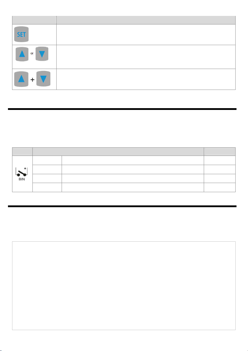
parameter onfiguration methods:
!
!