Bullhorn RM4000 Series RM4010 User manual

Proven compliance solutions.
Relentless service.
RM4000 Series
RM4000 Series
User Guide

Information in this document is subject to change without notice.
© 1999 - 2019 American Innovations, Ltd. All rights reserved.
American Innovations | www.aiworldwide.com | 12211 Technology Blvd | Austin, TX 78727
Reproduction in any manner whatsoever without the written permission of American Innovations is strictly
forbidden.
The American Innovations logo and icon and products are trademarks of American Innovations, Ltd. Other
trademarks and trade names may be used in this document to refer to either the entities claiming the marks
and names or their products. American Innovations, Ltd. disclaims any proprietary interest in trademarks and
trade names other than its own.
Revised August 2019

Contents
RM4000 Series iii
Contents
Chapter 1: Getting Started 1
RM4010, RM4014, RM4011, RM4015, RM4013, RM4016, and RM4020 Unit Overview 1
RM4150 and RM4151 Unit Overview 2
RM4210 and RM4211 Unit Overview 3
Bullhorn Information Line 3
Technical Services 4
Chapter 2: Installation Overview 5
Safety and Equipment Symbols 5
Electrostatic Discharge Precaution 6
Lithium Battery Precautions 7
Bullhorn System Overview 7
Pre-installation Requirements 8
Installation Tools and Equipment 10
Configuration Hardware and Software 11
Chapter 3: Installing Units 12
Mounting on a Metal Pole or Pipe 12
Mounting a Unit on a Flat Surface 13
Using and Installing Conduit 13
Chapter 4: RM4010 and RM4014 Installation 14
RM4010 and RM4014 Unit Overview 14
Before Installing an RM4010 or RM4014 17
Mounting Requirements 18
Mounting Bracket 18
Installation Overview 19
Installing the GPS Antenna 20
Installing the Power Supply 20
Installing the Antenna with Surge Protection 21
Ground Connection 23
Connecting Unit Ground 23
Installing the Satellite Terminal 24
Installing the Relay 26

RM4000 Series
iv
Connecting Input Wires 26
Chapter 5: RM4011 and RM4015 Installation 28
RM4011 and RM4015 Unit Overview 28
Before Installing an RM4011 or RM4015 31
Placement or Mounting Requirements 32
Installation Overview 33
Mounting the RM4011 or RM4015 34
Installing the GPS Antenna 35
Installing the Power Supply 35
Installing an Optional Surge Arrester 36
Ground Connection 37
Installing Ground Connection to Rectifier Frame 37
Installing the Satellite Terminal 38
Installing the Relay 40
Connecting Input Wires 40
Chapter 6: RM4013 and RM4016 Installation 42
RM4013 and RM4016 Unit Overview 42
Before Installing an RM4013 or RM4016 44
Mounting Requirements 45
Mounting Bracket 46
Installation Overview 46
Ground Connection 47
Installing a 1.65 Watt Solar Panel Battery Charger 47
Installing the Satellite Terminal 49
Connecting Input Wires 50
Chapter 7: RM4020 Installation 52
RM4020 Unit Overview 52
Before Installing an RM4020 54
Mounting Requirements 55
Mounting Bracket 55
RM4020 Installation Overview 56
Installing the RM4020 Antenna with Surge Protection 57
Installing an Optional Surge Arrester 58
Ground Connection 60

RM4000 Series
v
Connecting Unit Ground 60
Installing a 1.65 Watt Solar Panel Battery Charger 61
Establishing Communication with Satellite 63
Connecting Input Wires 63
Chapter 8: RM4150 and RM4151 Installation 65
RM4150 and RM4151 Unit Overview 65
Before Installing an RM4150 or RM4151 68
Placement or Mounting Requirements 69
Installation Overview 70
Mounting the RM4150 and RM4151 71
Connecting the GPS and GSM Antennas 71
Connecting the Power Supply 73
Ground Connection 74
Connecting Unit Ground 74
Connecting the Relay 75
Connecting Input Wires 75
Chapter 9: RM4210 and RM4211 Installation 77
RM4210 and RM4211 Unit Overview 78
RM4210 Inputs 78
RM4211 Inputs 79
Unit Dimensions and Communication 80
Before Installing an RM4210 or RM4211 82
Installation Overview 82
Installing the RM4210 83
Installing the RM4211 88
Testing Satellite Reception 93
RM4210 and RM4211 Maintenance 95
Chapter 10: Configuration Overview 96
Universal Configuration Toolkit Software 96
BATtools Suite Installer 97
Microsoft .NET Framework 98
USB Device Driver 98
Installing the UCT and Support Files 98
Bullhorn Tools Software 99
Bullhorn Tools Mobile App 99

RM4000 Series
vi
Chapter 11: RM4010, RM4014, RM4011, RM4015, RM4013, and RM4016
Configuration 100
Configuring the RM4010, RM4014, RM4011, RM4015, RM4013, and RM4016 100
Connecting the Unit and Starting Bullhorn Tools 101
Viewing Unit Information 105
Sending a Test Message 105
Applying a Saved Template 107
Adjusting the Unit Clock 108
Configuring Transmission Settings 109
Setting Battery Information 109
Setting AC Outage Delay 110
Configuring Interruption and Interference 112
Verifying Interruption 115
Enabling or Disabling Readings 117
Configuring Analog Readings 118
Enabling Alarms 120
Configuring Digital Readings 122
Configuring Digital 5 for Accumulator 124
Working with Templates 126
Creating New Templates 127
Importing, Exporting, or Deleting Templates 127
Completing Configuration and Installation 128
Chapter 12: RM4020 Configuration 129
Configuring the RM4020 129
Connecting the Unit and Starting UCT 130
Applying a Saved Template 131
Selecting a Folder for Templates and Log Files 132
Selecting International Gateway 132
Setting the Controller Clock 132
Setting a Transmission Schedule 133
Setting Battery Information 133
Setting an Input Channel for Analog Readings 133
Setting an Input Channel for Digital Readings 136
Transmitting a Test Packet 138
Saving Settings in the Event Log 138
Saving Settings in a Template 139
Completing Configuration and Installation 139

RM4000 Series
vii
Chapter 13: RM4150 and RM4151 Configuration 140
Configuring the RM4150 and RM4151 141
Connecting the Unit and Starting Bullhorn Tools 142
Viewing Unit Information 144
Sending a Test Message 146
Applying a Saved Template 147
Setting a Reporting Schedule 148
Configuring Interruption and Interference 149
Enabling or Disabling Readings 152
Enabling or Disabling Digitals & Accumulators 153
Configuring Readings and Alarm Settings 153
DC or AC 154
Instant Off 157
Readings Graphics 158
Configuring Digital and Accumulator Inputs 159
Editing Power Information 162
Changing SIM Destination 163
Working with Templates 164
Creating Templates 164
Importing, Exporting, or Deleting Templates 165
Upgrading Unit Firmware 166
Completing Configuration and Installation 167
Chapter 14: RM4210 and RM4211 Configuration 168
Configuring the RM4210 or RM4211 168
Activating Bluetooth 169
Connecting to the Unit 170
Viewing Unit Information 172
Loading or Importing a Template 172
Sending a Test Message 173
Setting Transmission and Measurement Schedules 175
Setting Battery Information 179
Editing Setting for Coupon, Transducer, and Instant Off 180
Selecting Reading Measurement Schedules 182
Resetting Over-Current 182
Working with Templates 186
Creating a New Template 186
Importing, Exporting, and Deleting Templates 186
Upgrading RM4210 Firmware 187

RM4000 Series
viii
Completing Configuration and Installation 188
De-activating Bluetooth 188
Appendix A: Optional Installations 189
Precautions for Connecting Optional Components 189
AC Battery Charger 190
Charging RM4010, RM4014, RM4011, RM4015, RM4013, and RM4016 Batteries 191
Charging RM4020 Batteries 191
Installing the Selectable Current Transducer 192
Installing and Connecting a Power Supply 194
Installing and Connecting a Solar Panel 195
Installing the Adjustable Mounting Bracket 197
Chapter B: Battery and Fuse Replacement 199
Replacing the Battery in Latched Enclosure Units 199
Replacing the Battery in Closed Units 202
Replacing the Batteries in Domed Units 205
Replacing the Fuse 206
Appendix C: Technical Specifications 208
RM4010, RM4011, RM4013, RM4014, RM4015, and RM4016 Technical Specifications 208
RM4150 and RM4151 Technical Specifications 209
RM4210 and RM4211 Technical Specifications 210
Appendix D: Mercury Relay Advisory 213
Appendix E: Regulatory Notices 215
FCC Requirements 215
Export Control Classification Number 215
CE Certification 216

1
RM4000 Series 1
Chapter 1: Getting Started
This guide explains how to install and configure Bullhorn RM4000 Series units for service. This guide
includes instructions for installing and configuring units, optional equipment that is available to be
installed with select units, technical specifications for different unit types, and other related
information.
This chapter includes the following topics:
lRM4010, RM4014, RM4011, RM4015, RM4013, RM4016, and RM4020 Unit Overview on page 1
lRM4150 and RM4151 Unit Overview on page 2
lRM4210 and RM4211 Unit Overview on page 3
lBullhorn Information Line on page 3
lTechnical Services on page 4
RM4010, RM4014, RM4011, RM4015, RM4013, RM4016,
and RM4020 Unit Overview
The RM4010, RM4014, RM4011, RM4015, RM4013, RM4016, and RM4020 units monitor oil and gas
assets in cathodic protection (CP) applications. The RM4010 and RM4014 measure the output of
rectifier current across shunt resistors. The RM4014, RM4015, and RM4016 are identical to the
RM4010, RM4011, and RM4013, respectively, except for the use of the SkyWave IDP-680 satellite
terminal, which is replacing the DMR-800 series terminals.
Remote monitoring units use satellite networks for communication with Bullhorn Web. RM4010,
RM4014, RM4011, RM4015, RM4013, and RM4016 (with the capability of two-way communication)
use the SkyWave-Inmarsat satellite network; RM4020 uses the ORBCOMM satellite network. Units
transmit channel measurements and alarms to your website account.
NOTE: Satellite coverage maps are available through the carrier websites, such as ORBCOMM
Satellite.
These units provide built-in surge protection, rectifier interface, and test point filtering functionality.
Additionally the RM4010, RM4014, RM4011, and RM4015 also support GPS synchronized current
interruption, either factory-installed or field-upgraded. These units support six (6) configurable
inputs with the following specifications:
RM4000 Series
Chapter 1: Getting Started 2
lInput Channels 1, 3, and 4 are isolated inputs that support analog ±50 mV, ±5 V DC, 4 to 20
mA with external resistor input devices.
lInput Channel 2 is an isolated input that supports analog ±5 V DC, ±100 V DC, 4 to 20 mA with
external resistor input devices.
lInput Channels 5 and 6 are non-isolated inputs that support 0 - 15 V DC digital input devices.
Channel 5 can also be used as a pulse count accumulator.
RM4150 and RM4151 Unit Overview
The RM4150 and RM4151 remote monitoring units monitor oil and gas assets in cathodic protection
(CP) applications using various communication networks for communication with Bullhorn Web.
NOTE: Satellite coverage maps are available through the carrier websites, such as ORBCOMM
Satellite.
The RM4150 and RM4151 units provide built-in surge protection, rectifier interface, and test point
filtering functionality. The RM4150 and RM4151 measure the output of rectifier current across shunt
resistors. Additionally, the RM4150 and RM4151 support GPS synchronized current interruption.
The RM4150 supports two (2) configurable digital and five (5) configurable analog inputs with the
following specifications:
lInput ANALOG CH 1 through ANALOG CH 5 (channels 1 through 5) are isolated inputs that
support analog ±150 V DC, 150 V AC, 4 - 20 mA with external resistor, or active digital input
devices.
lInput DIGITAL CH 1 and DIGITAL CH 2 non-isolated inputs (0-24 V DC) that support digital dry
contact closure input devices. DIGITAL CH 1 can also be used as a pulse count accumulator,
and DIGITAL CH 2 can be used as an accumulator reset.
The RM4151 supports two (2) configurable digital and two (2) configurable analog inputs with the
following specifications:
lInput ANALOG CH 1 and ANALOG CH 2 (channels 1 and 2) are isolated inputs that support
analog ±150 V DC, 150 V AC, 4 - 20 mA with external resistor, or active digital input devices.
lInput DIGITAL CH 1 and DIGITAL CH 2 non-isolated inputs (0-24 V DC) that support digital dry
contact closure input devices. DIGITAL CH 1 can also be used as a pulse count accumulator,
and DIGITAL CH 2 can be used as an accumulator reset.

RM4000 Series
Chapter 1: Getting Started 3
RM4210 and RM4211 Unit Overview
The RM4210 and RM4211 remote monitoring units monitor oil and gas assets in cathodic protection
(CP) applications. The units utilize various satellite/GSM communication networks for
communication with Bullhorn Web, the web-based asset manager where measurements can be
monitored and used to optimize AC mitigation systems. Reports and extracts are also available
through the Bullhorn Web account to view the data from your units.
Satellite coverage maps are available through the carrier websites, such as ORBCOMM Satellite.
The RM4210 and RM4211 units provide built-in surge protection and test point filtering
functionality. The units are fully-integrated and are usually mounted on top of a test station. All
components, including the antenna, are internal to make it easier to transport, install, and maintain.
The RM4210 can measure induced AC voltage, AC current, and associated current density, which can
be present on pipelines that are co-located with high voltage AC power lines.
The RM4211 includes three high-voltage analog measurement channels that work across a variety of
applications to capture measurements such as AC/DC pipe-to-soil, instant-off, shunts, and rectifier
Volts and Amps.
Measurements are automatically uploaded via satellite communication to Bullhorn Web.
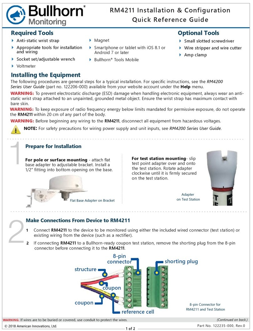
The RM4210 inputs can be measured and configured locally using either the Bullhorn Tools software
on a laptop or with the mobile application on a smartphone or tablet running either iOS or Android.
The RM4211 can be configured only with the mobile app. The Bullhorn Tools software is available
for download from the Bullhorn Tools launch page, and the mobile app is available through the
Apple App Store or Google Play.
Bullhorn Information Line
The Bullhorn Information Line is an automated attendant telephone system. It is typically used when
installing units in the field. The system identifies when the last data transmission (or test packet) was
received on your website account for a unit you specify.
Complete the following steps to use the Bullhorn Information Line:
1. Call the Bullhorn Information Line at 866-287-6739.
2. Press 1 to access the packet log when prompted.
3. Use your telephone keypad to enter the unit serial number when prompted. The unit serial
number is included on the bar code label on the unit. It is also included on the label of the
shipping carton. If required, repeat this step to check another unit.

RM4000 Series
Chapter 1: Getting Started 4
Technical Services
AI Technical Support is available to provide assistance with Bullhorn Remote Monitoring Units,
accept feedback about Bullhorn Remote Monitoring Units, or discuss your organization’s training
needs. Use the following information to contact AI Technical Support:
Telephone:
1-800-229-3404
Email:
support@aiworldwide.com
Address:
American Innovations, Ltd.
Attn: AI Technical Support
12211 Technology Blvd.
Austin, TX 78727

2
RM4000 Series 5
Chapter 2: Installation Overview
The following unit types are included in the RM4000 Series:
lRM4010 / RM4014
lRM4011 / RM4015
lRM4013 / RM4016
lRM4020
lRM4150
lRM4151
lRM4210
lRM4211
Pre-installation considerations and precautions, such as installation tools and electrostatic discharge
(ESD) precautions, pertain to all unit types. However, units are installed according to their monitoring
purpose. Refer to the following sections for details on how to install a specific unit type:
lRM4010 and RM4014 Installation on page 14
lRM4011 and RM4015 Installation on page 28
lRM4013 and RM4016 Installation on page 42
lRM4020 Installation on page 52
lRM4150 and RM4151 Installation on page 65
lRM4210 and RM4211 Installation on page 77
Safety and Equipment Symbols
WARNING: If a Bullhorn remote monitoring unit is used in a manner not specified by AI, the
protection provided for the equipment may be impaired.
The following table provides a description of various safety and equipment symbols. Safety symbols
alert you to safety hazards or conditions that have the potential to cause personal injury, death, or

RM4000 Series
Chapter 2: Installation Overview 6
equipment damage. Equipment symbols may indicate a functional state (such as on and off) and
connections (such as a Earth ground terminal).
Symbol Description
Caution — Failure to observe this warning may result in personal injury, death,
or equipment damage. A potential risk exists if the installation instructions are
not followed.
Warning — Risk of electrical shock. Failure to observe this warning may result
in personal injury, death, or equipment damage. A potential risk exists if the
installation instructions are not followed.
Earth (ground) terminal — Indicates a protective earth ground connection is
required.
On (Supply) — Indicates power is on when the toggle switch is in the "ON"
position.
Off (Supply) — Indicates power is off when the toggle switch is in the "OFF"
position.
DC power — Indicates that the input requires DC power.
AC/DC — Both direct and alternating current.
Positive — Indicates a positive input.
Negative — Indicates a negative input.
Table 2-1. Safety and Equipment Symbols
Electrostatic Discharge Precaution
Electrostatic Discharge (ESD) can damage electronic components. To prevent ESD damage when

RM4000 Series
Chapter 2: Installation Overview 7
handling electronic equipment, always wear an anti-static wrist strap attached to an unpainted,
grounded metal object. Ensure the wrist strap has maximum contact with bare skin. If an anti-static
wrist strap is available, discharge static electricity from yourself and your clothing by touching a
grounded metal object before handling electronic equipment.
Lithium Battery Precautions
WARNING: To protect against personal injury or damage to the lithium battery, observe the
following precautions prior to using the battery.
Lithium batteries may get hot, explode, or ignite and cause serious injury if exposed to abuse
conditions. Make sure to observe the following safety warnings:
lDo not install the battery backwards. This will cause the polarity to be reversed.
lDo not connect the positive terminal and negative terminal of the battery to each other with
any metal object (such as wire).
lDo not carry or store the battery together with bracelets, necklaces, rings, or other metal
objects.
lDo not pierce the battery with nails, strike the battery with a hammer, step on the battery, or
otherwise subject it to strong impacts or shocks.
lDo not place the battery in fire or heat the battery.
lDo not solder directly onto the battery.
lDo not expose the battery to water or salt water, or allow the battery to get wet.
lDo not disassemble or modify the battery. The battery contains safety and protection devices,
which, if damaged, may cause the battery to generate heat, explode, or ignite.
lDo not place the battery in or near fire, on stoves, or other high temperature locations.
lDo not place the battery in direct sunlight. Doing so may cause the battery to generate heat,
explode, or ignite. Using the battery in this manner may also result in a loss of performance
and a shortened life expectancy.
Bullhorn System Overview
Bullhorn is a wireless telemetry system that provides scheduled and by-exception inbound reporting
for field equipment typically located in remote areas. Data and alarm packets transmit from remote
field locations to your account on the secure Bullhorn Web using digital cellular or satellite

RM4000 Series
Chapter 2: Installation Overview 8
communication networks. You can quickly determine the status of field equipment anytime using
information that posts to your website account.
The Bullhorn system provides remote monitoring with full coverage using GSM cellular network,
GEOS satellite (SkyWave-Inmarsat), or LEOS satellite (ORBCOMM) communication networks.
Pre-installation Requirements
Before you install any Bullhorn remote monitoring unit, use the following information as a checklist
to ensure a successful installation:
Power Disconnect and Branch Circuit Protection — A customer-supplied, power disconnect
device is required for the unit installation. The power disconnect device (such as a switch, main
circuit breaker, or other type of power disconnect) should provide an easy and accessible means for
removing the main input supply power source from the unit. Multiple-pole circuit breakers shall
interrupt all neutral and ungrounded connectors of mains supply simultaneously. The power
disconnect device must be clearly marked to identify it as the disconnect device for the unit. The
power disconnect or separate over-current protection device should also provide over-current
protection in the form of a 20 amp fuse or circuit breaker suitable for branch circuit protection per
local codes and requirements.
Backup Battery — Remote monitoring units that use a backup battery must have the batteries
replaced with batteries of same voltage. To ensure this, only use batteries supplied by American
Innovations.
lThe RM4010 and RM4014 should only be used with a 12 V DC, 3.4 AH capacity, re-chargeable
sealed lead acid battery (American Innovations part number 370042-000; manufacturer's part
number PS-1230).
lThe RM4011 and RM4015 should only be used with a 12 V DC, 2.0 AH capacity, re-chargeable
sealed lead acid battery (American Innovations part number 370149-000; manufacturer's part
number PS-1221S).
lThe RM4013 and RM4016 should only be used with a 12 V DC, 3.4 AH capacity, re-chargeable
sealed lead acid battery (American Innovations part number 370042-000; manufacturer's part
number PS-1230).
lThe RM4150 and RM4151 should only be used with a 12 V DC, 0.8 AH capacity, re-chargeable
sealed lead acid battery (American Innovations part number 370109-000; manufacturer's part
number PS-1208).
lThe RM4210 and RM4211 should only be used with a 7.2 V 2.0 Ah Li-ion re-chargeable battery
and a 3.6 V 13.0 AH capacity battery (sold separately or as a pair with American Innovations
part number 517206-000).

RM4000 Series
Chapter 2: Installation Overview 9
Please contact AI Sales for information about purchasing replacement batteries.
NOTE: Refer to Battery and Fuse Replacement on page 199 for instructions on changing the backup
battery.
Wiring Requirements — For optimum protection from transient voltages (typically, Channels 1
and 2), all analog inputs must be in their own multi-conductor jacket cable (such as cable AI part
number 211061-000 - Belden 5308UE, or its equivalent). All cables must have intact outer jackets,
except for end cuts. Do not remove cable jackets as they protect the unit input cable from transient
voltages. Cable insulation should be suited for voltage range of inputs. Cables should be rated at a
minimum of 600 V and 105° C.
Input Channel Voltage Levels — All input channels are marked with acceptable input voltage
ranges. Ensure that devices connected to the unit fall within the voltages ranges listed next to the
channel input connections.
Cellular Radio Transmitter — The RM4150 and RM4151 contain a cellular radio transmitter, and
usage may be dangerous in environments such as:
lWhere it can interfere with other electronic devices in environments such as hospitals, airports,
aircraft, etc.
lWhere there is risk of explosion such as gasoline stations, oil refineries, etc.
lThe antenna has to be installed with care in order to avoid any interference with other
electronic devices and has to be guaranteed a minimum distance from the body (20 cm). In
the event that this requirement cannot be satisfied, the system integrator has to assess the
final product against the SAR regulation.
lIt is the responsibility of the user to enforce the country regulation and the specific
environment regulation.
Earth (ground) terminal — Indicates a protective earth ground connection is required.
Antenna Installation — The dual GSM/GPS antenna should be placed outside the rectifier.
Mounting the Enclosure — Choose an area that provides enough room to easily access the unit or
to perform routine maintenance after completing the installation. Use the information in the specific
unit installation sections when deciding where to install the unit.
WARNING: Equipment intended to be mounted on a wall or ceiling shall withstand a force of four
times (4x) the weight of the equipment.
Placing the Enclosure — Place the RM4150 and RM4151 inside the rectifier, either by placing it on

RM4000 Series
Chapter 2: Installation Overview 10
the floor of the rectifier case or by attaching magnets to the unit and securing to an available area.
Choose an area that provides enough room to easily access the unit or to perform routine
maintenance after completing the installation.
WARNING: Only accessories that meet American Innovations specifications may be used with the
units.
Installation Tools and Equipment
WARNING: Equipment intended to be mounted on a wall or ceiling shall withstand a force of four
times (4x) the weight of the equipment.
Depending on the unit type, the following tools and equipment are required for installing and
configuring units for service:
lanti-static wrist strap
lsmall slotted screwdriver
lsmall Phillips head screwdriver
lwire stripper
lwire cutter
lvoltmeter
ladjustable wrench (for solar panel battery charger installation)
lsocket or open end wrench set
lcompass
lwaterproof sealing tape
lsilicon adhesive
lmounting hardware (appropriate type for mounting surface; supplied by customer)
lappropriate tools for preparing the mounting surface for installation (such as a hand drill and
metal, masonry, or wood drilling bit)
linstallation drawing (provided in installation kit)
lconfiguration cable (provided in installation kit; standard mini USB cable typically used with

RM4000 Series
Chapter 2: Installation Overview 11
most digital cameras)
lmagnet (to activate units with Bluetooth connections)
Configuration Hardware and Software
To configure a unit in the field, you can use either of the following:
lA computer running Microsoft Windows with the following hardware and software
specifications:
— Pentium processor or equivalent
— 2 GB RAM (minimum)
— 400 MB free hard drive space (minimum)
— Spare USB port
— Microsoft Windows Vista Home Premium, Business, or Ultimate with Service Pack 1 or
higher; or Windows 7 Home Premium, Professional, or Ultimate
— Bullhorn Tools configuration software (available for download through the Bullhorn
Tools launch page) and the AI USB Bluetooth dongle
— Windows Internet Explorer version 8.0 or higher
— Adobe Reader version 6.0 or higher
lA smartphone or tablet with the following:
— iOS iOS8 or Android 7
— Bluetooth
— Bullhorn Tools Mobile application, available through the Apple App Store or Google
Play
While the RM4210 can be configured with either the software version or mobile app, the RM4211
can only be configured with the mobile version of Bullhorn Tools. Instructions for using Bullhorn
Tools Mobile to configure the RM4210 are available in the Bullhorn Tools Mobile App User Guide.
Refer to RM4210 and RM4211 Configuration on page 168 for more information.

3
RM4000 Series 12
Chapter 3: Installing Units
Refer to the following topics for unit-specific installation instructions:
lRM4010 and RM4014 Installation on page 14
lRM4011 and RM4015 Installation on page 28
lRM4013 and RM4016 Installation on page 42
lRM4020 Installation on page 52
lRM4150 and RM4151 Installation on page 65
lRM4210 and RM4211 Installation on page 77
Some of the Bullhorn remote monitoring units can be mounted on various external locations,
depending on the installation area and available surfaces. Refer to the following topic for
information on nonstandard installation methods:
lMounting on a Metal Pole or Pipe on page 12
lMounting a Unit on a Flat Surface on page 13
Mounting on a Metal Pole or Pipe
Some units are shipped with a mounting hardware kit that includes one (1) u-bolt , one (1) bolt, and
mounting hardware (4 nuts and 4 washers for the u-bolt). The typical installation is on a free-
standing metal pole or pipe using the included mounting hardware kit.
NOTE: The u-bolt used to mount the unit may be a maximum of 2" on center with 1/4-20. Pipe can
be no greater than 1-3/4" OD.
Complete the following steps to install the unit's enclosure on a metal pole or pipe:
1. Run one u-bolt around the pole, through the pipe bracket, and then through the top of the
mounting bracket.
2. Slide a washer over and thread a nut onto each end of the u-bolt and tighten each nut.
3. Repeat previous steps for the bottom of the mounting bracket.
Other manuals for RM4000 Series RM4010
1
This manual suits for next models
10
Table of contents
Other Bullhorn Measuring Instrument manuals

Bullhorn
Bullhorn RM4200 Series User manual

Bullhorn
Bullhorn RM5 I/O4 User manual

Bullhorn
Bullhorn RM4000 Series RM4010 User manual

Bullhorn
Bullhorn SDT16 Family Operator's manual

Bullhorn
Bullhorn RM1250 User manual

Bullhorn
Bullhorn RM4150 User manual

Bullhorn
Bullhorn RM4150 User manual

Bullhorn
Bullhorn RM4200 Series User manual

Bullhorn
Bullhorn RM4211 User manual