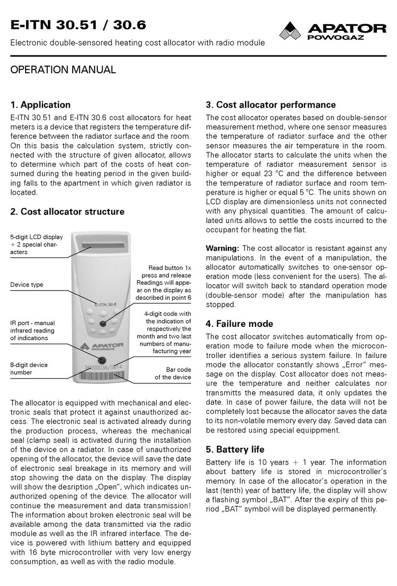
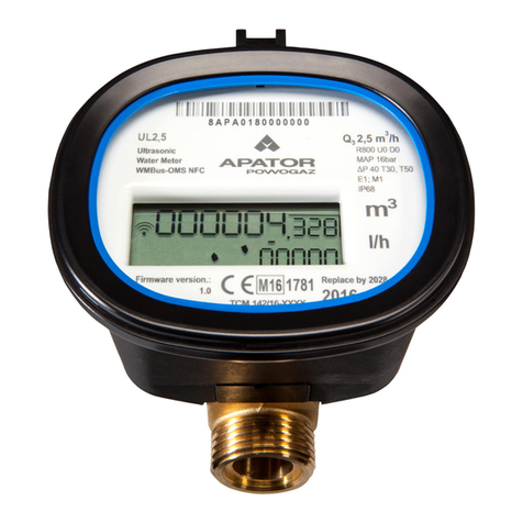
Apator FAUN D204MB Manual

PLEN
Apator SA
ul. Gdańska 4a lok. C4, 87-100 Toruń, Poland
e-mail: apator@apator.com
www.apator.com
FAUN
Instrukcja instalacji i obsługi
Installation and Setup Instructions
175 °C

PL EN
FAUN IP54 FAUN IP65 FAUN IP68
159 mm
100 mm
82
68
159 mm
100 mm
123 mm
159 mm
100 mm
123 mm
46
54

PL
Montaż przelicznika
Montaż przelicznika na ścianie
1. Zdejmij podstawę montażową A (rys. 1) z przelicz-
nika, przesuwając ją w kierunku odwrotnym niżwi-
doczne na niej strzałki.
2. Nanieś na ścianę rozmieszczenie otworów pod kołki
montażowe wg wymiarów przedstawionych na rys. 2
bądź przykładając podstawę montażową do ściany.
3. Wywierć otwory pod kołki montażowe, używając
wiertła ø6 dostosowanego do podłoża.
4. Umieść załączone kołki montażowe w wywierco-
nych otworach.
5. Przyłóż podstawę montażową A do ściany w taki
sposób, aby otwory w podstawie montażowej po-
krywały się z umieszczonymi w otworach kołkami
montażowymi.
6. Przymocuj podstawę do ściany, używając załączo-
nych wkrętów.
7. Nasuń przelicznik na zamocowaną podstawę mon-
tażową zgodnie zrys. 3.
8. Odkręć śruby B przytrzymujące pokrywę przeliczni-
ka (rys. 4).
9. Zdejmij pokrywę przelicznika C (rys. 5).
10. Dokonaj podłączeń elektrycznych zgodnie zopisem
zamieszczonym w dziale „Podłączenia elektryczne”.
11. Nałóż pokrywę C z powrotem na podstawę przelicz-
nika.
12. Przykręć pokrywę C do podstawy przelicznika śruba-
mi B.
13. Załóż plomby (rys. 6 - drutowe, rys. 7 - naklejane).
Montaż przelicznika na przetworniku
ultradźwiękowym
Przetwornik ultradźwiekowy Sharky 473
1. Usuń podstawę montażową A (rys. 1) z przelicznika,
przesuwając ją w kierunku odwrotnym niżwidoczne
na niej strzałki.
2. Nałóż przelicznik na gniazdo montażowe w prze-
tworniku ultradźwiękowym (rys. 8).
3. Przesuń przelicznik w kierunku otworów kablowych,
aż do momentu zatrzaśnięcia się przelicznika na
przetworniku.
4. Postępuje zgodnie z punktami 8-13 opisanymi
wprzypadku montażu przelicznika na ścianie.
Przetworniki Ultraflow
1. Zdejmij podstawę montażową A (rys. 1) z przelicz-
nika, przesuwając ją w kierunku odwrotnym niżwi-
doczne na niej strzałki.
2. Nałóż podstawę montażową na gniazdo montażowe
w przetworniku ultradźwiękowym.
3. Przesuń podstawę montażową w kierunku odwrot-
nym niż widoczne na niej strzałki, aż do momentu
zatrzaśnięcia się podstawy montażowej na przetwor-
niku.
4. Postępuje zgodnie z punktami 7-13 opisanymi
wprzypadku montażu przelicznika na ścianie.
A
Rys. 1.
70,5 mm
73,5 mm
4 x 4,5 mm
36,5 mm
39,5 mm
53,5 mm
B
B
Btylko IP68
Btylko IP68
przetwornik
ultradźwiękowy
C
Rys. 2. Rys. 3.
Rys. 4.
Rys. 6.
Rys. 7. Rys. 8.
Rys. 5.

PL
Podłączenia elektryczne
W celu dokonania podłączeń elektrycznych należy zdjąć
pokrywę przelicznika C (rys. 5). Sposób zdejmowania
został opisany w dziale „Montaż przelicznika”.
Podłączanie czujników temperatury
Pomiar temperatury może być wykonywany za pomocą
współpracującego z przelicznikiem czujnika Pt500,
zarówno 2-, jak i 4-przewodowych. W zależności od
ilości przewodów przyłączeniowych czujników
temperatury dostępne są dwa wykonania listwy złącz
(rys. 9) przelicznika:
Rys. 9.
– przelicznik zlistwą do 2-przewodowego czujnika po-
miaru temperatury, listwą do podłączenia głównego
przetwornika przepływu oraz listwą do podłączenia 4
dodatkowych urządzeń (rys. 10),
Rys. 10.
– przelicznik zlistwą do 4-przewodowego czujnika po-
miaru temperatury, listwą do podłączenia głównego
przetwornika przepływu oraz listwą do podłączenia 4
dodatkowych urządzeń (rys. 11).
Rys. 11.
-
Podłączanie przetwornika przepływu
Do podłączenia głównego przetwornika przepływu służy
3-zaciskowe złącze, oznaczone numerami:
9 – wyjście zasilania dla przetwornika przepływu
(zgłównego źródła zasilania),
10 – wejście sygnałowe dla przetwornika przepływu,
11 – wyjście odniesienia sygnału przetwornika przepływu.
Dodatkowo istnieje możliwość podłączenia przewodu
komunikacyjnego przetwornika przepływu do wejścia
sygnałowego – czwartego wejścia dodatkowego (zacisk
53) (tylko jeżeli jest ono skonfigurowane jako wejście
cyfrowe komunikacji z przetwornikiem).
Rys. 12.
-Na rys. 12 przedstawiono sposób podłączenia przetwor
ników przepływu, zwyjściem typu otwarty kolektor dla
przetwornika zwymaganym zasilaniem zprzelicznika
(1), wyjściem typu otwarty kolektor (2) oraz wyjściem
typu styk zwierny (3).
Podłączanie przetwornika przepływu z nadajnikiem NC
- polaryzacja podłączenia dowolna (rys. 13)
Rys. 13.
BRĄZOWY
BIAŁY
Podłączanie przetwornika ultradźwiękowego Sharky 473.
Rys. 14.
BRĄZOWY
BIAŁY
NIEBIESKI
ŻÓŁTY
Podłączanie przetwornika ultradźwiękowego Ultraflow.
Rys. 15.
CZERWONY
ŻÓŁTY
NIEBIESKI
Uwaga: w przypadku przetworników ultradźwiękowych z
4-ro przewodowym podłączeniem (np. Sharky 473) czwarty
przewód (żółty) może być podłączony do Fauna tylko jeżeli
jego wejście I4 jest skonfigurowane jako wejście cyfrowe
komunikacji z przetwornikiem. W przeciwnym razie nie
podłączać tego przewodu. Nieprawidłowe podłączenie
może skutkować przedwczesnym zużyciem baterii.
W przypadku pomiaru czujniami 2-przewodowymi (rys.
10) czujnik T1 (temperatury zasilania) należy podłączyć
do złącza oznaczonego numerami: 5, 6, czujnik T2 (tem
peratury powrotu) do złącza: 7, 8. Wprzypadku pomiaru
czujnikami 4-przewodowymi (rys. 11) czujnik T1 należy
podłączyć do złącza oznaczonego numerami: 5, 6 oraz
1, 2, natomiast czujnik T2 do złącza: 7, 8 oraz 3, 4.

PL
Podłączanie dodatkowego przetwornika
przepływu
Dodatkowy przetwornik przepływu może być wykorzysta-
ny do wykrywania nieszczelności w instalacjach pracu-
jących w systemie zamkniętym, należy go podłączyć do
wejścia dodatkowego 3. Do podłączenia przetwornika
służy 2 zaciskowe złącze (rys. 16), oznaczone numerami:
54 – wejście sygnałowe dla dodatkowego przetwornika
przepływu,
50 – wyjście odniesienia sygnału dodatkowego prze-
twornika przepływu.
Dodatkowo istnieje możliwość podłączenia wejścia
komunikacyjnego przetwornika oraz zasilania:
9 – wyjście zasilania dla przetwornika przepływu
(zgłównego źródła zasilania),
55 – wejście sygnałowe do komunikacji z dodatkowym
przetwornikiem przepływu (wejście dodatkowe 2)
(tylko jeżeli jest ono skonfigurowane jako wejście
cyfrowe komunikacji z przetwornikiem).
Poniżej przedstawiono sposób podłączenia dodatko
wego przetwornika przepływu, z wyjściem typu otwarty
kolektor dla przetwornika z wymaganym zasilaniem z
przelicznika (1), wyjściem typu otwarty kolektor (2) oraz
wyjściem typu styk zwierny (3).
Rys. 16.
Podłączanie zewnętrznego zasilania
Przelicznik może być zasilany z zasilacza 230V AC albo
24V AC, jak również za pomocą baterii typu AA, dwóch
baterii AA lub C montowanych na dodatkowej płytce lub
baterii typu D montowanej bezpośrednio wpodstawie.
Po otwarciu pokrywy możliwy jest bezpośredni dostęp
do głównej baterii lub zasilacza (rys. 19). W przypadku
samodzielnej wymiany baterii typu D należy zwrócić
uwagę na sposób jej montażu w obudowie, biegun
dodatni powinien być zwrócony w kierunku górnej
krawędzi obudowy. Każda zbaterii lub zasilacz ma wy
prowadzone przewody do podłączenia do przelicznika.
Zasilanie główne należy podłączyć na listwie zaciskowej
(rys. 9) do złącza oznaczonego cyframi: 60 – biegun
dodatni, 61 – biegun ujemny.
W przypadku przelicznika wyposażonego w zasilacz: dla
zasilacza sieciowego należy doprowadzić do niego zasi
-
-
-
-
lanie ~230 V ipodpiąć pod zaciski oznaczone cyframi:
27 i 28 (rys. 18) dla zasilacza 24 V doprowadzić zasilanie
~24 V do zacisków oznaczonych cyframi:97, 98 (rys. 19).
Zasilacz posiada dwie pary zacisków oznaczonych cy
frami 95 i 96, umożliwiających zasilanie wymiennych
modułów komunikacyjnych (zaciski na modułach ozna
czone cyframi 97 i 98). Podłączeń elektrycznych zasila
cza sieciowego powinna dokońać osoba posiadająca
stosowne uprawnienia.
Rys. 17.
Rys. 18. Rys. 19.
97
24VA C
98
Podłączanie sygnałów wejść dodatkowych
W każdym z wykonańgłównej listwy zaciskowej dostęp-
ne są4 dodatkowe wejścia. Każde z wejść oznaczonych
symbolami I1 (zaciski nr 56 i50), I2 (zaciski nr 55 i 50),
I3 (zaciski nr 54 i 50), I4 (zaciski nr 53 i 50) może pra-
cować jako wejście impulsowe, a dodatkowo wejście I3
może służyć jako wejście alarmowe bądź do podłączenia
dodatkowego przetwornika przepływu, a wejścia I2 i I4
mogá być wykorzystane do cyfrowej komunikacji z prze-
twornikiem przepływu.
Każde z wejść ma dwa zaciski, oznaczone następująco:
– wejście sygnałowe (zaciski nr 56, 55, 54, 53)
– wejście odniesienia dla wejścia dodatkowego,każde
z wejść ma osobny zacisk do podłączenia sygnału
odniesienia (zaciski nr 50).
Rys. 20.
Uwaga: w przypadku przetworników ultradźwiękowych z 4-ro
przewodowym podłączeniem (np. Sharky 473) czwarty
przewód (żółty) może być podłączony do Fauna tylko jeżeli
jego wejście I2 jest skonfigurowane jako wejście cyfrowe
komunikacji z przetwornikiem. W przeciwnym razie nie
podłączać tego przewodu. Nieprawidłowe podłączenie może
skutkować przedwczesnym zużyciem baterii.
-
-

PL
Na rys. 20 przedstawiono sposób podłączenia sygnału
dla przykładowego, jednego z wejść dodatkowych, dla
urządzenia z wyjściem typu: otwarty kolektor (1), styk
zwierny (2).
Montaż modułów dodatkowych
Przelicznik umożliwia zamontowanie maksymalnie
dwóch niezależnych modułów dodatkowych:
– M-Bus
– RS232
– RS485
– wyjść impulsowych (2 wyjścia klasy OB, OC, lub OD)
– wyjść i wejść impulsowych (2 wyjścia klasy OB, OC,
lub OD i 2 wejścia klasy IB lub IC)
– wyjść analogowych (2 wyjścia, 4-20 mA lub 0-10V)
– LonWorks
– radiowy do systemów telemetrycznych IMR (AIUT)
– radiowy Wireless M-Bus.
Rys. 21.
Na rys. 21 przedstawiono miejsce isposób montażu
modułów dodatkowych. Moduły mogą być montowane
w dowolnym złączu za wyjątkiem modułów radiowych,
które mogą być montowane tylko w złączu oznaczonym
numerem 1 (rys. 12).
Montaż modułu M-Bus
(module code: 001)
Moduł M-Bus zasilany jest z sieci M-Bus i odseparo-
wany galwanicznie od przelicznika za pomocą izolacji
optycznej. Moduł obsługuje adresację pierwotną, wtór-
ną oraz wtórną rozszerzoną. Do podłączenia sygnałów
magistrali M-Bus służą wejścia oznaczone numerami
24, 25 (rys. 22).
Montaż modułu RS 232
(module code: 003)
Moduł RS 232 wymaga zewnętrznego źródła zasilania.
Jest odseparowany galwanicznie od przelicznika za po-
mocą izolacji optycznej. Moduł może być zasilany napię-
ciem stałym lub przemiennym. Do podłączenia źródła
zasilania służą zaciski: 97, 98, polaryzacja podłączanego
zasilania jest dowolna. Do podłączenia przewodów
komunikacyjnych służą zaciski: 64 – masa sygnału, 63
– wyjść TxD modułu, 64 – wejście RxD modułu (rys. 23).
Rys. 22. Rys. 23.
WYK.
MBUS
24 2 5
WYK.
RS232
Vin
8...30V
6...30V
97 9 864 6 3 62
GND TxD RxD
Rys. 24. Rys. 25.
WYK.
RS485
Vin
8...30V
6...30V
97 9 886 8 5 84
GND A+ B-
A B
GDN Vcc
Montaż modułu RS 485 (module code: 003)
Moduł RS 485 wymaga zewnętrznego źródła zasilania.
Moduł nie ma izolacji galwanicznej pomiędzy
zasilaczem a magistralą RS485 i należy zachować
szczególną uwagę przy podłączaniu różnych urządzeń
do magistrali. Jest odseparowany galwanicznie od
przelicznika za pomocą izolacji optycznej. Moduł
może być zasilany napięciem stałym lub
przemiennym. Do podłączenia źródła zasilania służą
zaciski: 97, 98, polaryzacja podłą-czanego zasilania jest
dowolna. Do podłączenia przewo-dów komunikacyjnych
służą zaciski: 86 – masa sygnału, 85 – wejście/wyjście A
+(nieodwracające), 84 – wejście/wyjście B–
(odwracające) (rys. 24).
Montaż modułu LonWorks( module code: 002)
Moduł LonWorks (rys. 25) wymaga zewnętrznego źródła
zasilania. Moduł może być zasilany prądem stałym
napięciu w zakresie 9 - 24 V. Do podłączenia źródła
zasilania służy para zacisków znajdujących się w prawej
górnej części modułu oznaczonej jako B. Zacisk
dodatni oznaczony jest jako Vcc, a biegun ujemny jako
GDN. Do podłączenia przewodów komunikacyjnych
służy para zacisków znajdujących się w lewej górnej
części modu-łu oznaczonych jako A - polaryzacja
dowolna.
Montaż modułu Wireless M-Bus
(module code: 004)
Moduł Wireless M-Bus (rys. 26) wyposażony jest w za-
silanie bateryjne oraz posiada własną antenę, dlatego
w celu prawidłowego działania modułu wystarczy
umie-ścić go w odpowiednim złączu.
UWAGA! Moduły Wireless M-Bus mogą być montowa-
ne tylko w złączu oznaczonym numerem 1 (rys. 9).
Sposób podłączenia
wielu urządzeń
na magistrali RS-485
RS485
FAUN
DEV2 A
B
GND
DEVn
ABGND
A
B
GND
A
B
GND

PL
Rys. 26. Rys. 27.
2
1
6
5
2
1
6
5
34 35
SW1
+31 -32
Rys. 28. Rys. 29.
2
1
71 72
01 02
73 74
WYK.2xOUT
9897
6
5
Vin
8 ...30V
6 ...30V
2
1
71 72
01 02 I1 I2
73 74 65
WYK.
2xOUT
2xIN
66 67 68
6
5
9897
Vin
8 ...30V
6 ...30V
Montaż modułu IMR
(module code: 005)
Dostępne są trzy rodzaje modułów IMR (rys. 27): z in-
terfejsem radiowym (wyk. APAT 1312), z interfejsem
radiowym i kablowym (wyk. APAT 1322), z interfejsem
kablowm (wyk. APAT 1332). Moduły mogą być zasilane,
w zależności od wykonania, z własnego zasilania ba-
reryjnego lub zewnętrznego źródła. Interfejs kablowy
(zaciski nr 34 i 35) może zostać wykorzystany do pod-
łączenia aktywnej anteny AMPLI - kolejność przewo-
dów nie ma znaczenia. Do podłączenia zewnętrznego
źródła zasilania (w zakresie 4 - 16 V bądź stabilizownego
3,6 VDC) służą zaciski: 31 - biegun dodatni, 32 - biegun
ujemny. Moduł dostarczany przez producenta w wersji
z własnym zasilaniem znajduje się w trybie uśpienia.
Uruchomienie modułu APAT 13x2 następuje za pomo-
cą przycisku diagnostycznego SW1 (przytrzymć przez
okres od 5 do 7 sekund, a następnie puścić). Jeśli
APAT13x2 to wersja bez własnego zasilania lub układ
jest wybudzony, to celem weryfikacji działania należy
przytrzymać przycisk diagnostyczny przez okres 5 se-
kund. Poprawny tryb pracy zostanie zasygnalizowany
4-krotnym mignięciem diody LED.
UWAGA! Moduły IMR mogą być montowane tylko
wzłączu oznaczonym numerem 1 (rys. 9).
Montaż modułu wyjść/wejść impulsowych
Dostępne są dwa rodzaje modułów wejść/wyjść impul-
sowych. Moduły mogą być zasilane, w zależności od
wykonania, z przelicznika lub zewnętrznego źródła.
1) moduł 2 wyjścia impulsowe (rys. 28, kod modułu:
016): wyjścia impulsowe mogą pracować w różnych
klasach: OB, OC oraz OD według PN-EN 1434-2
(klasa konfigurowana na etapie produkcji).
2) moduł 2 wyjścia + 2 wejścia impulsowe (rys. 29,
kod modułu: 080): wyjścia dla modułu wejść/wyjść
mają takie same wykonania jak dla modułu 016.
Wejścia mogą pracować w klasie IB lub IC (według
PN-EN 1434-2). W każdym z przypadków wejścia
oraz wyjścia są odizolowane galwanicznie od prze-
licznika.
Z uwagi na duży średni pobór prądu zaleca się stoso-
wanie modułów w wykonaniach z zasilaniem zewnętrz-
nym. W każdym z przypadków wyjścia są odizolowane
galwanicznie odprzelicznika,
Typ oraz rozdzielczość każdego z wyjść impulsowych
może być dowolnie skonfigurowana. Wyjście generuje
impulsy, których liczba jest proporcjonalna do przy-
rostu energii lub objętości (głównej, dodatkowej lub
taryfowych), z jedną z trzech rozdzielczości: 0.1, 1, 10.
Do podłączenia zewnętrznego źródła zasilania służą
zaciski: 97, 98, polaryzacja zasilania jest dowolna. Do
podłączenia wejść impulsowych służą zaciski: 65, 66
oraz 67, 68, natomiast do podłączenia sygnału z wyjść
impulsowych zaciski: 71, 72 oraz 73, 74.
Montaż modułu 2 wyjść analogowych
(module code: 256)
Moduł wyjść analogowych wymaga zewnętrznego zasi-
lania i ma separację galwaniczną między przelicznikiem
a modułem. Moduł dostępny jest w trzech wykonaniach
z dwoma wyjściami prądowymi 0/4 ... 20 mA, dwoma
wyjściami napięciowym 1 ... 10 V albo jednym wyjściem
prądowym oraz jednym napięciowym. Wyjścia ana-
logowe mogą być dowolnie skonfigurowane tak, aby
wystawiać stan proporcjonalny do jednej z wartości
chwilowej: przepływu, mocy, temperatury zasilania,
powrotu albo różnicy temperatur. Stan wyjścia analogo-
wego aktualizowany jest co okres wyznaczania wartości
chwilowych, tzn. co 10 sekund w przypadku normalnej
pracy z niezerowym przepływem.
Do podłączenia zasilania modułu służą zaciski 97 oraz
98. Zaciski wyjść analogowych w zależności od wykona-
nia opisane są w następujący sposób, dla wykonania:
1) 2 wyjść napięciowych (rys. 30):
- wyjście 1 – zacisk 87, odniesienie dla wyjścia 1 –
zacisk 88,
- wyjście 2 – zacisk 89, odniesienie dla wyjścia 2 –
zacisk 90,
2) 2 wyjść prądowych (rys. 31):
- wyjście 1 zacisk dodatni – 80, zacisk ujemny – 81,
- wyjście 2 zacisk dodatni – 82, zacisk ujemny – 83.
3) 1 wyjście prądowe + 1 wyjście napięciowe (rys. 32):
- wyjście 1 (wyjście napięciowe) – zacisk 87, odnie-
sienie dla wyjścia 1 – zacisk 88,
- wyjście 2 (wyjście prądowe) zacisk dodatni – 80,
zacisk ujemny – 81.
Rys. 30. Rys. 31.
2
1
87 88
V1 V2
89
+
+
WYK.2xU
90 9897
6
5
Vin
16 ...30V
12 ...30V
+
2
1
80 81
- -++
82
+
+
WYK.2xI
83 9897
6
5
Vin
16 ...30V
12 ...30V
+

PL
Rys. 32.
2
1
87 88
V1 -+
80
+
WYK.1xU
1xI
81 9897
6
5
Vin
16 ...30V
12 ...30V
+
+
UWAGA: W przypadku zasilania modułu z zasilacza
przelicznika, z uwagi na maksymalną obciążalność
zasilacza możliwe jest zainstalowanie maksymalnie
jednego modułu analogowego.
Prowadzenie przewodów wewnątrz prze-
licznika
Przelicznik został zaprojektowany w taki sposób, aby
jak najbardziej ułatwić użytkownikowi proces instalacji.
Wpodstawie urządzenia zostały przewidziane specjalne
„tunele” ułatwiające prowadzenie przewodów przyłącze-
niowych. Przelicznik w wykonaniu IP54 posiada dodat-
kowo specjalne kołki przeciwdziałające wyrwaniu prze-
wodu. W wykonaniach IP65 i IP68 rolę tę pełnią dławki
kablowe. Na rys. 33 przedstawiono sposób prowadzenia
przewodów wewnątrz urządzenia.
Rys. 33.
Wyświetlacz LCD
Rys. 34.
123456 30 7 8 910 11 12 13 14 15
16 17 18 19 20 21 22 23 24 25 26 27 28 29
Opis symboli wyświtlanych na wyświetlaczu przeliczni-
ka (rys. 34) przedstawiono poniżej.
1. Symbol określający wyświetlanie wartości objętości
lub przepływu, jak również przy wyświetlaniu wraz z
symbolem wpolu 2, wartości dla wejść dodatkowych.
2. Symbol wejścia dodatkowego lub taryfy, symbol
określający wyświetlanie danych (wartość rejestru
lub konfiguracji) dla wejścia dodatkowego, symbole:
A, 8, C, 8 lub wartości związanych ztaryfami, sym-
bole: 1, 2.
3. Symbol wartości chwilowej/minimalnej/maksymal
nej/średniej lub taryfowej, symbol określający wy-
świetlanie jednej zponiższych wartości:
– wartość chwilowa: , dla przepływu oraz mocy,
– wartość minimalna: ,
– wartość maksymalna: ,
– wartość średnia ,
– wartość taryfowa: , wyświetlany wraz z symbo-
lem w polu 2 określającym numer taryfy.
4. Symbol temperatury zasilania, wyświetlany dla war-
tości chwilowej, średniej lub szczytowej, jak również
wartości archiwalnych temperatury zasilania.
5. Symbol różnicy temperatur, wraz z symbolami 4 oraz
6 określa wyświetlanie wartości różnicy temperatur.
6. Symbol temperatury powrotu.
7. Symbol chłodu, wyświetlany dla wartości rejestrów
chłodu: energii oraz objętości, jak również na ekra-
nie różnicy temperatur w czasie, gdy spełnione są
warunki naliczania chłodu.
8. Symbol występowania awarii, sygnalizuje występo-
wanie awarii. Symbol wyświetlany na ekranie głów-
nym oraz na ekranach związanych z daną awarią,
na których dodatkowo w polu 18 wyświetlany jest
komunikat o rodzaju błędu.
9. Symbol czasu, wyświetlany na ekranach dla wartości
daty i czasu aktualnego, dla wartości daty i czasu
związanych z danymi archiwalnymi oraz czasu pracy.
10. Symbol określający poziom dostępu do konfiguracji
przelicznika (wyświetlany na wszystkich ekranach
podczas odblokowania dostępu). Miganie symbolu
określa dostęp do ustawień metrologicznych, ciągłe
świecenie symbolu określa dostęp do ustawień użyt-
kownika.
11. Symbol przepływu wstecznego, określa występo-
wanie przepływu niezgodnego z poprawnym kie-
runkiem. Opcja dostępna tylko dla przetworników
przepływu z cyfrową komunikacją.
12. Symbol przepływu, określa występowanie przepływu
w poprawnym kierunku.
13. Symbol rozładowania baterii, wyświetlany wraz zsym-
bolami 14 i 15 określa rodzaj rozładowanej baterii
(wyświetlany na wszystkich ekranach podczas wystę-
powania awarii) lub określa rodzaj baterii, dla której
wyświetlane jest napięcie w menu serwisowym.
14. Symbol baterii głównej, wyświetlany wraz z symbo-
lem 13 określa wyświetlanie wartości lub sygnaliza-
cję awarii głównej baterii.
15. Symbol baterii podtrzymującej, wyświetlany wraz
z symbolem 13 określa wyświetlanie wartości lub
sygnalizację awarii baterii podtrzymującej.
16. Główne pole wyświetlacza, 8 – cyfrowe pole służące
do wyświetlania wartości oraz danych konfiguracyj-
nych przelicznika.
17. Symbol archiwum, wyświetlany wraz z symbolem
19, 21, 22, 23, 24 albo 25, określa rodzaj wyświetla-
nych danych archiwalnych.
18. Dodatkowe pole wyświetlacza, 4 – cyfrowe pole słu-
żące do wyświetlania dodatkowych opisów wartości

PL
wyświetlanych w polu głównym, rodzaju błędu oraz
czasu aktualnego lub archiwalnego na wybranych
ekranach.
19. Symbol danych dobowych, określa wyświetlanie
danych archiwalnych z archiwum dobowego.
20. Symbol aktywność portu optycznego, symbol wy-
świetlany w czasie, gdy aktywny jest port optyczny
i możliwa jest komunikacja.
21. Symbol danych miesięcznych, określa wyświetlanie
danych zarchiwum miesięcznego.
22. Symbol danych rocznych, określa wyświetlanie da-
nych z archiwum rocznego.
23. Symbol danych godzinnych, określa wyświetlanie
danych archiwalnych z archiwum godzinnego.
24. Symbol danych minutowych, określa wyświetlanie
danych zarchiwum minutowego/konfigurowalnego.
25. Symbol danych taryfowych, określa wyświetlanie
danych zarchiwum taryfowego.
26. Symbol dziesiętny, symbol określający cześć dzie-
siętną wartości lub oddzielający różne wielkości.
27. Symbol wyróżnika dziesiętnego, symbol wyróżniają-
cy cześć dziesiętną wartości.
28. Symbol stałych impulsowania, określa jednostkę
stałej impulsowania.
29. Pole jednostek, określa jednostkę wyświetlanej
wpolu głównym wartości, dostępne jednostki ener-
gii, objętości, przepływu, mocy oraz czasu.
30. Symbol rodzaju rejestru, wyświetlany tylko, gdy
przelicznik skonfigurowany jest do pracy w systemie
wykrywania nieszczelności i tylko dla wielkości, któ-
re wyznaczane są dla obu przetworników (objętość,
masa, przepływ oraz kod błędu). Określa przetwor-
nik przepływu, dla którego wyświetlane są dane: A
– przetwornik główny, B – przetwornik dodatkowy.
Opis kodów błędów
Kod Opis Czas
reakcji
1Wystąpienie długotrwałej
nieszczelności konf.
2Brak przepływu, przy poprawnej
różnicy temperatur konf.
4 Błąd czujnika zasilania < 10 s
8 Błąd czujnika powrotu < 10 s
16 Błąd odwrotnej różnicy temperatur < 10 s
32 Błąd przekroczenia przepływu
(maksymalnego) < 10 s
64 Niski poziom głównej baterii lub
brak zasilania sieciowego
< 10 s /
< 24 h
128 Niski poziom baterii
podtrzymującej pracę < 24 h
256 Alarm na dodatkowym wejściu < 1 s
512 Zły kierunek przepływu < 3 min.
1024 Za słaby sygnał przepływomierza
(powietrze) < 3 min.
2048 Uszkodzenie układu pomiarowego
przepływomierza < 3 min.
Kod Opis Czas
reakcji
4096 Błąd braku komunikacji z
przetwornikiem przepływu < 3 min.
8192 Wystąpienie „krótkotrwałej”
nieszczelności konf.
16384 Niewłaściwy moduł 1 < 10 s
32768 Niewłaściwy moduł 2 < 10 s
Konguracja przelicznika zpoziomu
menu
Przelicznik umożliwia wykonanie ręcznej konfiguracji
wybranych parametrów z poziomu menu. Istnieje moż-
liwość ustawienia parametrów, takich jak: data, czas,
ustawienia sieciowe oraz ustawienia dodatkowych
wejść. Możliwość konfiguracji zabezpieczona jest za
pomocą zworki konfiguracyjnej dostępnej po otwarciu
obudowy (rys. 35).
Po wciśnięciu i przytrzymaniu przez 1 sekundę przy-
cisku zworki, następuje automatyczne wyświetlenie
ekranu wyboru grupy konfiguracyjnej (06). Grupa kon-
figuracyjna jest dostępna przez 5 minut od momentu
użycia zworki lub ostatniej aktywności w tej grupie.
Po tym czasie następuje automatyczny powrót z grupy
konfiguracyjnej do wyświetlania energii głównej i, aby
włączyć grupę konfiguracyjną, należy ponownie użyć
zworki. Gdy możliwość konfiguracji jest aktywna, wkaż-
dym momencie możliwe jest wyjście iponowne wejście
do tej grupy, w standardowy sposób. Po przejściu do
menu konfiguracji z przelicznika odczytywana jest ak-
tualna konfiguracja, która następnie jest wyświetlana
podczas edycji.
Rys. 35.
Zworka konfiguracyjna
Poruszanie się pomiędzy ekranami grupy konfiguracyj-
nej następuje wsposób standardowy.
Rys. 36.
P1 P2
Edycja wartości liczbowych
Aby rozpocząć edycję danej wartości liczbowej, należy
w czasie jej wyświetlania krótko nacisnąć przycisk P2
(rys. 36). Na wyświetlaczu zaczyna migać pierwsza cyfra

PL
edytowanej wartości. Naciskając krótko przycisk P2, na-
leży ustawić odpowiednią wartość, aby przejść do edycji
następnej cyfry, należy krótko nacisnąć przycisk P1
(rys. 11). Aby wyjść z trybu edycji danej wartości, należy
przejść do ostatniej możliwej do edycji cyfry ijeszcze raz
krótko nacisnąć przycisk P1. W efekcie ostatnia cyfra
przestanie migać i ekran powróci do trybu wyświetlania
wartości, po czym możliwe jest wybranie kolejnej war-
tości do edycji.
W powyższy sposób możliwa jest konfiguracja następu-
jących wielkości w przeliczniku:
• data i czas,
• adres sieciowy i id klienta,
• stała impulsowania oraz numer fabryczny dla wejść
dodatkowych,
• początkowa wartość licznika wejść dodatkowych.
Edycja daty i czasu
Konfiguracja daty i czasu odbywa się na jednym ekranie
menu. Aby rozpocząć edycję daty, po przejściu do menu
ustawania, należy krótko nacisnąć przycisk P2. Edycja
rozpoczyna się od roku, kolejne naciśnięcia przycisku
P1 powodują przejście do edycji miesiąca, dnia, godzi-
ny oraz minuty. Zastosowanie w przeliczniku ustawionej
daty i czasu następuje po zakończeniu edycji ostatniej
cyfry (dziesiątek minut).
Edycja typu wejścia dodatkowego
Aby zmienić typ danego wejścia dodatkowego, należy
podczas wyświetlania ekranu typ wejścia impulso-
wego krótko nacisnąć przycisk P2. W efekcie typ
wejścia zostanie zmieniony na kolejny dostępny typ.
W zależności od numeru wejścia możliwe jest ustawie-
nie następujących typów wejść:
• wejście nie aktywne,
• wejście impulsowe ze stałą impulsowania: dm3/imp,
imp/dm3, imp/kWh,
• wejście alarmowe,
• wejście cyfrowej komunikacji z przetwornikiem.
UWAGA: W przypadku ustawienia typu wyjścia innego
niż impulsowe w menu nie są wyświetlane ustawienia
stałej impulsowania oraz numeru fabrycznego dla da-
nego wejścia.
Zatwierdzenie edytowanych wartości
W przypadku ustawienia daty oraz czasu, wartości
wprzeliczniku są aktualizowane niezwłocznie po zakoń-
czeniu ich edycji.
W celu zatwierdzenia pozostałych wartości należy
przejść do ostatniego ekranu - zatwierdzenie zmian
grupy konfiguracyjnej. Jeżeli wprowadzone zostały
zmiany względem aktualnej konfiguracji, to na ekranie
widnieje napis APPLY. Aby zapisać wprowadzoną konfi-
gurację, należy przytrzymać przycisk P2, aż na ekranie
zostanie wyświetlony napis „No rConF”. Co oznacza, że
przelicznik jest już skonfigurowany zgodnie z danymi
wprowadzonymi w menu konfiguracyjnym.
UWAGA: Jeżeli grupa konfiguracyjna, zostanie opusz-
czona bez wykonania powyższej operacji, to wprowadzo-
ne ustawienia nie zostaną zapisane w przeliczniku.
Fabryczna konguracja przelicznika
– Wejścia dodatkowe: 1-4 ustawione jako wejścia
impulsowe ze stałą impulsową 1 l/imp (nieaktywna
komunikacja z przetwornikiem).
– Rejestry roczne: 24 z wartościami średnimi,
maksymalnymi i minimalnymi.
– Rejestry miesięczne: 172 z wartościami średnimi,
maksymalnymi i minimalnymi.
– Rejestry dobowe: 662 z wartościami średnimi,
maksymalnymi
– Rejestry godzinowe: 1236 z wartościami chwilowy-
mi.
– Rejestry minutowe: 1777, okres 5 min, z wartościa-
mi chwilowymi.
– Rejestry rozliczeniowe: 160.
– Rejestry taryfowe: 668.
– Błąd przekroczenia przepływu maksymalnego:
nieaktywny.
– Parametry błędu braku przepływu: 48h, 10 °C,
próg przepływu 0, błąd aktywny.
– Delta T: 0,1 °C .
– Protokół w obu modułach: M-Bus, 2400 b/s, parzyste.
– Okres uśredniania: 60 min.
– Prędkość transmisji dla portu optycznego:
9600 b/s, parzyste,
– Taryfy: nieaktywne.
– Naliczanie chłodu: nieaktywne.
– Błąd ujemnej różnicy tempertur: aktywny.
– Wykrywanie nie szczelności: nie aktywne,
– Sygnalizacja występowania błędów na diodzie
LED: nie aktywna,
– Maksymalna liczba wyświetlanych rekordów
archiwów:
– taryfowych: 40,
– minutowych: 120,
– godzinowych: 48,
– dobowych: 62,
– miesięcznych: 36,
– rocznych: 6,
– rozliczeniowych: 12.

PL
– Czas zapisu do archiwum dobowego, miesięczne-
go, rocznego: godzina: 1, dzień: 1, miesiąc: 7.
– Czas zapisu archiwum rozliczeniowego:
godzina:1, dzień: 15, okres miesięczny.
– Czas powrotu do głównego wskazania menu: 120 s.
– Zakresy wyświetlania menu głównego i grupy
statystycznej: pełne.
– Adres sieciowy: 1.
– Nr klienta: nr fabryczny.
Powyższa konfiguracja ma zoastosowanie w przypadku,
gdy w czasie zamawiania nie podano innej specyfikacji.
Organizacja menu wyświetlania
– Energia
– Energia chłodu
– Energia taryfa 1
– Energia taryfa 2
– Objętość główna
– Objętość chłodu
– Objętość taryfa 1
– Objętość taryfa 2
– Masa czynnika
– Temperatura zasilania
– Temperatura powrotu
– Różnica temperatur
– Przepływ chwilowy
– Przepływ chwilowy dodatkowy
– Różnica przepływów
– Moc chwilowa
– Kod błędu główny
– Kod błędu dodatkowy
– Wejście 1
– Wejście 2
– Wejście 3
– Wejście 4
– Test metrologiczny
– Test wyświetlacza
– Przepływ średni, max, min
– Moc średnia, max, min
– Temperatura zasilania średnia,
max, min
– Temperatura powrotu średnia,
max, min
– Różnica temperatur średnia,
max, min
Meter
– Nr fabryczny
– Nr klienta
– Adres sieciowy
– Waga impulsu główna
– Miejsce montażu, rodzaj pracy
– Data i czas
– Wersja programu
– Data produkcji
– Czas pracy
– Czas pracy z błędem
– Próg pomiaru energii chłodzenia
– Czas zapisu do archiwum rozli-
czeniowego
– Próg błędu przekroczenia przepły-
wu (czas, ΔT)
– Progi błędu brak przepływu
– Napięcie baterii głównej i pod-
trzymującej
I/O
– Konfiguracja wejść dodatkowych
we1, we2, we3, we4
– Rodzaj i konfiguracja zainsta-
lowanych modułów komunika-
cyjnych
– Konfiguracja złącza opto
Regs
– Młodsze cyfry: energii, energii
dodatkowej, energii taryfa 1,
energii taryfa 2
– Energia taryfa 1
– Objętość taryfa 1
– Czas pracy w taryfa 1
– Rodzaj progu taryfa 1
– Wartość progu taryfa 1
– Energia taryfa 2
– Objętość taryfa 2
– Czas pracy w taryfa 2
– Rodzaj progu taryfa 2
– Wartość progu taryfa 2
– Archiwum taryfowe
– Nr rekordu
– Czas wystąpienia przekro-
oczenia progu
– Czas ustąpienia przekroocze-
nia progu
– Energia taryfowa
– Objętość taryfowa
– Czas pracy w taryfie
Rodzaj archiwum
– Nr rekordu
– Data i czas zapisu rekordu
– Energia główna, chłodu
– Energia taryfa 1, 2
– Objętość główna, dodatkowa
– Objętość taryfa 1, 2
– Objętość chłodu
– Masa główna, dodatkowa
– Kod błędu
– Chwilowe: przepływ, moc, temp
zasilania, temp powrotu, różnica
temp
– Przepływ (średni, max, czas
wystąp max, min, czas wystąp
min)
– Moc (średnia, max, czas wystąp
max, min, czas wystąp min)
– Temperatura zasilania (średnia,
max, czas wystąp max, min, czas
wystąp min)
– Temperatura powrotu (średnia,
max, czas wystąp max, min, czas
wystąp min)
– Różnica temperatur (średnia,
max, czas wystąp max, min, czas
wystąp min)
– We1, we2, we3, we4
– Czas pracy
– Czas pracy z błędem
– Rok, miesiąc, dzień, godzina,
minuta
– Nr klienta
– Adres sieciowy
– Typ: we1, we2, we3, we4
– Stała impulsowania: we1, we2,
we3, we4
– Stan początkowy: we1, we2,
we3, we4
– Nr fabryczny: we1, we2, we3, we4
– Akceptacja wprowadzonych
zmian

EN
Installation of the calculator
Installation of the calculator on the wall
1. Remove the A mounting base (Fig. 1) from the calcula-
tor by moving it in the direction opposite than indicated
by the arrows on it.
2. Mark the holes for mounting studs on the wall accor-
ding to the dimensions shown in Fig. 2 or by holding
the mounting base to the wall.
3. Drill the holes for the mounting studs using ø6 drill
applicable to the wall material.
4. Place the mounting studs included in the set in the
drilled holes.
5. Hold the A mounting base to the wall in such a way
that the holes in the base match the mounting studs in
the holes.
6. Attach the base to the wall using the screws included
in the set.
7. Slide the calculator onto the installed mounting base
as shown in Fig. 3.
8. Unscrew the B screws holding the calculator cover
(Fig. 4).
9. Remove the C cover of the calculator (Fig. 5).
10. Connect electrical wires as described in the section
„Electrical connections.”
11. Place the C cover back on the mounting base of the
calculator.
12. Screw the C cover to the mounting base using B
screws.
13. Place the seals (Fig. 6 – wire, Fig. 7 – sticker).
Installation of the calculator
on the ultrasonic flow sensor
Sharky 473 ultrasonic flow sensor
1. Remove the A mounting base (Fig. 1) from the cal-
culator by moving it in the direction opposite than
indicated by the arrows on it.
2. Place the calculator on the mounting slot of ultraso-
nic sensor (Fig. 8).
3. Move the calculator in the direction of cable holes
until it clicks on the flow sensor.
4. Follow the instructions in points 8-13 in case of mo-
unting the calculator on the wall.
Ultraflow flow sensor
1. Remove the A mounting base (Fig. 1) from the cal-
culator by moving it in the direction opposite than
indicated by the arrows on it.
2. Place the mounting base on the mounting slot of
ultrasonic flow sensor.
3. Move the mounting base bracket in the direction
opposite than indicated by the arrows on it until it
clicks on the flow sensor.
4. Follow the instructions in points 7-13 in case of mo-
unting the calculator on the wall.
A
Fig. 1.
70,5 mm
73,5 mm
4 x 4,5 mm
36,5 mm
39,5 mm
53,5 mm
B
B
Bonly IP68
Bonly IP68
ultrasonic
flow sensor
C
Fig. 2. Fig. 3.
Fig. 4.
Fig. 5. Fig. 6.
Fig. 7. Fig. 8.

EN
Electrical connections
To make electrical connections, remove the C cover of
the calculator (Fig. 5). The removal method is described
in the section „Installation of the calculator.”
Connecting the temperature sensors
Temperature measurement can be performed using
the Pt500 sensors, both 2- and 4-wire. De-pending on
the number of temperature sensor connec-tion wires,
the calculator connection strips are available in two
versions (Fig. 9):
Fig. 9.
– calculator with a strip for 2-wire temperature sensor,
a strip for the connection of the main flow sensor
and a strip for the connection of 4 additional devices
(Fig. 10),
Fig. 10.
– calculator with a strip for 4-wire temperature sensor,
a strip for the connection of the main flow sensor
and a strip for the connection of 4 additional devices
(Fig. 11).
Fig. 11.
When measuring with 2-wire sensors (Fig. 10), the T1
sensor (power supply temperature) must be connected
to the connector marked with numbers 5, 6, whereas
the T2 sensor (return temperature) – to connector no.
7, 8. When measuring with 4-wire sensors (Fig. 11), the
T1 sensor must be connected to the connector marked
with numbers 5, 6 and 1, 2, whereas the T2 sensor – to
connector no. 7, 8 and 3, 4.
The connection of the main flow sensor is made through
a 3-terminal connector, marked with numbers:
9 – power supply output for flow sensor (from the main
power source),
10 – signal input for the flow sensor,
11 – signal reference input for the flow sensor.
What is more, there is a possibility of connecting the
flow sensor communication cable to the signal input –
the fourth additional input (53) (only if it is configured as
a input of digital communication with the flow sensor).
Fig. 12.
Fig. 12 shows the method of connecting flow sensors
with open collector output for the sensor requiring
power supply from the calculator (1), open collector
output (2) and normally open contact output (3).
Connecting the flow sencor with NC transmitter
- connection polarity arbitrary (Fig. 13)
Fig. 13.
BROWN
WHITE
Connecting Sharky 473 ultrasonic flow sensor (Fig. 14)
Fig. 14.
BROWN
WHITE
BLUE
YELLOW
Connecting Ultraflow ultrasonic flow sensor (Fig. 15)
Fig. 15.
RED
YELLOW
BLUE
Note: in the case of ultrasonic flow sensors with a 4-wire
connection (eg Sharky 473) the fourth wire (yellow) can
be connected only if input I4 is configured as a digital
communication with the flow sensor. Otherwise, do not
connect this cable. Incorrect connection may result in
premature battery wear.

EN
The additional flow sensor may be used to detect leaks
of the systems operating in the closed system. It should
be connected to the additional input 3. The sensor
should be connected with the 2 terminal connector
marked with the following numbers:
54 - signal input for the additional flow sensor,
50 - additional flow sensor signal reference output.
Moreover, you can also connect the sensor communica-
tions and power supply input:
9 - power supply output for the flow sensor (from the
main power supply source),
55 - signal input to communicate with the additional
flow sensor (additional input 2) (only if it is configured
as a input of digital communication with the flow
sensor).
Please refer to the diagram below (fig. 16) to connect
the additional flow sensor with the open collector
output for the sensor with the required power supplied
from the calculator (1), open collector output(2) and the
normally closed contact output (3)
Fig. 16.
Connecting external power supply
The calculator can be powered from 230VAC or 24VAC
power adapter, as well as using AA batteries, two AA
or C batteries mounted on a separate plate or D bat-
tery mounted directly in the base. Opening the cover
provides direct access to the main battery or power
adapter (Fig. 19). If you are replacing the D battery on
your own, pay attention to how it is mounted in the cas-
ing, the positive pole should be facing the upper edge
of the casing. Each battery or power adapter has cables
to be connected to the calculator. Main power supply
must be connected on the terminal block (Fig. 9) to the
connector marked with numbers: 60 – positive pole,
61– negative pole.
In case of calculator equipped with power supply:the
power adapter should be connected to the ~230 V
power supply and to the terminals marked with num-
bers 27 and 28 (Fig. 18); for the 24 V power adapter the
~24 V power should be supplied to terminals marked
with numbers 97, 98 (Fig. 19).
The power adapter has two sets of terminals marked
with numbers 95 and 96, allowing for the supply of
power to interchangeable communication modules
(terminals on modules marked with numbers 97 and
98). The electrical connection of power adapter should
be performed by a properly licensed person.
Fig. 17.
Fig. 18. Fig. 19.
97
24VA C
98
Connecting additional input signals
Each version of the terminal block has 4 additional
inputs. Each of the inputs marked I1 (terminal no. 56
and 50), I2 (terminal no. 55 and 50), I3 (terminal no. 54
and 50), I4 (terminal no. 53 and 50) can operate as an
impulse input, the I3 input can additionally serve as an
alarm input or additional flow sensor conection, and the
I2 and I4 inputs can be used for digital communication
with the flow sensor.
Each input has two terminals, marked as follows:
– signal input (terminal no. 56, 55, 54, 53)
– reference input for additional input, each input has
a separate terminal for reference signal connection
(terminal no. 50).
Fig. 20.
Fig. 20 shows the signal connection method for a sam-
ple additional input, for a device with output type: open
collector (1), normally open contact (2).
Note: in the case of ultrasonic flow sensors with a 4-wire
connection (eg Sharky 473) the fourth wire (yellow) can
be connected only if input I2 is configured as a digital
communication with the flow sensor. Otherwise, do not
connect this cable. Incorrect connection may result in
premature battery wear.

EN
Installation of additional modules
The calculator allows you to install up to two independ-
ent additional modules:
– M-Bus
– RS232
– RS485
– impulse outputs (2x OB, OC or OD class output)
– impulse inputs and outputs (2x OB, OC or OD class
output and 2x IB or IC class input)
– analogue outputs (2x 4-20 mA or 0-10 V output)
– LonWorks
– RF module for IMR telemetry systems (AIUT)
– Wireless M-Bus RF module.
Fig. 21.
Fig. 21 shows the place and method of additional mod-
ule installation. Modules can be installed in any con-
nector except for RF modules, which can only be fitted
in the connector marked with number 1 (Fig. 9).
Installation of the M-Bus module
(module code: 001)
M-Bus module is powered from the M-Bus network and gal-
vanically isolated from the calculator using optical isolation.
The module supports primary, secondary and extended
secondary addressing. The M-Bus signals are connected
through the inputs marked with numbers 24, 25 (Fig. 22).
Installation of the RS 232 module
(module code: 003)
The RS 232 module requires an external power source. It
is galvanically isolated from the calculator using optical
isolation. The module can be powered by AC or DC volt-
age. The power source is connected through terminals
no. 97, 98, the polarity of the connected power supply
is arbitrary. The communication cables are connected
through the following terminals: 64 – signal ground, 63
– TxD module output, 64 – RxD module input (Fig. 23).
Installation of the RS 485 module
(module code: 003)
The RS 485 module requires an external power source.
The module has no galvanic isolation between the
power supply and the RS485 bus, and special care
should be taken when connecting various devices to
the bus. It is galvanically isolated from the
calculator using optical isolation. The module can be
powered by AC or DC volt-age. The power source is
connected through terminals no. 97, 98, the
polarity of the connected power supply is arbitrary.
The communication cables are connected through
the following terminals: 86 – signal ground, 85 – A+
input/output (non-inverting), 85 – B- input/output
(inverting) (Fig. 24).
Installation of the LonWorks module
(module code: 002)
The LonWorks module (Fig. 25) requires
an external power source. The module can be
supplied with direct current at a voltage range
of 9-24 V. Power source is connected by means
of a pair of terminals located in the upper right
part of the module designated as B. The positive
terminal is marked as Vcc, whereas the negative
pole – as GDN. Communication cables are
connected by means of a pair of terminals located
in the upper left part of the module designated as A
– the polarity is arbitrary.
Installation of the Wireless M-Bus module
(module code: 004)
The Wireless M-Bus module (Fig. 26) is battery-powered
and has its own antenna, so for the purpose of proper
operation of the module, just put it in the appropriate
connector.
NOTE! Wireless M-Bus modules can be mounted only
in the connector marked with number 1 (Fig. 9).
Fig. 22. Fig. 23.
WYK.
MBUS
24 2 5
WYK.
RS232
Vin
8...30V
6...30V
97 9 864 6 3 62
GND TxD RxD
Fig. 24. Fig. 25.
WYK.
RS485
Vin
8...30V
6...30V
97 9 886 8 5 84
GND A+ B-
A B
GDN Vcc
Fig. 26. Fig. 27.
2
1
6
5
2
1
6
5
34 3 5
SW1
+31 -32
Connection
of many devices
on the RS-485 bus
RS485
FAUN
DEV2 A
B
GND
DEVn
A B GND
A
B
GND
A
B
GND

EN
Fig. 28. Fig. 29.
2
1
71 72
01 02
73 74
WYK.2xOUT
9897
6
5
Vin
8 ...30V
6 ...30V
2
1
71 72
01 02 I1 I2
73 74 65
WYK.
2xOUT
2xIN
66 67 68
6
5
9897
Vin
8 ...30V
6 ...30V
Installation of IMR module
(module code: 005)
There are three types of IMR modules (Fig. 27): with
radio interface (APAT 1312), with radio and cable
interface (APAT 1322), with cable interface (APAT
1332). Modules can be powered, depending on the
version, from their own battery or external power
source. Cable interface (terminal no. 34 and 35) can
be used to connect an active AMPLI antenna – cable
order does not matter. For the connection of external
power source (in the range of 4-16 V or stabilised 3.6
VDC) the following terminals are used: 31 – positive
pole, 32 – negative pole. The module supplied by the
manufacturer with its own power supply is in the sleep
mode. The APAT 13x2 module can be activated using
the SW1 diagnostic button (push and hold the button
for 5 to 7 seconds, then let go). If APAT 13x2 is a version
without its own power supply or if the system is awake,
push and hold the diagnostic button for 5 seconds to
check the operating mode. Correct operation is sig-
nalled with 4x flash of the LED.
NOTE! IMR modules can be mounted only in the con-
nector marked with number 1 (Fig. 9).
Installation of the impulse input/output
module
There are two types of the pulse input/output modules:
1) 2 pulse outputs module (module code 016), the
module is shown in figure 28,
2) 2 pulse inputs and 2 pulse outputs module (module
code 080), the module is shown in figure 29.
Depending on the version the modules can be supplied
from the Faun calculator or the external power source.
The external power source is connected to terminals 97,
98. The polarisation of the connected power can be any.
Figures 28 and 29 present the module supplied from the
external power source. When the module is supplied
from the calculator it is not equipped with the power
terminal. Due to the high average current consumption
by the pulse outputs it is recommended to use modules
supplied from the external power source.
The pulse inputs are connected to terminals 65, 66 and
67, 68 and the signal from the pulse outputs is con-
nected to terminals 71, 72 and 73, 74.
The pulse outputs can operate in one of three classes:
OB, OC or OD (according to EN 1434-2). The output op-
eration class is configured during production and
Fig. 30. Fig. 31.
2
1
87 88
V1 V2
89
+
+
WYK.2xU
90 9897
6
5
Vin
16 ...30V
12 ...30V
+
2
1
80 81
- -++
82
+
+
WYK.2xI
83 9897
6
5
Vin
16 ...30V
12 ...30V
+
cannot be subsequently changed. The individual pulse
output classes have different maximum pulse frequen-
cy, pulse duration and interval.
The pulse output generates the number of pulses which
is proportional to the increase in (main, cool or tariff)
energy or volume with the selected pulse value. The type
of the pulsed data and the pulse value can be config-
ured in any manner for each output.
Installation of 2 analogue outputs module
(module code: 256)
The analogue output module requires an external
source of power. There is a galvanic isolation between
the calculator and the module. The module is available
in three versions with two current outputs 0/4 ... 20 mA,
two voltage outputs 1 ... 10V or one current output and
one voltage output. You can freely configure the ana-
logue outputs in such a way so as to output a status pro-
portionate to one of the momentary values: flow, power,
supply temperature, return temperature or temperature
difference. The status of the analogue output is updated
every cycle when momentary values are determined,
i.e. every 10 seconds during normal operation with flow
other than zero. For correct operation, it is necessary to
adjust the outputs in the module configuration.
Terminals 97 and 98 are to connect power supply of
the module. Analogue output terminals, depending on
workmanship, are described in the following way, for
the workmanship of:
1) 2 voltage outputs (Fig. 29):
– output 1 – terminal 87, reference to output 1 – ter-
minal 88,
– output 2 – terminal 89, reference to output 2 – ter-
minal 90,
2) 2 current outputs (Fig. 30):
– output 1 positive terminal – 80, negative terminal
– 81,
– output 2 positive terminal – 82, negative terminal
– 83.
3) 1 current output + 1 voltage output (Fig. 31):
– output 1 (voltage output) – terminal 87, reference
to output 1 – terminal 88,
– output 2 (current output) positive terminal – 80,
negative terminal – 81.
NOTE: When the module is powered from calculator
power supply, due to max. load-carrying ability of power
supply, it is possible to install one analogue module
only.
Fig. 32.
2
1
87 88
V1 -+
80
+
WYK.1xU
1xI
81 9897
6
5
Vin
16 ...30V
12 ...30V
+
+
Cable lining inside the calculator
The calculator has been designed to assist you in the
installation process as much as possible. In the base of
the device there are special “tunnels” that help in con-
nection cable lining. The IP54 version of the calculator
also features special pins preventing the cable from
being ripped out. In IP65 and IP68 models this task is
performed by cable grommets. Figure 35 shows how
cable is to be lined inside the device.
Fig. 33.
LCD screen
Fig. 34.
123456 30 7 8 910 11 12 13 14 15
16 17 18 19 20 21 22 23 24 25 26 27 28 29
Description of the symbols displayed on the calculator
screen (Fig. 34) is presented below.
1 Symbol indicating the display of volume or flow
value, as well as additional input values when dis-
played along with the symbol in the field no.2.
2 Symbol of additional input or tariff, indicating the
display of data (register or configuration value) for
additional input, symbols: A,8,C,8 or the values
associated with tariffs, symbols: 1, 2.
3 Symbol of instantaneous/minimum/maximum/aver-

EN
Fig. 32.
2
1
87 88
V1 -+
80
+
WYK.1xU
1xI
81 9897
6
5
Vin
16 ...30V
12 ...30V
+
+
Cable lining inside the calculator
The calculator has been designed to assist you in the
installation process as much as possible. In the base of
the device there are special “tunnels” that help in con-
nection cable lining. The IP54 version of the calculator
also features special pins preventing the cable from
being ripped out. In IP65 and IP68 models this task is
performed by cable grommets. Figure 35 shows how
cable is to be lined inside the device.
Fig. 33.
LCD screen
Fig. 34.
123456 30 7 8 910 11 12 13 14 15
16 17 18 19 20 21 22 23 24 25 26 27 28 29
Description of the symbols displayed on the calculator
screen (Fig. 34) is presented below.
1 Symbol indicating the display of volume or flow
value, as well as additional input values when dis-
played along with the symbol in the field no.2.
2 Symbol of additional input or tariff, indicating the
display of data (register or configuration value) for
additional input, symbols: A,8,C,8 or the values
associated with tariffs, symbols: 1, 2.
3 Symbol of instantaneous/minimum/maximum/aver-
age or tariff value, indicating the display of one of
the following values:
- instantaneous value: , for the flow and power,
- minimum value: ,
- maximum value: ,
- average value: ,
- tariff value: , displayed together with the symbol
in the field no.2, indicating the tariff number.
4 Symbol of power supply temperature, displayed for
the instantaneous, average or peak value, as well as
archived power supply temperature.
5 Symbol of temperature difference, indicating to-
gether with symbols 4 and 6 the display of tempera-
ture difference.
6 Symbol of return temperature.
7 Symbol of cold, displayed for the values of cold regis-
ters: energy and volume, as well as on the screen of
temperature difference measured in time, when the
conditions of cold measurement are met.
8 Symbol of failure, indicating the occurrence of fail-
ure. The symbol is displayed on the main screen and
on the screens associated with that failure, where in
the field no.18 a message on error type is addition-
ally displayed.
9 Symbol of time, displayed on date and current time
screens for the date and time values associated
with archived data and working time.
10 Symbol indicating the access level to the configura-
tion of calculator (displayed on all screens during
access unlocking). The blinking symbol indicates
the access to metrological settings, whereas steady
light symbol – access to user settings.
11 Symbol of return flow, indicating the flow at variance
with the proper direction. Available only for flow sen-
sors with digital communication.
12 Symbol of flow, indicating flow in the proper direc-
tion.
13 Symbol of low battery, displayed along with the
symbols 14 and 15, indicates the type of low battery
(displayed on all screens during the occurrence of
failure) or the type of battery, for which the voltage
is displayed in the service menu.
14 Symbol of main battery, displayed along with the
symbol 13, indicates the values or signals the failure
of the main battery.
15 Symbol of backup battery, displayed along with the
symbol 13, indicates the values or signals the failure
of the backup battery.
16 The main display field, 8-digit field for displaying
values and configuration data of the calculator.
17 Symbol of the archive, displayed with the symbol 19,
21, 22, 23, 24 or 25, indicates the type of archived
data displayed.
18 Additional display field, 4-digit field for displaying
additional descriptions of the values displayed in the
main field, the error type and the current or archived
time on selected screens.
19 Symbol of daily data, indicating the display of ar-
chived data from the daily archive.
20 Symbol of optical port activity, appears when the op-
tical port is active and communication is possible.
21 Symbol of monthly data, indicating the display of
data from the monthly archive.

EN
22 Symbol of annual data, indicating the display of
data from the annual archive.
23 Symbol of hourly data, indicating the display of ar-
chived data from the hourly archive.
24 Symbol of minute-based data, indicating the display
of data from the minute-based/configurable archive.
25 Symbol of tariff data, indicating the display of data
from the tariff archive.
26 Decimal symbol, indicating the decimal part of a
value or separating different values.
27 Decimal separator symbol, highlighting the decimal
part of a value.
28 Symbol of impulse frequency, indicating the im-
pulse frequency unit.
29 Unit field, indicating the unit of value displayed in
the main field, available units of energy, volume,
flow, power and time.
30. Register type symbol. Displayed only when the cal-
culator is configured to operate in the leak detection
system, only for the values determined for both sen-
sors (volume, weight, flow and error code). It speci-
fies the flow sensor which the displayed data relates
to: A - main flow sensor, B - additional sensor.
Error code description
Code Description Time
1 Long-time leak conf.
2No flow, ΔT difference correct conf.
4 Error: supply temp. sensor < 10 s
8 Error: return temp. sensor < 10 s
16 Error: reverse temperature
difference < 10 s
32 Error: (maximum) flow exceeded < 10 s
64 Low main battery or no mains
power
< 10 s /
< 24 h
128 Low backup battery < 24 h
256 Additional input alarm < 1 s
512 Wrong flow direction < 3 min.
1024 Air in flow meter < 3 min.
2048 Flow meter’s measuring system
damaged < 3 min.
4096 Error: no communication with flow
sensor < 3 min.
8192 “Short-time” leak conf.
16384 Improper module 1 < 10 s
32768 Improper module 2 < 10 s
Conguration of the calculator from
the menu
The calculator allows for a manual configuration of
selected parameters from the menu. You can set
parameters such as date, time, network settings and
additional input settings. Configuration possibility is
secured by a configuration jumper available after open-
ing the casing (Fig. 35).
Upon pressing and holding the jumper for 1 second, the
configuration group selection screen is automatically
displayed (06). Configuration group is available for 5
minutes after using the jumper or after recent activity in
this group. After this time, the display automatically re-
turns from the configuration group to the main energy;
to enable configuration group, use the jumper again.
When the possibility of configuration is active, at any
time it is possible to exit and re-enter the group in a
standard way. Upon moving to the configuration menu
the current calculator configuration is read and then
displayed during editing.
Fig. 35.
Configuration jumper
Navigating between screens of the configuration group
takes place in a standard way.
Fig. 36.
P1 P2
Numeric value editing
To start editing a numeric value, briefly push the P2 but-
ton at the time of its display (Fig. 36). The first digit of the
edited value will start flashing. By briefly pushing the P2
button, set the appropriate value; to move to the next
digit editing, briefly push the P1 button (Fig. 36). To exit
the editing mode of a given value, go to the last editable
digit and briefly push the P1 button once more. As a
result, the last digit will stop flashing and the screen will
return to the value display mode, after which it will be
possible to select the next value to edit.
In this way it is possible to configure the following pa-
rameters in the calculator:
– date and time,
– network address and customer ID,
– impulse frequency and serial number for additional
inputs
– initial value of the meter for additional inputs.
Date and time editing
Configuration of date and time takes place on the same
menu screen. To edit the date, briefly push the P2 but-
ton when in the settings menu. Editing begins with
the year, each next push of the P1 button enables the
editing of the month, day, hour and minutes. Set date

EN
and time are saved in the calculator upon finishing the
editing of the last digit (tens of minutes).
Additional input type editing
To change the type of the additional input,
briefly push the P2 button when displaying the
impulse input type screen. As a result, the input
type will be changed to another type available.
Depending on the input number, it is possible to set the
following types of inputs:
– inactive input,
– impulse input with impulse frequency: dm3/imp, imp/
dm3, imp/kWh,
– alarm input,
– input for digital communication with sensor.
NOTE: In case of setting the output type other than
an impulse one in the menu, the impulse frequency
and serial number settings for the given input are not
displayed.
Conrmation of the edited parameters
When setting date and time, the parameters in the
calculator are updated immediately after the end of
editing.
In order to confirm the remaining values, go to the last
screen – confirmation of configuration group changes.
If there have been changes made to the current config-
uration, the APPLY option will appear on the screen. To
save the changed configuration, push and hold the P2
button until the screen displays „No rConF”. This means
that the calculator is already configured in accordance
with the data entered in the configuration menu.
NOTE: If the configuration group is abandoned without
the implementation of the operation described above,
introduced settings will not be saved in the calculator.
Default conguration
of the calculator
– Additional inputs 1-4 set as impulse inputs with an
impulse frequency of 1 l/imp (communication with
the sensor inactive).
– Annual logs: 24 with average, maximum and
minimum values.
– Monthly logs: 172 with average, maximum and
minimum values.
– Daily logs: 662 with average and maximum values.
– Hourly logs: 1236 with instantaneous values.
– Minute-based logs: 1777, 5 min period, with
instantaneous values.
– Billing logs: 160.
– Tariff logs: 668.
– Maximum flow exceeded error: inactive.
– No flow error parameters: 48h, 10°C, flow thresh-
old 0, active error.
– Delta T: 0.1°C.
– Protocol in both modules: M-Bus, 2400, even.
– Averaging period: 60 min
– Transmission speed for optical port: 9600 bps.
– Tariffs: inactive.
– Measurement of cold: inactive.
– Negative difference temperature error: active.
– The maximum number of archived records
displayed:
– tariff: 40,
– minute-based: 120,
– hourly: 48,
– daily: 62,
– monthly: 36,
– annual: 6,
– billing: 12.
– Time of saving to the daily, monthly, annual
archive: hour: 1, day: 1, month: 7.
– Time of saving to the billing archive: hour: 1,
day:15, monthly basis.
– Time of return to the main menu indication: 120 s.
– Display ranges for the main menu and statistical
group: full.
– Network no.: 1.
– Customer number: serial number.
The above configuration is applicable unless at the
time of ordering no other specification was provided.

–Energy
–Cool energy
–Energy tariff 1
–Energy tariff 2
–Main volume
–Cool volume
–Volume tariff 1
–Volume tariff 2
–Mass
–Power supply temperature
–Return temperature
–Temperature difference
–Instantaneous main flow
–Instantaneous additional flow
–Instantaneous power
–Error code
–Input 1
–Input 2
–Input 3
–Input 4
–Metrological test
–Display test
–Average, max., min. flow
–Average, max., min. power
–Average, max., min. power supply
temperature
–Average, max., min. return
temperature
–Average, max., min. temperature
difference
Meter
–Serial number
–Customer number
–Network address
–Main impulse weight
–Installation place, operation type
–Date and time
–Program version
–Production date
–Operating time
–Operating time with error
–Cooling energy measurement
threshold
–Time of saving in billing archive
–Error threshold for exceeded flow
–Error threshold for no flow
–Battery voltage
I/O
–Configuration of additional input
1, 2, 3, 4
–Type and configuration of instal-
led communication modules
–Optical connector configuration
Regs
–More recent numbers: energy,
additional energy, tariff 1 energy,
tariff 2 energy
–Energy tariff 1
–Volume tariff 1
–Operating time at tariff 1
–Threshold type tariff 1
–Threshold value tariff 1
–Energy tariff 2
–Volume tariff 2
–Operating time at tariff 2
–Threshold type tariff 2
–Threshold value tariff 2
–Tariff archive
–Record no.
–Threshold occurrence time
–Threshold decline time
–Tariff energy
–Tariff volume
Type of archive
–Record no.
–Date and time of record
–Energy main, cool
–Energy tariff 1, 2
–Volume main, additional
–Volume tariff 1, 2
–Volume cool
–Weight main, additional
–Error code
–Instantaneous: flow, power,
power supply temp., return
temp., temp. difference
–Flow (average, max., max.
occurrence time, min., min.
occurrence time)
–Power (average, max., max.
occurrence time, min., min.
occurrence time)
–Power supply temperature
(average, max., max. occurrence
time, min., min. occurrence time)
–Return temperature (average,
max., max. occurrence time,
min., min. occurrence time)
–Temperature difference (average,
max., max. occurrence time,
min., min. occurrence time)
–Input 1, 2, 3, 4
–Operating time
–Operating time with error
–Year, month, day, hour, minute
–Customer number
–Network address
–Type: input 1, 2, 3, 4
–Impulse frequency: input 1, 2, 3, 4
–Initial state: input 1, 2, 3, 4
–Serial number: input 1, 2, 3, 4
–Confirmation of changes made
–Operating time at a tariff
50-091281-001 / A01
Display sequence
Table of contents
Languages:
Other Apator Measuring Instrument manuals
Popular Measuring Instrument manuals by other brands

Badger Meter
Badger Meter ModMAG M2000 User's installation and operation manual

Optibelt
Optibelt TT Series Quick reference guide

REED
REED SD-4214 Instruction manual and users guide

Brüel & Kjær Vibro
Brüel & Kjær Vibro ds821 series user manual

King Instrument
King Instrument 7910 Series installation instructions

Tektronix
Tektronix P8018 instructions