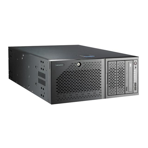
Apcon ACI-3144-XR User manual

A54-3144-XR • Rev BAPCON, Inc. • www.apcon.com • +1 503-682-4050 • 800-624-6808
INTELLAFLEX XR Switch
ACI-3144-XR Chassis User Manual
• Four-blade chassis • Up to 144 ports • 4 RU
• Embedded command line and graphical user interfaces
• Advanced network monitoring features:
• Packet aggregation with multi-stage filtering, data rate
conversion, load balancing, and more
• Multi-function and other advanced features

February 2016
Copyright ©2016 by APCON, Inc.
All rights reserved.
This manual is copyrighted. No part of this manual may be reproduced, transmitted, copied, or translated in any form or by
any means, electronic or mechanical, including photocopying and recording, for any purpose without the express written
permission of APCON, Inc.
The hardware and software described in this document is furnished under a license agreement or nondisclosure agreement.
The hardware and software may be used or copied only in accordance with the terms of the agreement. It is against the law
to copy the software on any medium except as specifically allowed in the license or nondisclosure agreement.
APCON, Inc. reserves the right to revise this publication from time to time without obligation of APCON to notify any person or
organization of such revision. APCON has prepared this manual for use by customers as a guide for proper installation,
operation and maintenance of APCON equipment. The drawings, specifications and information contained within this
document are the property of APCON, and any unauthorized use or disclosure of the enclosed information is prohibited.
APCON, INTELLAPATCH, INTELLAPORT, INTELLASCAN, INTELLASTORE, and INTELLATAP are registered trademarks of APCON, Inc.
All other trademarks, registered trademarks, service marks, and trade names are the property of their respective owners.
APCON is an Equal Opportunity Employer—M/F/D/V.APCON is an Equal Opportunity Employer—M/F/D/V.
A54-3144-XR • Rev B 2 APCON, Inc.

A54-3144-XR • Rev B 3 APCON, Inc.
Chapter 1: Preface
What you need to know.......................................................................................................................... 7
About this manual................................................................................................................................... 7
Contents of this manual ................................................................................................................. 7
Conventions for notification ........................................................................................................... 8
Conventions for the user interface ................................................................................................ 8
APCON software products ...................................................................................................................... 9
Applications and web browsers supported........................................................................................... 9
Contact APCON .....................................................................................................................................10
Chapter 2: Introducing the chassis
Overview ................................................................................................................................................11
Features ................................................................................................................................................13
Modular hardware ........................................................................................................................13
Embedded software ......................................................................................................................14
About the ACI-3144-XR chassis...........................................................................................................15
Chapter 3: Specifications and compatibility
Physical specifications .........................................................................................................................17
Safety and compliance.........................................................................................................................18
Power and electrical specifications.....................................................................................................18
AC power specifications ...............................................................................................................19
AC Power Cords ......................................................................................................................19
DC power specifications ...............................................................................................................20
DC Power Cords .....................................................................................................................21
Dedicated circuit required .....................................................................................................22
Earthing for DC power supplies .............................................................................................22
Specifications for interfaces ................................................................................................................23
LAN ports .......................................................................................................................................23
Serial port ......................................................................................................................................23
RJ-45 cable pin-outs ..............................................................................................................24
DB-9 adapter pin-outs ...........................................................................................................24
SD card and USB port ...................................................................................................................25
Specialty interfaces ......................................................................................................................25
Status LEDs ...................................................................................................................................25
Front of the chassis ...............................................................................................................25
Back of the chassis ................................................................................................................25
Compatibility .........................................................................................................................................26
Blades supported ..........................................................................................................................26
Contents

APCON, Inc. 4 A54-3144-XR • Rev B
Contents ACI-3144-XR Chassis User Manual
SFP ports and transceivers supported ........................................................................................27
Characteristics of SFP+ and QSFP+ transceivers ................................................................27
Port numbering .............................................................................................................................28
Chassis defaults ...................................................................................................................................29
Chapter 4: Installation and set up
Plan the installation..............................................................................................................................31
Safety precautions ........................................................................................................................32
Rack mount preparation ..............................................................................................................32
Mechanical loading ................................................................................................................32
Operating ambient temperature ..........................................................................................32
Air flow ....................................................................................................................................32
Protect sensitive equipment ........................................................................................................32
Unpack the carton ................................................................................................................................33
Install the chassis.................................................................................................................................34
Rack installation ...........................................................................................................................34
Table top installation ....................................................................................................................34
Install blades and transceivers ....................................................................................................35
Connect power to the chassis..............................................................................................................35
Connect AC power .........................................................................................................................35
Connect DC Power ........................................................................................................................36
Connect the chassis .....................................................................................................................38
Next steps .............................................................................................................................................38
Chapter 5: Configure the chassis
Default settings.....................................................................................................................................39
Use the front panel interface...............................................................................................................40
Control buttons .............................................................................................................................40
Home Screen .................................................................................................................................41
Main Menu ....................................................................................................................................41
Status Menu ..................................................................................................................................42
Status > System Status .........................................................................................................42
Status > Failover Status ........................................................................................................43
Status > Online Users ............................................................................................................44
Configuration .................................................................................................................................45
Configuration > Audible Alarms ............................................................................................46
Configuration > IPv4 Config ..................................................................................................46
Configuration > IPv6 Config ..................................................................................................50
Configuration > Telnet ...........................................................................................................53
Configuration > SSH ..............................................................................................................54
Configuration > Restart Services ..........................................................................................54
Configuration > Factory Reset ..............................................................................................55
Configuration > Wipe .............................................................................................................55
Failover ..........................................................................................................................................56
Failover > Status .....................................................................................................................57
Failover > Failover NOW... .....................................................................................................57
About ..............................................................................................................................................58
Use WEBXR to configure the switch .....................................................................................................59
Before you begin using WEBXR .....................................................................................................59

A54-3144-XR • Rev B 5 APCON, Inc.
ACI-3144-XR Chassis User Manual Contents
Steps to configure using WEBXR ..................................................................................................59
Name the chassis (optional) ........................................................................................................62
Use CLI to configure the chassis .........................................................................................................64
Before you begin using CLI ...........................................................................................................64
Steps to configure using CLI ........................................................................................................64
Chapter 6: Maintain the chassis
Maintenance of components...............................................................................................................68
Hot-swappable modules ...............................................................................................................68
Replacement of controller battery ...............................................................................................68
Blades....................................................................................................................................................69
Transceivers and fiber optic cables.....................................................................................................70
Safety precautions ........................................................................................................................70
Cleaning tools ................................................................................................................................71
Care of fiber optic cables ......................................................................................................71
Install and remove transceivers ..................................................................................................73
Clean transceiver modules ....................................................................................................74
Power supplies......................................................................................................................................74
Fan module ...........................................................................................................................................75
Controllers.............................................................................................................................................76
System recovery....................................................................................................................................77
Before you begin ...........................................................................................................................78
Prepare for the procedure .....................................................................................................78
Remove the Secondary Controller ........................................................................................78
Power down the chassis ........................................................................................................80
Reset the Primary Controller ........................................................................................................80
Reset the Secondary Controller ...................................................................................................81
Log into WEBXR and restore settings ...........................................................................................82
Software updates .................................................................................................................................82
Index ............................................................................................................................................85

APCON, Inc. 6 A54-3144-XR • Rev B
Contents ACI-3144-XR Chassis User Manual

A54-3144-XR • Rev B 7 APCON, Inc.
Chapter 1: Preface
This manual describes the ACI-3144-XR chassis in the APCON
®
family of
INTELLAFLEX
XR chassis.
What you need to know
This manual provides information for those who install, use, and maintain the
ACI-3144-XR chassis. This manual assumes that you know how to:
• Evaluate your environment for power and temperature requirements
• Set up and configure electronic equipment
• Connect systems to networks
About this manual
This section describes the contents and conventions used in this manual to display
commands, the user interface, or for notifications that need your attention.
Contents of this manual
Information provided in this manual includes product specifications, as well as how to
install, configure, and maintain the ACI-3144-XR chassis.
Chapter 1
Preface Chapter 1
NOTE
In this manual, the ACI-3072-XR chassis is used to illustrate examples throughout.
The instructions to install, connect, and remove or replace components involve the
same steps for any other INTELLAFLEX XR chassis.
Chapter Description
Chapter 1, Preface Describes naming conventions, related software
products, and contact information.
Chapter 2, Introducing
the chassis
Provides information about features and functionality of
the chassis.
Chapter 3,
Specifications and
compatibility
Provides specifications for the ACI-3144-XR chassis and
lists compatibility with various APCON blades. Also
describes pin-outs for connectors.
Chapter 4, Installation
and set up
Provides installation and configuration details.

APCON, Inc. 8 A54-3144-XR • Rev B
Chapter 1. Preface ACI-3144-XR Chassis User Manual
Conventions for notification
The conventions for notifications used in this manual are as follows. For color indicators,
icons, and symbols used in the WEBXR interface, refer to the WEBXR User Manual.
Any conventions specific to the ACI-3144-XR chassis are described in the chapters that
follow.
Conventions for the user interface
This manual uses the following text conventions:
Chapter 5, Configure
the chassis
Details the screens and options available to configure
the chassis, and provides detailed instructions to use the
LCD on the front panel of the chassis.
Chapter 6, Maintain
the chassis
Explains how to remove and reinstall blades,
transceivers, power supplies, the Fan Module, and
controllers. Also discusses software updates.
Chapter Description (continued)
Icon Label Description
(None) Note Indicates important or supplemental information about the
product or a feature.
Caution Indicates potentially hazardous situations or unsafe
practices which, if not avoided, may result in minor or
moderate injury or damage to data or hardware.
ESD Caution Indicates situations that may cause damage to hardware via
Electrostatic Discharge (ESD).
Electrical
Grounding
Requires that you always discharge any static electricity on
your body by touching a grounded bare metal surface or an
approved anti-static mat before picking up an ESD-sensitive
electronic component.
Convention Description
In WEBXR, click the icon for the soft arrow on a menu bar, window,
dialog box, and so on to display options such as menus, dialog
boxes, or pop-up windows.
When instructions refer to “click the soft arrow”, you can alternately
right-click on an icon, blade, or port to display options.
Using either method, different options or menus may be displayed
depending on the area in which the soft arrow or right-click is
selected. For example, clicking in the open area of a blade versus
the open area of a port displays different menu options.
>Movement through menu options. For example, a sequence to view
the Ports page is displayed as “Global View > Ports”.
MonoText
Information displayed on the page.
ItalicText
Variable parameters.
Button A button in WEBXR that you click to perform a function.

A54-3144-XR • Rev B 9 APCON, Inc.
ACI-3144-XR Chassis User Manual Chapter 1. Preface
APCON software products
APCON provides the following software products to access, control, and monitor your
INTELLAFLEX XR chassis:
•WEBXR, embedded in an XR chassis, lets you control a switch remotely from a web
browser over a network or the Internet. For security, you can enable SSL. For more
information, see the WEBXR User Manual.
•CLI, embedded in an XR chassis, provides an interactive Telnet, SSH, and serial
console command line interface. See the CLI Reference Manual for XR Chassis.
•NETVIS, embedded in the chassis (but purchased separately), provides a more intuitive
way to connect SPAN or monitor ports to network tools. For more information, see the
NETVIS User Manual).
•SNMP provides programmatic access to the chassis and is used primarily for SNMP
management applications. (SNMPv3 is included with the software.) For more
information, see the APCON Support Site (http://support.apcon.com).
•TITANXR, purchased separately, is a web-accessible centralized point of control to
monitor switches, notify designated users of alert conditions, analyze network traffic
using RMON statistics, schedule and implement software upgrades in batch mode,
and manage user accounts. Using TITANXR, network traffic running across a KVM
hypervisor on a separate Linux server can be mirrored, filtered, and directed into a
unidirectional GRE tunnel (created by TITANXR) that is terminated on an INTELLASTORE II
for analysis. For more information, see the TITANXR User Manual.
•APCON MOBILE APP, available for Android tablets and smart phones, extends TITANXR
management by providing a global view and real-time status of the APCON monitoring
network. This allows technical staff to view and diagnose issues remotely at all times,
thus reducing the time to resolve issues. The user-friendly interface provides network
visibility, system and link status, alarm notifications, and log history.
For more information about each of these products, contact your APCON sales
representative (see page 10).
Applications and web browsers supported
Following are the applications and web browsers tested for INTELLAFLEX XR chassis:
• Adobe Flash Player (v18.0 or later). To download a current version, go to the Adobe
website.
• A web browser such as the ones listed below (other browsers may also work). The
versions of Internet browsers tested for this release include:
• Google Chrome v43.x
• Mozilla Firefox v38.0.5
• Microsoft Internet Explorer v11.x (64-bit edition)

APCON, Inc. 10 A54-3144-XR • Rev B
Chapter 1. Preface ACI-3144-XR Chassis User Manual
Contact APCON
To request technical assistance:
•On the Web: APCON maintains an active website that containing current information
about the company and sales office locations, new and existing products, sales
contacts, service, documentation, and technical support information.
• APCON main website: https://www.apcon.com
• APCON Support site: https://support.apcon.com
•By phone:
• If you purchased your product from APCON, contact your sales representative
directly.
• APCON, Inc. standard technical support is available by phone as follows:
• By e-mail:
•Bymail:
APCON, Inc.
Attn: Customer Support
9255 SW Pioneer Court
Wilsonville, OR 97070 USA
1–503–682–4050 Monday—Friday, 8AM—5PM (U.S. Pacific Time)
1–503–682–4059 24×7×365 FAX
1–800–571–4793 24×7×365 for Premium Global Service Members –
US Domestic
1–503–682–4050,
Option 5
24×7×365 for Premium Global Service Members –
International
NOTE
When sending e-mail to technical support, remember to include configuration
information about your current hardware and software.

A54-3144-XR • Rev B 11 APCON, Inc.
Chapter 2: Introducing the chassis
Overview
The APCON
®
family of
INTELLAFLEX XR chassis provide network visibility to monitoring and
security tools, maximizing uptime for a range of business environments.
When populated with INTELLAFLEX blades, these chassis allows you to aggregate, filter, and
direct data to network monitoring and analysis equipment. In addition, specialty blades
offer features such as data capture and storage, Bypass mode, and Multi-Function
features such as time-stamping, packet-slicing, deduplication, and protocol stripping.
Chapter 2
Introducing the chassis Chapter 2
Overview 11
About the ACI-3144-XR chassis 15
Features 13

APCON, Inc. 12 A54-3144-XR • Rev B
Chapter 2. Introducing the chassis ACI-3144-XR Chassis User Manual
These INTELLAFLEX XR chassis offer scalability for every business need:
INTELLAFLEX XR chassis deliver up to 2.88 Terabits per second of data throughput (360
Gbps per blade). You can monitor up to 288 non-blocking 10 Gbps Ethernet ports in an
8 RU chassis.
Embedded software provides two-click connections using a browser-based interface. The
chassis supports full command line and SNMP interfaces, as well as a front panel that you
can use to quickly configure the chassis.
The ACI-3144-XR chassis work with legacy 1G analysis tools, preserving your investment
and reducing the overall cost of ownership.
The advanced design of INTELLAFLEX XR chassis are ideally suited for trunking multiple
switches together. This design enables unified monitoring for even the largest data
centers.
Chassis Description
ACI-3288-XR 8 blades, up to 288 ports total in an 8 RU chassis
ACI-3144-XR 4 blades, up to 144 ports total in a 4 RU chassis
ACI-3072-XR 2 blades, up to 72 ports total in a 2 RU chassis
ACI-3036-XR 1 blade, up to 36 ports total in a 1 RU chassis

A54-3144-XR • Rev B 13 APCON, Inc.
ACI-3144-XR Chassis User Manual Chapter 2. Introducing the chassis
Features
The modular chassis design offers the following features across all INTELLAFLEX XR models
to simplify operations management:
• Patented aggregation and filtering technology
• Packet-switched architecture for simultaneous non-blocking connectivity
• Support for 1G, 10G, and 40G Ethernet
• Architecture designed for 100G migration
• Front panel LCD touch screen to easily configure the chassis at time of set-up
The following example shows the front view of an ACI-3072-XR chassis with two blades
installed. The touch-screen panel is on the left on all INTELLAFLEX XR chassis, and LEDs on
the right of each blade displays the state of operational readiness and power.
All INTELLAFLEX XR chassis are designed for standard 19-inch racks. Depending on the
weight to be supported, chassis can also be set on a stable flat surface, such as a table in
a clean environment. For more details, see Physical specifications on page 17.
Modular hardware
The ACI-3144-XR uses modular hardware to ensure high availability as well as ease of
maintenance. Hot-swappable, replaceable components are compatible across all
INTELLAFLEX XR chassis, and include:
• Controllers
• Power supplies (AC or DC)
•Blades(seeBlades supported on page 26)
• Transceivers
Two LAN ports and one serial port are provided on each controller for remote software
management.
Front LCD
panel
Blade status and
power LEDs
Blade
thumbscrews

APCON, Inc. 14 A54-3144-XR • Rev B
Chapter 2. Introducing the chassis ACI-3144-XR Chassis User Manual
The following illustration shows an ACI-3072-XR chassis as an example of the back view of
a chassis. Each chassis is equipped with power supplies (either AC or DC), controllers, and
the Fan Module. Views of other chassis models are shown in the next section.
Separate data and control plane architecture maintains connections during controller
swaps. You can easily remove and replace power supplies and the Fan Module.
For redundancy, fully populate the chassis with the maximum number of power supplies.
This can prevent loss of service in the event of a single power supply failure. The number
of power supplies and controllers depends on the model of the chassis, as shown in the
following table:
For more information about power supplies, see Power and electrical specifications on
page 18.
Embedded software
In addition to the hardware-specific features, APCON embedded software offers the
following common software in all INTELLAFLEX XR chassis:
• Advanced web-based graphical user interface (WEBXR) to use a point-and-click
interface to create connections/aggregations and manage the system
• CLI interface, a command-line interface with serial, Telnet, and SSH support
• Embedded SNMP, a programmatic interface used primarily for automated scripts
and SNMP management applications.
Use these software interfaces to perform the following tasks, as well as many others:
• Create connections between ports and view port status
• Monitor system status
• Configure the serial and LAN ports
• Set blade and port data rate
• Run multi-user sessions
• Configure services and security
INTELLAFLEX XR
Chassis
Power Supply Controller
Ships with Maximum Standard Maximum
ACI-3144-XR 2412
Removable
power supplies
LAN ports Removable
Fan Module
Removable
controllers
Serial port

A54-3144-XR • Rev B 15 APCON, Inc.
ACI-3144-XR Chassis User Manual Chapter 2. Introducing the chassis
The ACI-3144-XR’s internal non-volatile memory retains configuration and set-up
information such as port settings and control parameters. See the WEBXR User Manual for
details.
About the ACI-3144-XR chassis
The ACI-3144-XR chassis contains:
• Up to four (4) high-density blades in INTELLAFLEX XR chassis
• Up to 36 ports on each blade (a maximum of 360 Gbps throughput per blade),
with a total of 144 ports available (maximum of 1.44 Tbps throughput)
The following illustration shows a front view of an ACI-3144-XR fully populated with APCON
INTELLAFLEX blades. Your chassis may have a different appearance if equipped with
different blades.
The next illustration shows a back view of an ACI-3144-XR chassis.

APCON, Inc. 16 A54-3144-XR • Rev B
Chapter 2. Introducing the chassis ACI-3144-XR Chassis User Manual

A54-3144-XR • Rev B 17 APCON, Inc.
Chapter 3: Specifications and compatibility
This chapter describes the specifications for an APCON
®
an INTELLAFLEX XR chassis.
Physical specifications
This section describes the physical specifications for the ACI-3144-XR chassis.
Size:
Weight:
Operating environment:
Chapter 3
Specifications and compatibility Chapter 3
Physical specifications 17
Safety and compliance 18
Power and electrical specifications 18
Specifications for interfaces 23
Compatibility 26
Chassis defaults 29
Chassis Dimensions RU
ACI-3144-XR 7.0 x 17.2 x 25.0 inches (17.8 x 43.7 x 63.5 cm) 4 RU
Chassis Weight
ACI-3144-XR 46.0 lb./20.9 kg (fully loaded with 4 36-port blades and SFPs)
Item Description
Ambient temperature for the
operating environment
32°F to 122°F (0°C to 50°C)
Storage temperature –40°F to 158°F (–40°C to 70°C)
Relative Humidity Operating: 10% to 85% (non-condensing)
Storage: 0% to 95% (non-condensing)
Temperature alarm 80° Celsius (default; can be changed)

APCON, Inc. 18 A54-3144-XR • Rev B
Chapter 3. Specifications and compatibility ACI-3144-XR Chassis User Manual
Safety and compliance
Following are the safety and compliance specifications for an INTELLAFLEX XR chassis:
Power and electrical specifications
Customers must provide the source of power on site. Verify that there is enough power
available to support all units that you plan to install in the rack.
The ACI-3144-XR chassis operates with the following specifications for power
requirements and consumption. These specifications assume that no blades are installed
in the chassis.
Consider the effect that connecting equipment to the supply circuit might have on
overcurrent protection and supply wiring. Use the nameplate ratings on all equipment
when addressing this issue.
For details about specifications for AC and DC power supplies, see the following sections.
•ACpower(AC power specifications on page 19)
•DCpower(DC power specifications on page 20)
For an INTELLAFLEX XR chassis, a power supply can fail without affecting chassis operation.
Use the WEBXR interface to specify which power supplies cause audible alarms when a
power supply fails or is powered down.
To provide redundant power to the chassis in case of a failure in one power supply, the
chassis must be fully populated with the maximum number of power supplies, as shown in
the following table:
For example, if a chassis has multiple power supplies installed and one power supply fails,
the load is distributed across the remaining power supplies.
Item Description
Safety UL 60950, IEC/EN 60950, CSA C22.2 60950
EMC EN 55022, EN61000, FCC Part 15, ICES 003
Compliance UL, CE-Mark, RoHS compliant, OSHA, 29 CFR Part 1910
Chassis Power/Watts Power/BTU
ACI-3144-XR 250 Watts 853 BTU
NOTE
Specifications for blade power ranges from 150—320 Watts (512–1092 BTU) per
blade installed in the chassis.
Chassis Available Slots Minimum Shipped For Redundancy
ACI-3144-XR 424

A54-3144-XR • Rev B 19 APCON, Inc.
ACI-3144-XR Chassis User Manual Chapter 3. Specifications and compatibility
AC power specifications
Following are the power specifications for the AC power supply in the ACI-3144-XR chassis:
To verify the operational status of the power supply, see page 36.
AC Power Cords
Unless otherwise specified, each ACI-3144-XR chassis ships with one power cord for each
AC power supply. Each power cord features IEC-C13 socket power as the female end to
connect with an INTELLAFLEX XR chassis.
APCON offers a complete selection of power cords and adapters with different voltages
and plug ends to meet electrical requirements in countries around the world, as shown in
the following table:
Power Supply Description
AC power supply
(P/N ACI-3100-AC)
•100-240 volt AC, auto-sensing 50–60 Hz
• Maximum 1080 Watts
Power Cord APCON P/N Type/Voltage Primarily used in
A50-0080-120 Type B, American
3-pin Grounded
100—127 V
USA
Canada
Mexico
Central America
Japan
ACI-0080-625 Type C
European 2-pin
220—240 V
All countries of
Europe except the
United Kingdom,
Ireland, Cyprus and
Malta; some Asia
ACI-0080-650 Type G, European
3-pin Grounded
220—240 V
United Kingdom
Ireland
Malta, Malaysia
Singapore

APCON, Inc. 20 A54-3144-XR • Rev B
Chapter 3. Specifications and compatibility ACI-3144-XR Chassis User Manual
A power cord for South Africa is also available (ACI-0080-550). Contact your sales
representative for more information.
DC power specifications
Following are the power specifications for the DC power supply in the ACI-3144-XR
chassis:
ACI-0080-525 Type I
Australian 3-pin
Grounded
220—240 V
Australia
New Zealand
China
Argentina
ACI-0080-425 Power Extension
Cord for rack
power distribution
250 V
Canada /
Japan /
Others
Power Cord APCON P/N Type/Voltage Primarily used in
Power Supply Description
DC power supply
(P/N ACI-3100-DC)
• DC power: —48 DC (–40 to –72 VDC)
• Maximum 1080 Watts
IMPORTANT
You must dedicate a 30 Amp circuit for each installed DC power supply.
Table of contents
Popular Chassis manuals by other brands

National Instruments
National Instruments VXI Series user manual

CommScope
CommScope Quareo HDEP Series user manual

Philips
Philips EJ3.0UPA Service manual

Overland Storage
Overland Storage SnapServerXSR 40 Replacement instructions

Streacom
Streacom FC5 evo user guide

Sencore
Sencore AG 4800XS quick start guide