List of Figures
x Intel®Server Chassis P4000S Service Guide
List of Figures
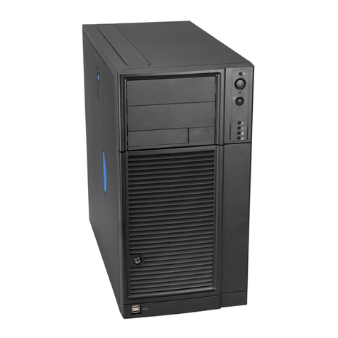
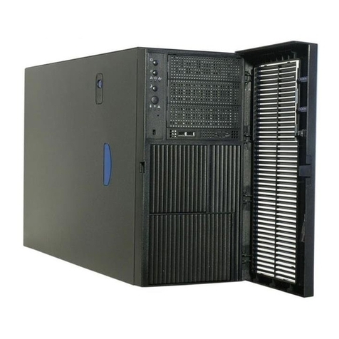
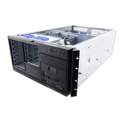
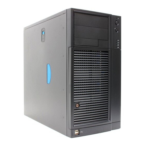
Figure 1. Chassis Front View for Fixed Hard Drive Configuration................................................1
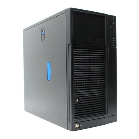
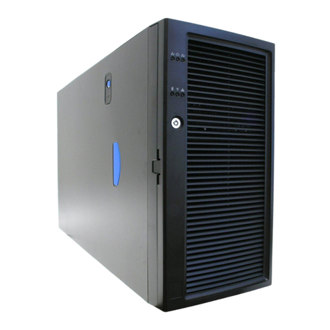
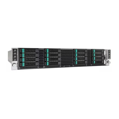
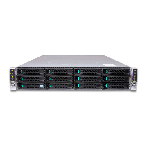
Figure 2. Chassis Front View for Hot-swap Hard Drive Configuration .........................................1
Figure 3. Internal Chassis View of Intel®Server Chassis P4304XXSFCN ...................................3
Figure 4. Internal Chassis View of Intel®Server Chassis P4304XXSHCN...................................4
Figure 5. Internal Chassis View of Intel®Server Chassis P4304XXSFEN....................................5
Figure 6. Internal Chassis View of Intel®Server Chassis P4304XXSHEN...................................6
Figure 7. Internal Chassis View of Intel®Server Chassis P4304XXSFDR ...................................7
Figure 8. Internal Chassis View of Intel®Server Chassis P4304XXSHDR...................................8
Figure 9. Front Panel Controls and Indicators.............................................................................9
Figure 10. Back Panel Layout (with Fixed Power Supply) .........................................................10
Figure 11. Back Panel Layout (with Hot-swap Power Supply)...................................................11
Figure 12. 4x3.5'' HSBP Board (Rear View)..............................................................................12
Figure 13. 4x3.5'' HSBP Board Layout (Front View)..................................................................12
Figure 14. Removing the Chassis Cover...................................................................................14
Figure 15. Installing the Chassis Cover.....................................................................................15
Figure 16. Removing the Front Bezel........................................................................................16
Figure 17. Installing the Front Bezel..........................................................................................16
Figure 18. Removing DVD or CD-ROM Drive ...........................................................................17
Figure 19. Re-inserting Empty EMI Shield.................................................................................17
Figure 20. Removing EMI Shield...............................................................................................18
Figure 21. Installing DVD or CD-ROM Drive .............................................................................18
Figure 22. Removing the EMI Shield.........................................................................................19
Figure 23. Installing the EMI Shield...........................................................................................19
Figure 24. Removing Fixed Hard Drives....................................................................................20
Figure 25. Removing the 3.5'' HDD from Fixed HDD tray..........................................................20
Figure 26. Removing the 2.5'' HDD from Fixed HDD tray..........................................................21
Figure 27. Reinstalling the HDD Carrier Tray............................................................................21
Figure 28. Removing Fixed Hard Drive .....................................................................................22
Figure 29. Securing the 3.5'' HDD on Fixed HDD Carrier Tray..................................................22
Figure 30. Securing the 2.5'' HDD on Fixed HDD Carrier Tray..................................................23
Figure 31. Inserting the HDD Carrier Tray.................................................................................23
Figure 32. Removing the 4x3.5'' HDD Cage..............................................................................24
Figure 33. Removing the EMI shield .........................................................................................25
Figure 34. Installing the EMI shield ...........................................................................................26
Figure 35. Installing the 4x3.5'' Hot-Swap Hard Drive Cage......................................................26
Figure 36. 4x3.5'' Hot Swap Backplane Cable Connections......................................................27
Figure 37. Removing 4x3.5'' Hot-swap Backplane ....................................................................28
Figure 38. Installing 4x3.5” Hot-swap Backplane.......................................................................28
Figure 39. Removing the 2.5" HDD interface bracket from Carrier............................................29
Figure 40. Installing the 3.5" HDD into the Carrier.....................................................................30
Figure 41. Removing the 2.5" HDD interface bracket from Carrier............................................30
Figure 42. Breaking off the tab on the bracket...........................................................................31
Figure 43. Installing 2.5" HDD interface bracket into Carrier .....................................................31
Figure 44. Installing the 2.5" HDD into carrier ...........................................................................32
Figure 45. Installing the Airduct.................................................................................................33
Figure 46. Removing the Airduct...............................................................................................33
Figure 47. Removing Fixed Power Supply ................................................................................34
