IR/TRACCFACC
MOPRVCLFWCL
MAXOFS2OFS1
10A
5A
2.5A
1.7A
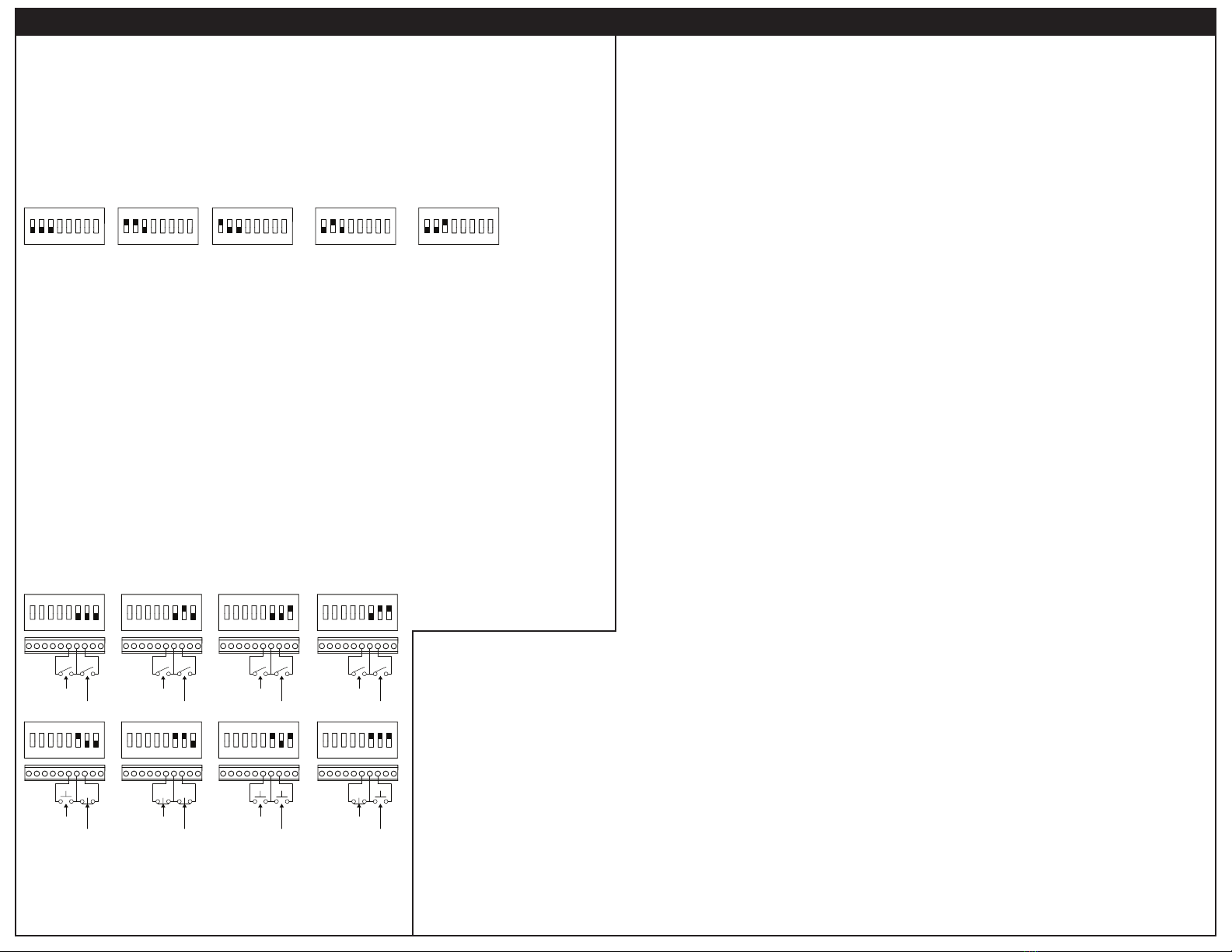
Place the jumper on 10A if using a motor between 5 and 10 amps.
Place the jumper on 5 A if using a motor between 2.5 and 5 amps.
Place the jumper on 2.5A if using a motor between 1.7 and 2.5 amps.
Place the jumper on 1.7A if using a motor smaller than 1.7 amps.
MOTOR CURRENT
SELECT
FEEDBACK
SELECT
A180
A90
TACH
J504
Place the jumper on A180 if using a 180 VDC motor with no tach feedback.
Place the jumper on A90 if using a 90 VDC motor with no tach feedback.
Place the jumer on TACH if using tach feedback.
Feedback Select
If using tachogenerator feedback, set the feedback select jumper for TACH. If no tachogenerator
feedback is used, set the feedback select jumper to A90 if using a 90 VDC motor or to A180 if using a
180 VDC motor.
Motor Current Select
of the motor. This adjusts the scaling of the current limit trim pots to allow for as small a range on the
POWER JUMPERS
Setup
US
10A
5A
2.5A
1.7A
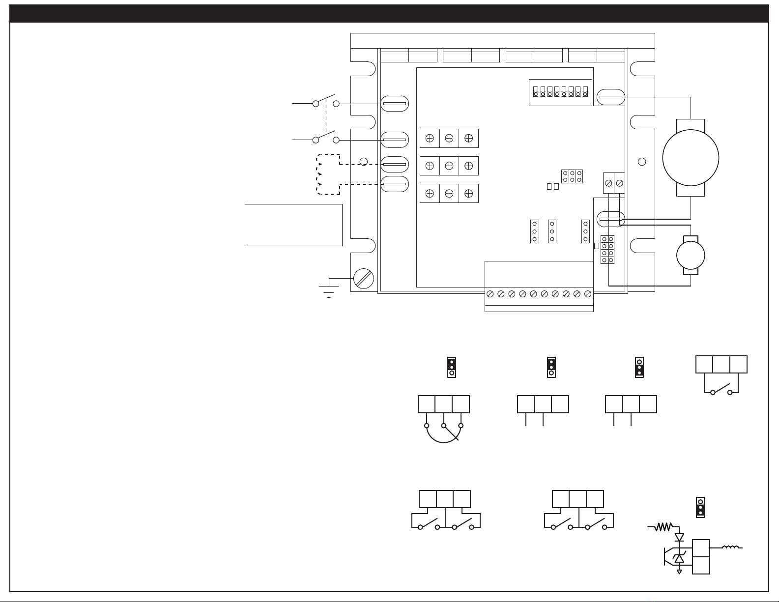
A2 A1
F- F+
L2L1
COM SIG1 10V SIG2 DIR EN COM INH COM AUX
OUT IN
SIG2SIG1
VDC
mA
T1 T2
A180
A90
TACH
J504
STAT
LIMIT
OFFSET1 FACC FWDCL MAXSPD
OFFSET2 RACC REVCL IRCOMP
1 2 3 4 5 6 7 8
ON
STATUS LED
BOTTOM BOARD
LIMIT LED
TOP BOARD
STAT LED
TOP BOARD
Status 1 LED (STAT): Green LED on Top Board
1 FLASH: The drive is disabled. Refer to DIP Switches 6 and 7 and terminal EN.
2 FLASHES: Cycle the AC power, enable, or inhibit.
2 FLASHES: Refer to DIP Switch 4.
5 OR MORE FLASHES: Contact the factory.
Limit LED (LIMIT): Red LED on Top Board
SOLID: The drive is in current limit. The motor is asking for more current than what the drive
SOLID: is set for. Refer to FWDCL and REVCL trim pots.
1 FLASH: The power board is not receiving a run command from the top board.
2 OR MORE FLASHES: Contact the factory.
LEDs
MGC403 series drives are suitable for use on a circuit capable of
•
• board. Hold the drive by the chassis only.
• Protect the drive from dirt, moisture, and accidental contact.
• temperature range.
•
• chassis to the subplate.
• The chassis should be earth grounded. Connect the ground to the green screw on the chassis.
60°
wiring.
to shield power conductors, it is recommended to shield all logic-level leads. If shielding of logic-level
Installation
ALL DIMENSIONS IN INCHES [MILLIMETERS]
US
10A
5A
2.5A
1.7A
A2 A1
F- F+
L2L1
COM SIG1 10V SIG2 DIR EN COM INH COM AUX
OUT IN
SIG2SIG1
VDC
mA
T1 T2
A180
A90
TACH
J504
STAT
LIMIT
1 2 3 4 5 6 7 8
ON
3.64 [93]
3.00 [76]
1.25 [32]
0.50 [13]
3.80 [97]
4.30 [110]
1.34 [34]
0.95 [24]
1.94 [50]
Dimensions
• Have a
•
•Electrical Code and all other applicable electrical and safety codes, including the provisions of the
•
• . Avoid direct contact with the printed
•circuit board or with circuit elements to prevent the risk of serious injury or fatality. Use a non-
•
•equipment and insulated tools if working on this drive with power applied.
•
• The
•switch contacts should be rated for 250 VAC and 200% of motor nameplate current.
• Do not use
•
•
•method for emergency stopping.
•
•
•produce high torque. This may cause damage to motors.
• unless power is removed or the drive is
•disabled. Opening any one lead while the drive is running may destroy the drive.
•using a permanent magnet motor.
• Under no circumstances should power and logic level wires be bundled together.
•input will cause damage to the drive.
•
•
•in accordance with NEC standards.
READ ALL SAFETY WARNINGS BEFORE INSTALLING THIS EQUIPMENT
Safety Warnings
......................................................115/230 VAC ± 10%, 50/60 Hz, single phase
........................................................................................................0 - 15 Amps
..............................................................50 or 100 VDC
............................................................100 or 200 VDC
...................................................................................................0.74 Amps
...................................................................................................1.37 at base speed
..........................................................1% base speed
.............................................0.1% base speed
................................................................................50:1
......................................................................60:1
....................................................................................0.5 - 15 seconds
..................................................................................0.5 - 15 seconds
.........................................................................................................................3 kV
...........0 to ± 10 VDC; 4 - 20 mA
..................................................................>100K ohms
.......................................................................10°C - 50°C
...............................................cULus Listed, UL 61800-5-1, File # E132235
AC Line Voltae
AC Line Current
with 115 VAC line voltage
with 230 VAC line voltage
Maximum Field Current
Form Factor
with Armature Feedback
with Tachogenerator Feedback
with Armature Feedback
with Tachogenerator Feedback
Input Impedance (COM to SIG1 / SIG2)
(0 - 50 Hz)
(>50 Hz)
* Heat sink kit 223-0159 must be used when the output is over 8 amps.
1/50 - 1/8
1/25 - 1/4
1/8 - 1
1/4 - 2
1.5
11.0*
0 - 90
0 - 180
0 - 90
0 - 180
115
230
115
230
MGC403-1.5
MGC403-11
Armature
Horsepower
Range
Connuous
Armature
Current (Amps)
Armature
Voltage Range
(VDC)
Line
Voltage
(VAC)
Model
Specifications
Full manual available online
14300 De La Tour Drive
South Beloit, IL 61080
Phone: (800) AMCNTRL
(800) 262-6875
www.americancontrolelectronics.com
4Q SCR Chassis Microprocessor-based
Adjustable Speed Drive with Isolation
and Speed or Torque Modes
for PMDC or Field Wound Brushed Motors
MGC403
An ISO 9001:2008 Certified Company
TM