T25 Tube Compressor API Select
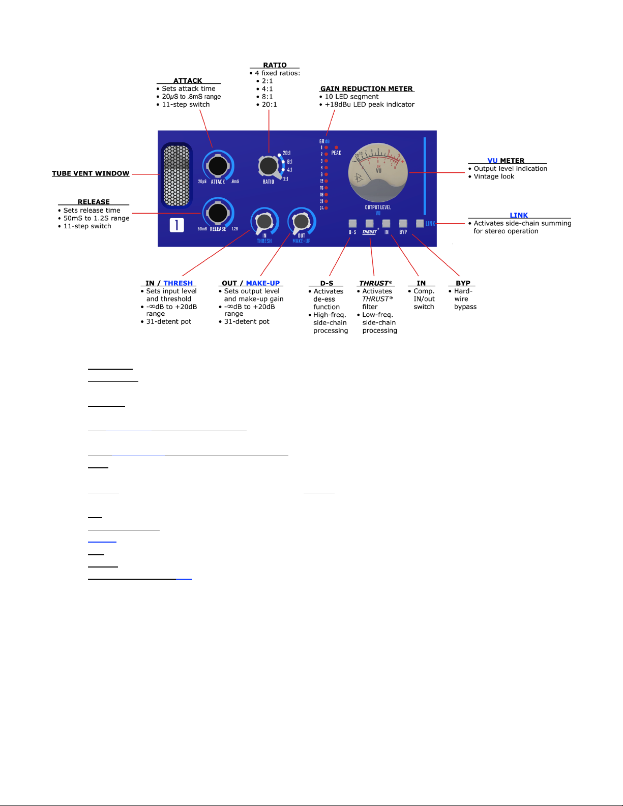
5.0 Side-Chain and Routing Controls
The T25 Tube Compressor is equipped with a flexible set of side-chain processes and routing controls.
Frequency-dependent side-chain processing includes a de-esser and the patented
THRUST
®filter that
helps you get more punch from audio with heavy low-frequency content. These features provide
increased control of the tonal characteristics and envelope shaping the compression applies to the
audio.
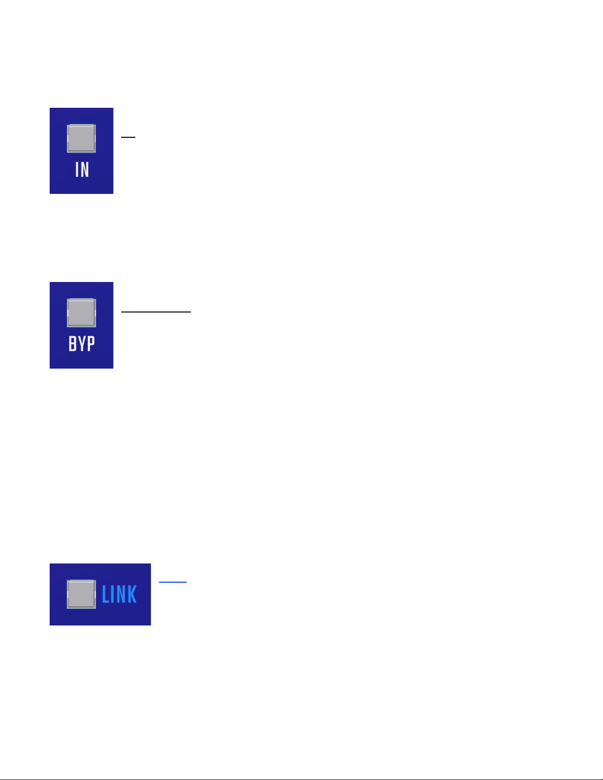
Routing options provide a compressor IN/out switch, hard-wire bypass, and linking for stereo
operation.
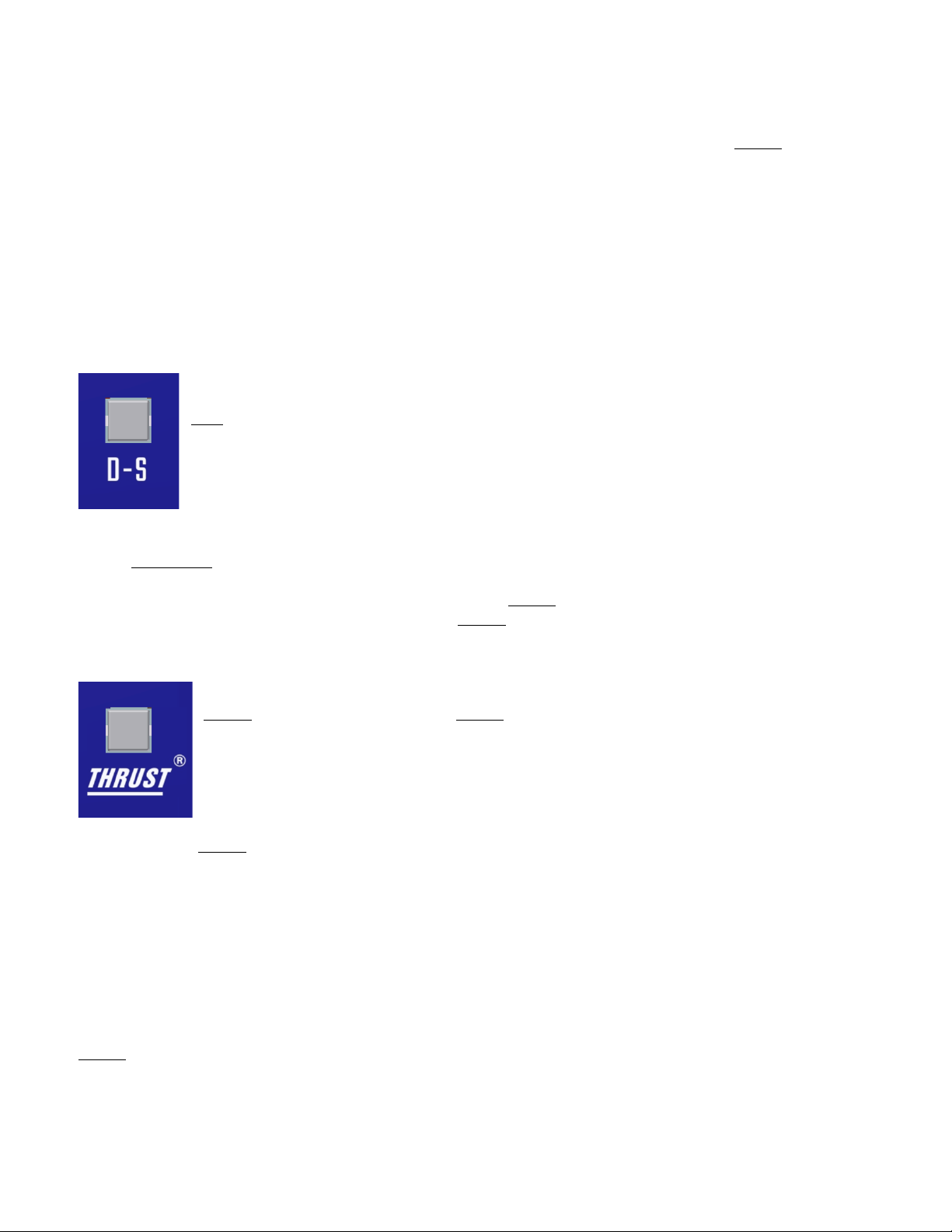
5.1 De-esser (D-S)
The D-S function provides a de-esser capability to the T25 for working with overly sibilant vocals.
D-S: Engage to activate the de-esser function
• Accentuates compression of high-frequency content
• Inserts a filter with 6kHz center before the RMS detector
• Illuminates when engaged
5.2
THRUST
®
The T25 Tube Compressor is equipped API’s patented
THRUST
®filter circuit that can be switched in or
out of the side-chain as needed. This places the
THRUST
®filter before the RMS detector that decreases
the compressor’s reaction to low frequency content. The result is a noticeable increase of punch and
low frequencies, but a uniformly compressed signal. It’s the “little more punch” switch!
THRUST
®:Engage to activate the
THRUST
®filter function
• Controls heavy low-frequency content in the detection path
• Inserts a 10dB/decade filter before the RMS detector
• Illuminates when engaged
The patented
THRUST
®circuit has been used for many years in the famed API 2500+ Stereo
Compressor, ATI Paragon and Paragon II consoles, as well as the Pro6 Input Strip. This circuit places
a filter in front of the RMS detector with a slope of 10dB per decade (-3dB/8va), which is the inverse
of the pink noise energy curve. In acoustics, the pink noise curve is used to equalize energy vs.
frequency over the audio spectrum, as sound requires more low frequency energy than high frequency
energy to sound correct to your ear. In Hi-fi equipment, a “LOUDNESS” contour is used to equalize
the music at lower levels so it sounds correct. Even with this curve, there is still a substantial amount
of low frequency information compared to high frequency information in the audio signal path. When
that signal is fed into the RMS detector, the detector will process the signal into a DC control voltage
based upon those louder low frequencies, resulting in a control voltage that favors the low frequencies
of the signal, causing pumping and a loss of punch. Sometimes, this is not desirable. By engaging the
THRUST
®switch, this inverse filter is placed in front of the RMS detector, evening out the energy by
lowering the energy in the low frequencies and increasing the energy in the high frequencies, so each
octave has the same energy instead of each octave having half the energy as the one lower. This
creates a unique compression effect that still reduces the overall gain, but the sound is much more
punchy and the signal actually sounds less compressed.