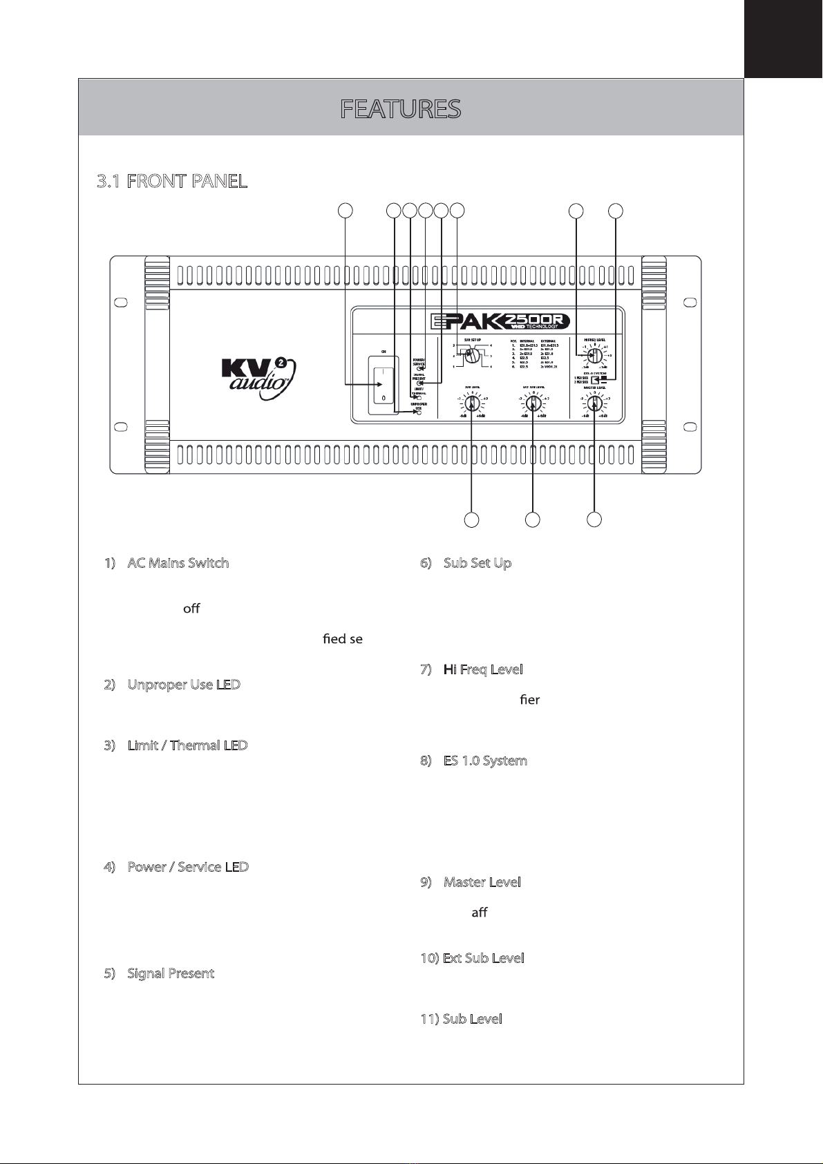
KV2 Audio EPAK2500R User manual

The future of sound.
Made perfectly clear.
At KV2 Audio our vision is to constantly develop
technologies that eliminate distortion and
loss of information providing a true dynamic
representation of the source.
Our aim is to create audio products that absorb
you, place you within the performance and deliver
a listening experience beyond expectation.
EPAK2500R
User Guide
ON
ES1.0 SYSTEM
0
-
6dB
-
3+3
+6dB
MASTER LEVEL
1 PER SIDE
2 PER SIDE
HI FREQ LEVEL
0
-
6dB
-
3+3
+6dB
SUB LEVEL
0
-
6dB
-
3+3
+6dB
EXT SUB LEVEL
POWER/
SERVICE
UNPROPER
USE
LIMIT/
THERMAL
SIGNAL
PRESENT
SUB SET UP
+1
0
-
1
-
3dB
-
2+2
+3dB
POS. INTERNAL EXTERNAL
1. ES1.8+ES1.5 ES1.8+ES1.5
2. 2x ES1.5 2x ES1.5
3. 2x ES1.8 2x ES1.8
4. ES2.5 ES2.5
5. ES2.5 2x ES1.8
6. ES2.5 2x VHD1.21
1
3
2
6
4
5
TECHNOLOGY
MID/HI
IN
PRE CONTROL
OUT
THROUGHT
SIGNAL OUT
INPUT
Z
MAIN
INPUT
INTERNAL
SUB IN
EXTERNAL
SUB IN
EXTERNAL
SUB OUT
50Ω
10 kΩ
TO ENSURE PROPER OPERATIONALLOW A MINIMUM OF 6 INS. CLEARANCE
FROM THIS SURFACEAND ADEQUATE VENTILATION. TO REDUCE THE RISK OF
ELECTRIC SHOCK. DO NOT REMOVETHIS PANEL OR ANY ATTACHED COMPONENT.
NO OPERATORSERVICEABLE PARTS INSIDE. REFER SERVICING TOQUALIFIED
PERSONNEL.TO REDUCE THE RISK OF FIRE OR ELECTRIC SHOCK, DO NOT EXPOSE
THIS APPLIANCE TO RAIN MOISTURE
AC IN
250 VAC
230 VAC
115 VAC
INTERNAL
SUB OUT
ES 1.0
TECHNOLOGY
115 VAC,50/60 Hz
MAX 2800WATTS
CAUTION
230 VAC,50/60 Hz
MAX 2800WATTS
HIGH VOLTAGE:DO NOT REMOVE THIS PANEL
CAUTION

IMPORTANT SAFETY INSTRUCTIONS
Before using your EPAK 2500R, be sure to carefully read the applicable items of these
operating instructions and the safety suggestions
1. Keep this manual for future reference.
2. Heed all warnings.
3. Follow all instructions.
4. Do not use this unit near water. Do not spill water or other liquids into or on the unit. Do not
operate the EPAK 2500R while wet or standing in liquid.
5. Clean only with dry cloth.
6. Do not block the air intake or exhaust ports. Install the unit in accordance with the
instructions.
7. Do not operate the EPAK 2500R near heat producing devices such as radiators, heat registers,
stoves or other apparatus that produce heat.
8. Always operate the unit with the chassis ground wire connected to the electrical safety earth.
Do not defeat the safety purpose of a grounding-type plug. A grounding type plug has two
pins and a third grounding prong. The third prong is provided for your safety. If the provided
plug does not t into your outlet, consult an electrician for replacement of the obsolete outlet.
9. Connect only to AC power outlets rated 115-250V, 50-60Hz.
10. Do not use this EPAK 2500R if the power cable is broken or frayed. Protect the power cable
from being walked upon or pinched particularly at the plugs and the point where it exits from
the apparatus.
11. Only use accessories specied by the manufacturer.
12. The unit is intended to be used in a 19” rack. Follow the mounting instructions. When a rack
on wheels is used, use caution when moving the loaded rack to avoid injury from tipping over.
13. Unplug this apparatus during lightning storms or when unused for long periods of time.
14. Do not connect an EPAK 2500R output in parallel or series with any other EPAK 2500R’s
output. Do not connect the EPAK 2500R output to any other voltage source, such as battery,
mains source, or power supply, regardless of whether the EPAK 2500R is turned on or o.
15. Do not run the output of any EPAK 2500R back into another channel's input.
16. Refer all servicing to qualied service personnel. Servicing is required when the apparatus has
been damaged in any way such as:
tPower-supply cord or plug is damaged
tLiquid has been spilled into the unit
tAn object has fallen into the unit
tThe unit has been exposed to rain or moisture
tThe unit does not operate normally
tThe unit was dropped or the enclosure is damaged
17. Do not remove top or bottom covers. Removal of the cover will expose hazardous voltages.
There are no serviceable parts inside and removal may void the warranty.
18. An experienced user shall always supervise this professional audio equipment, especially if
inexperienced adults or minors are using the equipment.
CAUTION: TO REDUCE THE RISK OF ELECTRIC SHOCK, DO NOT REMOVE THE COVER.
NO USER-SERVICEABLE PARTS INSIDE. REFER SERVICING TO QUALIFIED PERSONNEL.
WARNING: To prevent re or electric shock, do not expose this equipment to rain or moisture.

INDEX
1. Introduction
2. Getting Started
2.1 Unpacking
2.2 Rack Mounting
2.3 Cooling
2.4 AC Requirements
3. Features
3.1 Front panel
3.2 Rear panel
4.Using the System
4.1 Normal Set Up
4.2 Using the Mid/Hi Insert
4.3 Feeding the Subwoofers from another source
5.Specications
6. Block Diagram
7. Warranty Service & Contact Information

INTRODUCTION
Thank you for purchasing this KV2 Audio EPAK 2500R unit. This
manual contains important information on operating this unit correctly and safely.
Please take some time and read this manual to familiarise yourself with the advanced
features of this unit.
The EPAK 2500R is a four-way, active control and ampli ation system speci cally
designed for the KV2 Audio ES Series™ modular loudspeaker systems. It houses all
signal processing and as well as providing control for six t
subwoofer cabinet c ions, powered by the internal subwoofer ampli long
with providing control signal to an external VHD3200 subwoofer to power
further subwoofer cabinets if needed.
The ampli liment inside the EPAK 2500R is as follows:
High Frequency - 100-watt, Class AB, push pull, low intermodulation design.
Mid Frequency - 200-watt, Class AB, push pull, low intermodulation design.
Mid Bass - 600-watt, y, current-enhancing switch mode technology with
Linear Active Filter.
Subwoofer - 1600-watt, y, current-enhancing switch mode technology
with Linear Active Filter.
The EPAK 2500R is “Line Driver Ready” and has its own input impedance selector switch
on the rear panel to accurately match up the input impedance to the output of any
mixer used. In most cases it would be advisable to use a VHD LD4 line driver in addition
at the mixer end to ensure that the line to the ampli is driven correctly and the signal
integrity maintained.
Although this unit is simple to operate improper use can be dangerous. This is a very
high-powered device that can put out high voltages and sizeable currents. Always use
safe operating techniques with the EPAK 2500R.
FOR YOUR SAFETY, READ THE IMPORTANT PRECAUTIONS SECTION AS WELL AS
THE INPUT, OUTPUT AND POWER CONNECTION SECTIONS OF THIS MANUAL.
1

GETTING STARTED
2.1 UNPACKING
Unpack the EPAK 2500R and check to see if there is any damage to it. If you any
damage notify your supplier immediately. Only the consignee may institute a claim
with the carrier for damage incurred during shipping. Be sure to save the carton and
all packing materials for the carrier's inspection.
Should you ever need to ship the unit, only use the original factory packaging. If the
shipping carton is unavailable, contact your supplier to obtain a replacement.
The EPAK 2500R carton should contain:
tEPAK 2500R control unit
tUser's manual
tPowerCon detachable power cable
2.2 RACKMOUNTING
EPAK 2500R’s will mount in standard 19" rack systems. Integral rear mounting rack
ears are also provided for additional support, do not xing and mounting the
EPAK 2500R using just the front panel as support. Use eight screws and washers to
mount the ampli to the equipment rack rails (four for the front and four for the
rear). We recommend using a shock mounted rack for touring use to prolong the life
of your EPAK 2500R.
2
MID/HI
IN
PRE CONTROL
OUT
THROUGHT
SIGNAL OUT
INPUT
Z
MAIN
INPUT
INTERNAL
SUB IN
EXTERNAL
SUB IN
EXTERNAL
SUB OUT
50Ω
10 kΩ
TO ENSURE PROPER OPERATIONALLOW A MINIMUM OF 6 INS.CLEARANCE
FROMTHIS SURFACE AND ADEQUATEVENTILATION. TOREDUCE THE RISK OF
ELECTRIC SHOCK. DO NOTREMOVE THIS PANEL OR ANYATTACHED COMPONENT.
NO OPERATORSERVICEABLE PARTS INSIDE. REFER SERVICINGTO QUALIFIED
PERSONNEL.TO REDUCE THE RISK OF FIRE OR ELECTRIC SHOCK, DO NOT EXPOSE
THISAPPLIANCE TO RAIN MOISTURE
AC IN
250 VAC
230 VAC
115 VAC
INTERNAL
SUB OUT
ES 1.0
TECHNOLOGY
115 VAC, 50/60 Hz
MAX 2800WATTS
HIGH VOLTAGE:DO NOT REMOVE THIS PANELHIGH VOLTAGE:DO NOT REMOVE THIS PANEL
WARNINGWARNING
AVIS:RISQUE DE CHOC ELECTRIQUE NEPAS OUVRIR
WARNING:RISK OF ELECTRIC SHOCK DO NOT OPEN
CAUTION
230 VAC,50/60 Hz
MAX 2800WATTS
HIGH VOLTAGE:DO NOT REMOVE THIS PANELHIGH VOLTAGE:DO NOT REMOVE THIS PANEL
WARNINGWARNING
AVIS:RISQUE DE CHOC ELECTRIQUE NEPAS OUVRIR
WARNING:RISK OF ELECTRIC SHOCK DO NOT OPEN
CAUTION
ON
ES1.0 SYSTEM
0
-
6dB
-
3+3
+6dB
MASTER LEVEL
1 PER SIDE
2 PER SIDE
HI FREQ LEVEL
0
-
6dB
-
3+3
+6dB
SUB LEVEL
0
-
6dB
-
3+3
+6dB
EXT SUB LEVEL
POWER/
SERVICE
UNPROPER
USE
LIMIT/
THERMAL
SIGNAL
PRESENT
SUB SET UP
+1
0
-
1
-
3dB
-
2+2
+3dB
POS. INTERNAL EXTERNAL
1. ES1.8+ES1.5 ES1.8+ES1.5
2. 2x ES1.5 2x ES1.5
3. 2x ES1.8 2x ES1.8
4. ES2.5 ES2.5
5. ES2.5 2x ES1.8
6. ES2.5 2xVHD1.21
1
3
2
6
4
5
TECHNOLOGY
177 mm
431,8 mm
177 mm
481,4 mm
FRONT PANEL
REAR PANEL
415,4 mm
SIDE PANEL

GETTING STARTED
2.3 COOLING
The EPAK 2500R has a comprehensive cooling system featuring chassis-sealed PCB board
mounting and shock mounted, speed controlled fans. This means that the cooling system
never drives air across PCB boards, connectors or components ensuring prolonged
electronic component lifespan and minimizing maintenance cycles.
Air is drawn into the front of the a er by the two fans on the rear panel, this passes
over the cooling of the heat sinks and exhausts through the rear. If the heat sink gets
too hot, its sensing circuit will open the output relay, disconnecting the load.
It is important to have an adequate air supply at the front of the ampli and enough
space around the rear of the ampli to allow the cooling air to escape. If the unit is
rack mounted, do not use doors or covers on the rear of the rack; the exhaust air must
without restriction. If you are using racks with closed backs, use fans on the rear
rack panel to ensure an ample air supply
2
2.4 AC REQUIREMENTS
A PowerCon cable is provided to connect the EPAK 2500R to a suitable AC power supply.
The PowerCon is a connector without breaking capacity, i.e. the PowerCon
should not be connected or disconnected under load or while it is live.
Always isolate your AC supply before disconnecting the PowerCon connector.
Your EPAK 2500R will be supplied pre set to the voltage used in your area. The table
below provides typical current draw for the EPAK 2500R.
AC Input
250V
230V
115V
Current draw with
running at Average
Power (Each Channel)
8.25A
9A
18A
Current draw with
running at
Peak Power (Each Channel)
12.5A
14A
28A

FEATURES
1) AC Mains Switch
The EPAK 2500R has a combination AC Mains
switch/circuit breaker on the front panel. If the
switch shuts during normal use, push it
back to the ON position once. If it will not stay
on you should take the unit to quali rvice
personnel to have it serviced.
2)Unproper Use LED
If the EPAK 2500R is connected improperly then
this LED will light and the unit will shut down.
3) Limit / Thermal LED
This is a dual colour LED, when green it
indicates that the audio limiter has been
activated. When red it indicates that the
thermal limit of the EPAK 2500R has been
exceeded and the unit has shut down because
of this.
4) Power / Service LED
This is a dual colour LED, when green it
indicates that the AC power is on. When red it
indicates that there is a fault condition sensed
within the EPAK 2500R and that the unit
needs servicing.
5)Signal Present
This green LED indicates when audio signal is
present at the EPAK 2500R’s input.
6)Sub Set Up
This switch is set according to which
combination of subwoofers is being used with
the system. Refer to ‘Using the System’ for
further information, the various combinations
are listed in the table within this section.
7)Hi Freq Level
This controls the output level of the high
frequency ampli to enable you to adjust the
high frequency component of the ES system to
the desired level.
8)ES 1.0 System
This switch sets the controller for use when
either a single ES 1.0 is being used or a double
system using 2 ES 1.0’s are being used. In this
mode another EPAK 2500R would be required
to power the second ES 1.0 and both switches
should be set to ‘Double’.
9)Master Level
This is the master level control for the system
and will ect both the ES 1.0 and the
subwoofer outputs.
10)Ext Sub Level
This is the level control for the External Sub
output; it is ‘post’ the Master Level control.
11)Sub Level
This is the level control for the Internal Sub
output; it is ‘post’ the Master Level control.
3
1 2 3 5 6 7 8
10 9
11
4
3.1 FRONT PANEL

FEATURES
1) Main Input / Through Signal Out
This is the main system input connector with
associated ‘Through Signal Output’ connector
for sending unprocessed signal to other devices,
such as more EPAK 2500R’s to power more
ES 1.0’s in a system.
2)Input Z
This switch selects one of two input impedance
settings for the EPAK 2500R. The switch should
be set to the 50 Ωsetting when the EPAK 2500R
is driven from a VHD LD4 line driver. Where an
LD4 is not being used and the EPAK 2500R is
being driven from a standard mixing console
output, then the 10k Ωsetting should be used.
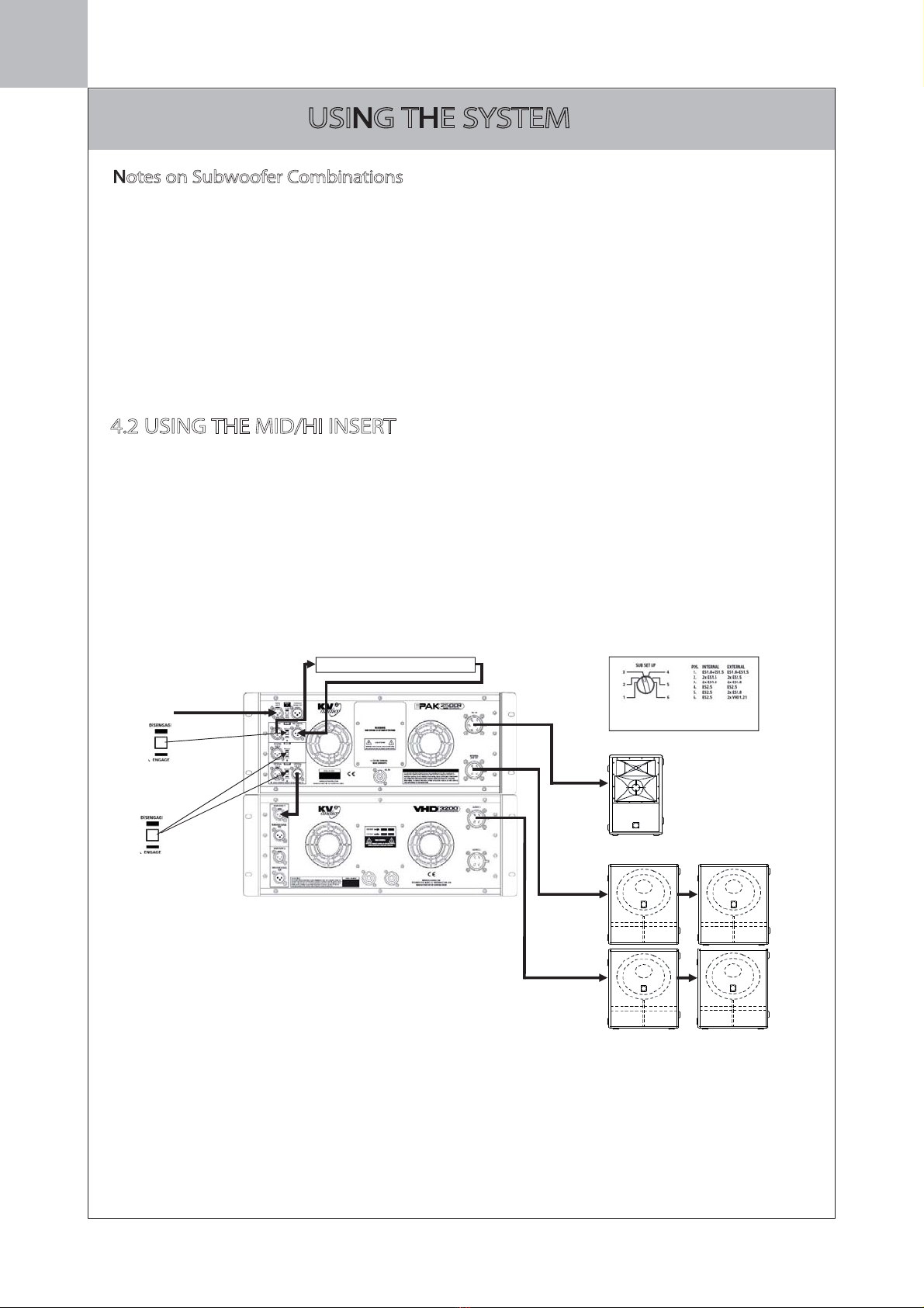
3)Mid/High In / Pre Control Out
This is an insert point for the Mid/High section
of the EPAK 2500R, the signal sent to the ES 1.0
cabinet. It enables you to ‘insert’ an external
device (a delay line for example) into the signal
that is being sent to the ES 1.0. With the
associated switch in the ‘Engage’ setting the Pre
Control Out connector would send the signal to
the external device, and its output would be
returned into the Mid/High In connector.
4)Internal Sub In
This ‘insert’ point allows you to drive the
internal subwoofer ampli rom an external
source. The signal for the internal subwoofer
r is usually derived from the Main Input
on the EPAK 2500R but with this Sub In and
associated switch the option is available to
derive the signal input for the internal
subwoofer section from a di rent source. For
further information see ‘Using the System’.
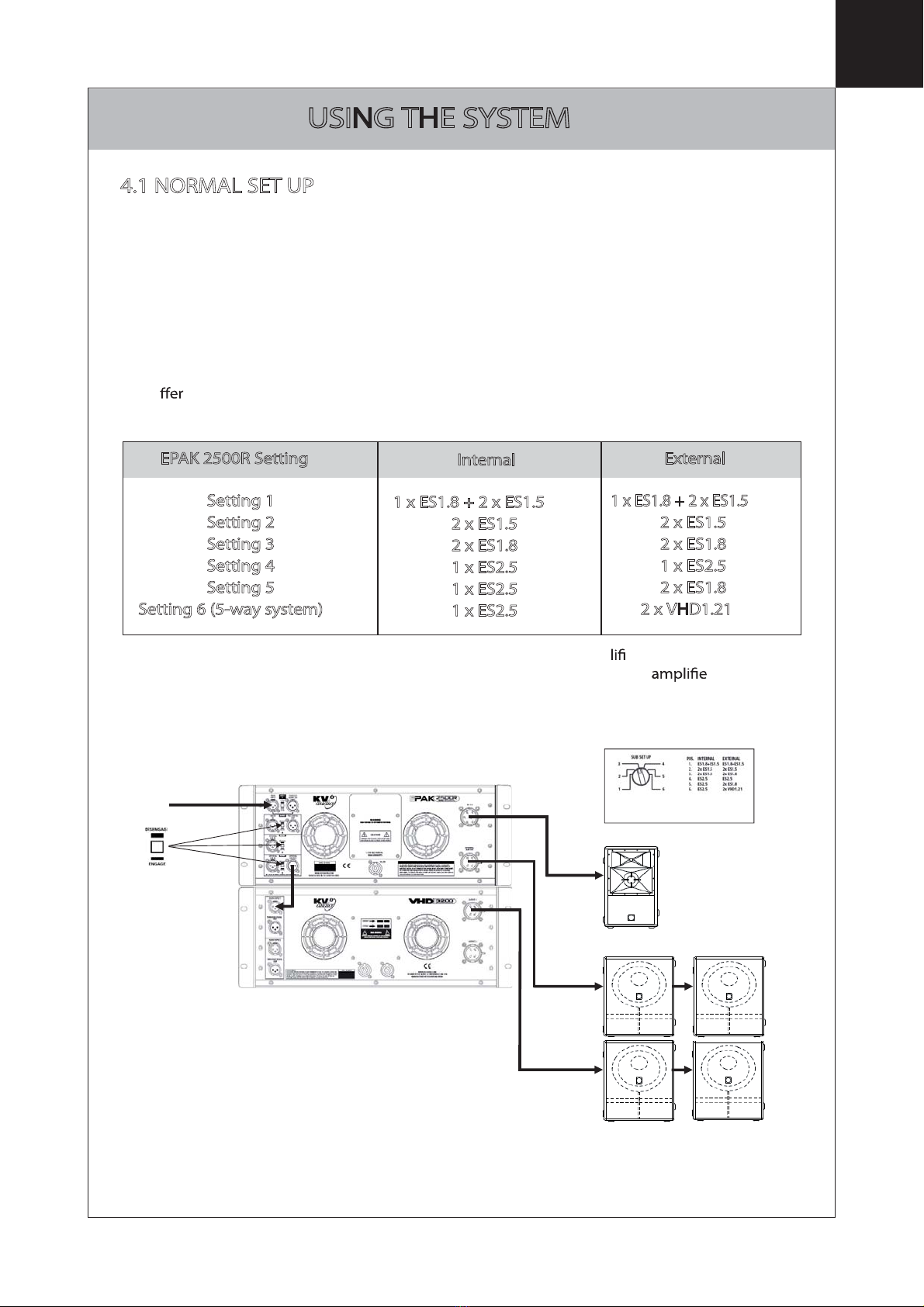
5)External Sub In, External Sub Out
Apart from providing signal processing and
power for driving the ES 1.0
enclosure and ES subwoofers the EPAK 2500R
also provides processed outputs for feeding
VHD 3200 subwoofer to drive various
combinations of ES and VHD subwoofers. The
signal for this is usually derived from the Main
Input on the EPAK 2500R but with these Sub In
and Sub Out connectors and associated switch
the option is available to derive the signal input
for the external subwoofer section from a
derent source. For further information see
‘Using the System’.
6) PowerCon Power Connector
Accepts a standard PowerCon terminated AC cable
7) Fans
The cooling fans operate continuously while the
EPAK 2500R is on. An internal temperature
sensor increases the speed of the fans during
high temperature conditions. Air enters through
the front grille and exits through the rear. Be
sure to allow adequ ow to the front of
the rack in which the EPAK 2500R is mounted.
8)ES 1.0 EP6 Connector
Accepts a standard EP6 terminated loudspeaker
cable for connecting up to a single ES 1.0
cabinet. We recommend using 2.5mm/core
cables.
9)Internal Sub EP4 Connector
Accepts a standard EP4 terminated loudspeaker
cable for connecting up to various ES series
subwoofers. We recommend using 2.5mm/core
cables.
1 3 4 6 7 8
2 5 9
3
3.2 REAR PANEL

4
USING THE SYSTEM
The EPAK 2500R is designed to actively power one ES 1.0 cabinet and associated subwoofer
systems. For Normal Mode operation signal is applied to the ‘Main Input’ connector and all the
‘Insert’ switches would be in the ‘Disengage’ position.
The Input Z switch should be set to match the output impedance of the device feeding the
EPAK 2500R. If you are using a VHD LD4 Line Driver then the Input Z switch on the EPAK
2500R should be set to 50Ω. If when using the LD4 you are feeding more than one EPAK
2500R then they should all be set to 10kΩwith the last one in the signal chain set to 50 Ω.
Six di ent combinations of sub woofers are accommodated for when using the EPAK 2500R.
The combinations are as follows:
‘Internal’ denotes subwoofers powered by the internal subwoofer amp er.
‘External’ denotes subwoofers powered by an external VHD 3200 subwoofer r, fed
from the EPAK 2500R’s External Sub Out connector.
EPAK 2500R Setting
Setting 1
Setting 2
Setting 3
Setting 4
Setting 5
Setting 6 (5-way system)
Internal
1x ES1.8 + 2 x ES1.5 1
2x ES1.5 2
2x ES1.8
1x ES2.5
1x ES2.5
1x ES2.5
External
1x ES1.8 + 2 x ES1.5 1
2x ES1.5 2
2x ES1.8
1x ES2.5
2x ES1.8
2x VHD1.21 3
Sub Set Up switch on front
panel at position 3
All Insert switches
in ‘Disengage’
position
Main Signal Input
ES 1.0
ES 1.8
ES 1.8
4.1 NORMAL SET UP

The Mid/Hi Insert point gives you the ability to ‘insert’ a signal processing device into
the ES 1.0 signal chain. For instance in some instances it may be necessary to ‘delay’
the signal going to the ES 1.0 using a delay line. The Main Input is used as the system
input, as per Normal Mode, but the Mid/Hi insert switch is switched to ‘Engage’. A
feed is taken to the delay line from the ‘Pre Control Out’ connector and the return
from the delay line is connected to the ‘Mid/Hi In’ connector as per the diagram:
USING THE SYSTEM
4
Sub Set Up switch on front
panel at position 3
All Sub Insert
switches in
‘Disengage’
position
Main Signal Input
ES 1.0
ES 1.8
ES 1.8
DELAY LINE
Mid Hi Insert
switch in
‘Engage’
position
4.2 USING THE MID/HI INSERT
Notes on Subwoofer Combinations
1. Setting 1 is set up for driving 1 x ES1.8 + 2 x ES1.5. It can also drive 1 x ES1.8 + 1 x ES1.5,
in this mode the relevant Sub level control (either Internal or External) should be increased by
up to +6dB.
2. Setting 2 is set up for driving 2 x ES1.5. It can also drive 3 x ES1.5, in this mode the relevant
Sub level control (either Internal or External) should be decreased by -3dB. This setting can
also drive just 1 x ES1.5 with the relevant Sub level control adjusted accordingly, dependant
on the application.
3. Setting 6 is a true 5-way setting. The ES2.5’s are actively crossed over with the VHD1.21’s.

4
USING THE SYSTEM
Taking the following diagram as an example, if the ES 1.0 was ying you might want
to one ES 2.5 above it with the other two ES 1.8’s ground stacked beneath. In this
instance it would be preferable to have both sets of subwoofers fed by separate feeds
from the mixing console, to give you independent level control to each of the
subwoofer types, and to have the ES 1.0 fed by the main output from the mixing
console:
The table below shows the various combinations of the Sub Insert switches and their
on the signal routing in the EPAK 2500R:
4.3 FEEDING SUBWOOFERS FROM ANOTHER SOURCE
InternalSub
InsertSwitch
Position
Disengage(Out)
Engage(In)
Engage
Disengage
External Sub
Insert Switch
Position
Disengage
Disengage
Engage
Engage
Internal Sub
Signal derived
from
Main Input
Internal Sub In
Internal Sub In
Main Input
External Sub
Signal derived
from
Main Input
Internal Sub In
External Sub In
External Sub In
Main signal input
Flown Subwoofer
feed from Mixing
console
Ground stacked
Subwoofer feed from
Mixing console
Both Sub Insert
switches in
'Engage position'
ES1.0
ES2.5
2x
ES1.8
Sub Set Up switch on front
panel at position 5

EPAK 2500R AMPLIFIER / CONTROLLER
SPECIFICATIONS
5
High Frequency Amplier Specication
Type Class AB Push-Pull low inter-modulation
Mosfet design with transformer
balanced out
p
ut
Rated Continuous Power 100W
Distortion <0.05%
O
p
eratin
g
Bandwidth 2.5kHz - 28kHz
Mid Frequency Amplier Specication
Type Class AB Push-Pull low inter-modulation
Mosfet design with transformer
balanced out
p
ut
Rated Continuous Power 200W
Distortion <0.05%
O
p
eratin
g
Bandwidth 500Hz - 2.5kHz
Mid-Bass Frequency Amplier Specication
Type High eciency, Low frequency, Current-
enhancin
g
switch mode
Rated Continuous Power 600W
Distortion <0.05%
O
p
eratin
g
Bandwidth 130Hz - 500Hz
Low Frequency Amplier Specication
Type High eciency, Low frequency, Current-
enhancin
g
switch mode
Rated Continuous Power 1600W
Distortion <0.05%
O
p
eratin
g
Bandwidth 20Hz - 130Hz
Speaker Input
S
p
eaker In
p
ut - / EP6 (Mid-Hi), EP4 (Sub)
Signal Input
In
p
ut Sensitivit
y
1.0V RMS
In
p
ut Im
p
edance 20kΩ or 50Ω "Line Driver read
y
"
Power Requirements
Power Connector Neutrik PowerCon®
Operating Voltage 100-120V@60Hz | 205-240V@50Hz | 225-
260V@50Hz
Recommended Am
p
era
g
e20A 115V
|
10A 230V
|
10A 250V
Physical Dimensions
Hei
g
ht 177.8mm (7.0")
Width 483mm (19.0")
De
p
th 495mm (19.5")
Wei
g
ht 30k
g
(66lbs)

MAIN
INPUT
MAIN
AC IN
THROUGH
SIGNAL OUT
CONTROL
PRE
INPUT
IMPEDANCE
MID/HI
INPUT
PRE CONTROL
OUTPUT
INTERNAL
SUB IN
DISENGAGE
ENGAGE
DISENGAGE
ENGAGE
10kΩ50Ω
DISENGAGE
ENGAGE
EXTERNAL
INPUT EXTERNAL
SUB OUT
PROTECTION
POWER SUPPLY
SIGNAL
MANAGEMENT
CONTROL
UNIT
HI
2,5kHz-40kHz
100 WV
OUTPUT
ES1.0
MIDHI
450 Hz - 2,5 kHz
200 W
MIDLOW
125Hz-450Hz
600W
SUB SET UP
EXT SUB LEVEL
±6dB
SUB LEVEL
±6dB
MASTER
LEVEL
±6dB
HI FREQ
LEVEL
±3dB
ES1.0 SYSTEM
1 PER SIDE
2 PER SIDE
INTERNAL
SUB OUT
LOW
20 Hz - 125 Hz
1800 W
SIGNAL
PRESENT
UNPROPER
USE LIMIT
SERVICEPOWER THERMAL
PROTECTION
6

WARRANTY, SERVICE & CONTACT
INFORMATION
WARRANTY
Your EPAK 2500R is covered against defects in material and workmanship.
Refer to your supplier for more details.
SERVICE
In the unlikely event that your EPAK 2500R develops a problem, it must be returned to an
authorized distributor, service centre or shipped directly to our factory. Because of the
complexity of the design and the risk of electrical shock, all repairs must be attempted
only by quali technical personnel.
If the unit needs to be shipped back to the factory, it must be sent in its original carton. If
improperly packed, the unit may be damaged.
To obtain service, contact your nearest KV2 Audio Service Centre, Distributor or Dealer.
7


The future of sound.
Made perfectly clear.
KV2 Audio, Nádražní 936, 399 01 Milevsko, Czech Republic
T +44(0)1423 816868 F +44(0)1423 816869
www.kv2audio.com
KVV120030-00-02-0
At KV2 Audio our vision is to constantly develop
technologies that eliminate distortion and
loss of information providing a true dynamic
representation of the source.
Our aim is to create audio products that absorb
you, place you within the performance and deliver
a listening experience beyond expectation.
Other manuals for EPAK2500R
1
Table of contents
Other KV2 Audio Music Equipment manuals
Popular Music Equipment manuals by other brands

Blue Lantern Modules
Blue Lantern Modules BLM JP JFET MK2 SAW CORE VCO instructions

Electrix
Electrix FilterQueen owner's manual

Ibanez
Ibanez WS1 owner's manual

Solid State Logic
Solid State Logic SSL12 quick start guide

Shift Line
Shift Line Stages Dynamic Drive user guide

Velleman
Velleman K4401 Illustrated assembly manual