API 272.98400.490 Datasheet

ARROW LINE
DUAL SEWING CENTER
(Desk Only)
Model Number: 272.98400A90 (Oak)
272,98401.490 (White)
Assembly Instructions and Parts List
IMPORTANT: Please read these instructions before assembling desk.
Assemble contents of carton #1 of 3 and #2 of 3 first.
98400-FC
98401-FC

Notice to Customer:
Before beginning assembly, remove all parts from the
carton. Check closely with illustrations below to determine
that all the parts are included.
For assembly or operating assistance, or to report any
missing or damaged parts, you may call or write to:
1-800-533-7347
API Specialty Furniture
(A division of ARROW Products Inc.)
P.O. Box 410, Elkhorn, Wl 53121
TO ORDER REPLACEMENT PARTS CALL
1-800-366-7278
PLEASE NOTE: To assure proper handling of replacement
parts please include the following information;
Model Number of Unit - 272.98400.490 (Oak)
272.98401.490 (White)
Part Number of Part Required
Your Name, Address, and Phone Number
Top
Right Leaf Left Leaf
Front
/ /
Back
./ ./
Back Brace
/. ,.-7
Left Side
Panel
Left Door
Right Side
Panel
•/
./
Right Door
/./
8erger
Platform
Left
Leaf Support
Tote Tray
Cover Platform /_
Lift Panel
w/Lift
Page 1
Door Stop
98400-1
98401-1

(22)
(13)
#8xl/2" Panhead Screw
#5x1/2" Flathead Screw
(11) #8x5/8" Flathead Screw
(2) #8x7/8" Machine Screw
(98401only)
Ceramic Knob//\\\///\\//\\/\\/\//\\\\/\\/\\\//\\//'_Bolt
(2)
(6)
(8)
(6)
(8)
(1)
(4)
Mounting Bolts
Wing Nuts
%¢>
6mm Hex Nuts
©
Hardware Included
6mm Hexhead Bolt
(18) Cams_
(12) #5x5/8" Flathead t',_l
8orawe _1
(2) Non-Locking
Casters
]
(8) 6mm Flat _ 1
Washers
Q
(2) Lockin!
Casters
(1) Bronze Strike Washer (1) Round Magnet
Q @
(1) Right Wing (1) Left Wing
(4) Door Hinge
r. 1° I °1
I° o_ o Ho
(1) Leaf I o H o I
Support I tl I
Block
(2) Door Catch Pins
_] I_ L_--_o; 2) Kn°bs ite_C_ra
Zinc Flat Washers •_(2) Door Catches
Metal Knob Wh mic
(98400 only) (98401 only)
[p,,,,,.,..
(2) 8/32x1" Metal Knob
Bolt 98400
(2) Support Hinge
(4) Plastic Trays
(1) Large
(3) Small
(1) J-Hook
Allen Key (6) Sponge Dots (1) Leaf Support Cleat
Caster Clips
(1) 10132" Wing Nut (1) Tote Tray
(4) Caster Insert JJl_,.
_'- _ (1) 3/16" Washer
Q
(18) Connecting Bolts
Page 2
(5) Adjustable
%(1) Spring Hinge
(3) 1-1/2" Titus Screw
(1) Custom Fit
Insert (Hook)
(1) Self Sticking
Rubber Tab
98400-2
98401-2

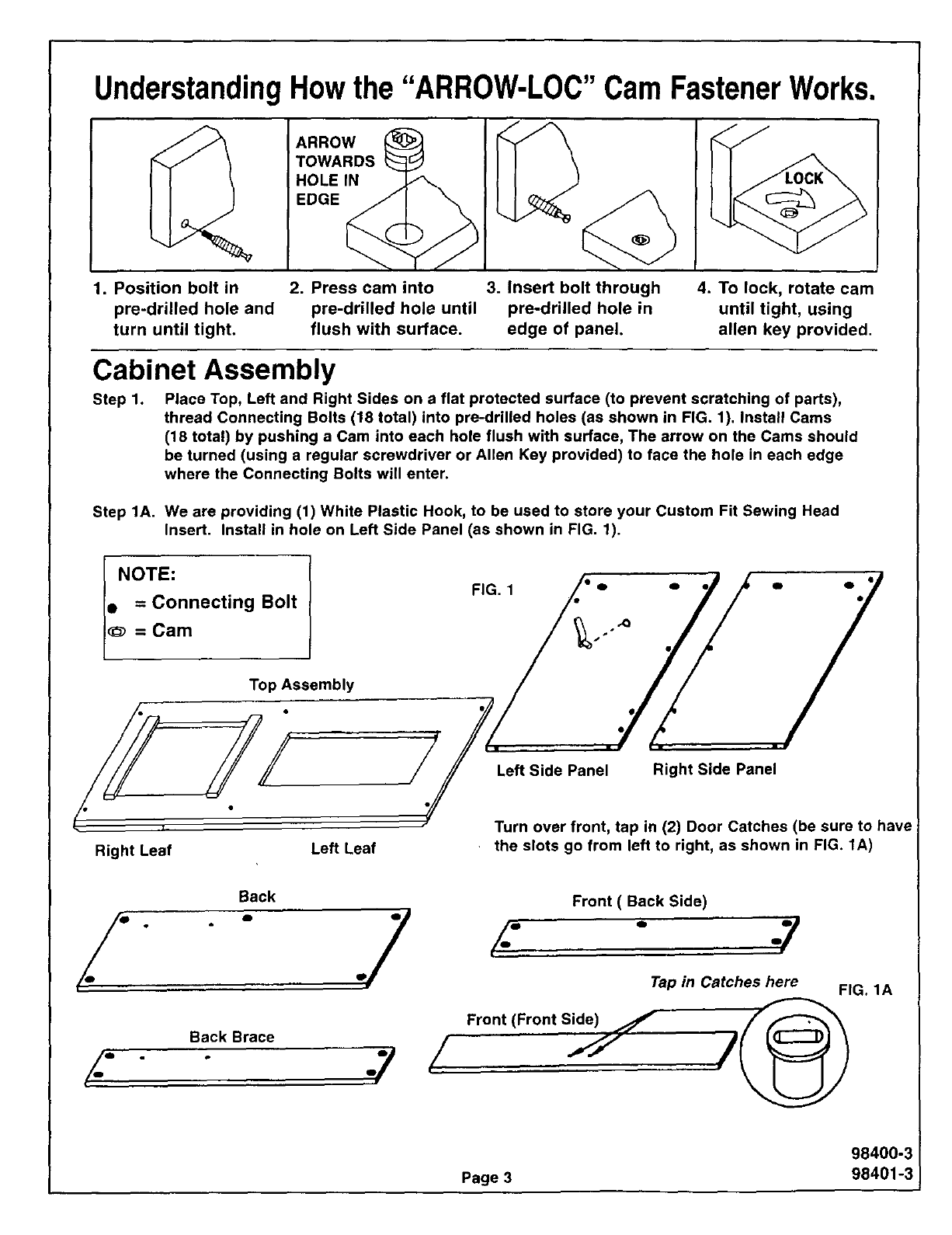
UnderstandingHowthe "ARROW-LOC" Cam FastenerWorks.
ARROW
TOWARDS
HOLEIN
EDGE
1. Position bolt in 2. Press cam into 3. Insert bolt through
pre-drilled hole and pre-drilled hole until pre-drilled hole in
turn until tight, flush with surface, edge of panel.
4. To lock, rotate cam
until tight, using
allen key provided.
Cabinet Assembly
Step 1. Place Top, Left and Right Sides on a flat protected surface (to prevent scratching of parts),
thread Connecting Bolts (18 total) into pre-drilled holes (as shown in FIG. 1). Install Cams
(18 total) by pushing a Cam into each hole flush with surface, The arrow on the Cams should
be turned (using a regular screwdriver or Allen Key provided) to face the hole in each edge
where the Connecting Bolts will enter.
Step 1A. We are providing (1) White Plastic Hook, to be used to store your Custom Fit Sewing Head
Insert. Install in hole on Left Side Panel (as shown in FIG. 1).
INOTE:
• = Connecting Bolt
= Cam
FIG. 1
Top Assembly
/iJJ
Right Leaf Left Leaf
Back
./ " .7
Back Brace
Left Side Panel Right Side Panel
Turn over front, tap in (2) Door Catches (be sure to have
the slots go from left to right, as shown in FIG. 1A)
/- #
Front ( Back Side)
/. ..y
Tap in Catches here FIG. 1A
Front (Front Side)
/1I /
98400-3
Page 3 98401-3

Step 2; Assemble J-Hook, Washer and Wing Nut to Spring Hinge (as shown in FIG. 2).
Install J-Hook Assembly to Front with (2) #8xl/2" Panhead Screws. Check that the J-Hook swings
under bottom edge of Front (as shown in FIG. 2A).
FIG. 2A
Step 3. Attach Back by guiding onto (2) Bolts in Right Side. Turn Cams to locked position, using screwdriver
or allen key.
Attach Front (taped edge up) to Right Side, guiding Front onto (2) Bolts. Turn Cams to locked
positions, using screwdriver or allen key.
Attach Brace (taped edge down) to Right Side with CAMS TOWARD REAR of unit, guiding Brace onto
(2) Bolts. Turn Cams into locked position, using screwdriver or allen key (as shown in FIG 3).
CAUTION:
AFTER INSTALLING BRACE, HOLD BRACE TO AVOID PRESSURE ON BOLTS UNTIL LEFT SIDE iS ATTACHED,
OR TURN UNIT ONTO RIGHT SIDE.
Right Side Panel
Back Brace
Back
I
Front
Taped Edge
98400-4
Page 4 98401-4

Step 4. Attach Left Side to Brace, Back and Front, guiding Bolts into holes. Turn Cams to locked
position, using screwdriver or allen key (as shown in FIG. 4).
FIG. 4
Brace
Front
Lea Side
Step 5. Install Caster Clips over holes in Sides, tap in Caster Inserts, Insert stems of Casters into Caster
Inserts. Tap in by hand or use a hammer with padding to prevent damage. Locking in front
Non-Locking in rear (as shown in FIG. 5).
VERY CAREFULLY, WITH HELP, TURN CABINET OVER ONTO CASTERS.
Caster
FIG. 5
_C L°cking
Caster
aster Insert
Caster Clip
Caster Insert --....
Caster Clip
98400-5
Page 598401-5

Step 6. Attach the Left and Right Wing to the Platform using (4) #8x1/2" Panhead Screws (as shown in
FIG. 6). The long flanges facing outward and toward edge of Platform.
FIG. 6
#8x1/2" Panhead
Screws
Platform
Step 7. Attach the Wings (with Platform) to the Carriage of the Lift Mechanism by laying the Back (with Lift
attached) in a flat position and aligning the top and bottom holes in Wing flanges with the holes in
the Lift Carriage. Insert the (8) 6mm Hex Head Bolts through the Wings and Carriage and attach a
Washer & Hex Nut to each Bolt (as shown in FIG. 7). Before tightening the Nuts and Bolts using a
10mm wrench or adjustable wrench or pliers, use a square or the bottom shelf of cabinet to square
the platform with the back (as shown in FIG. 7B). Final assembly should look FIG. 7A.
FIG. 7A FIG. 7
"r-'-"l I
@
@
Hex Head Nut
FIG. 7B
Washer
Lift Carriage
Machine Platform
6mmxllmm Hex Head Bolt
98400-6
Page 6 98401-6

Step8. Attachthe(4)plasticTraysto theDoorbyinsertingthe(16)#8xl/2" PanheadScrewsintotheDoor.
Attach(3)SmallTraysin thetopthreerowsof pre-drilledholesandLargeTrayin thebottomrow.
Screwin(1)DoorCatchPinin eachDoor.Attach(2)DoorHingesineachDoorwith(6)#5xl/2"
Screws (as shown in FIGS, 8 and 8A). Loncl end attaches to door. Attach Door Stop using (3) #8x5/8"
Flathead Screws.
Door Catch Pin /\\
FIG. 8Ao
0 0
0 0
Note:
Long Side
To Door
#5xl/2" Flathead
Screw
/
Door Catch Pin
f
f I Door Stop
Left Door Right Door
Step 9. Attach (2) Support Hinges to Left Support with (4) #8x5/8" Flathead Screws; insert (1) round Magnet
into hole in Leaf Support (as shown in FIG. 9). Attach Self Sticking Rubber Tab to Leaf Support even
with end & edge.
Left Leaf Support
Self-Sticking
Rubber Tab
#8x5/8" t
Flathead Screw
Round Magnet
98400-7
Page 7 98401-7

Step 10. Attach Back Panel (with Lift, Wings and Platform attached) to Cabinet back Brace with
(4) 1/4"x2" Carriage Bolts. Insert the Top 2 Bolts in Cabinet Back. Hang the Back Panel from the top
Bolts, put on Washer and Wing Nuts, then start and put on the remainder Bolts, Nuts and Washer,
tighten (as shown in FIG. 10).
1/4"x2" Carriage
Bolts FIG. 10 Back Panel
Platform and Lift Assy.
1/4" Washer
1/4" Wing Nut
Cabinet Assy.
Step 11. Attach the (1) Leaf Support Wing to outside of Left Side, with (4) #8x5/8" Flathead Screws. Now,
attach the (1) Bronze Strike Washer for the Round Magnet to the side with (1) #5xl/2" Flathead Screw
(as shown in FIG. 11).
FIG. 11
@
Rear View
Back
®
(///_ o#5x112"Screw-
oo Strike -_./_//
/
O O
004 LeftWing
- Round Magnet
// _>-_ #8xs/8"
Flethead Screw
JNote:
Support Wing is to fold
toward rear of cabinet.
98400-8
Page 8 98401-8

Step 12. With an assistant, grasp the Top and Leaves together (top assembly) and turn the Top over and
guide the Connecting Bolts into the corresponding holes in the Sides, Front and Back
(as shown in FIG. 12). Reach behind Front and turn the Cams to the locked positions on the Right
Side, Back and Front. Open Large Leaf, resting it on the Leaf Support, turn Cams to the locked
position. Some adjustment in the location of the Platform can be made so as to permit Freearm
position (see page 12). Just loosen the Screws holding the Platform to the Wings;
align and retighten.
Leaf Support
FIG. 12
I
F l
Top Assembly
Front View
J
98400-9
Page 9 98401-9

Step 13. The Doors may be hung using (12) #5x5/8" Flathead Screws (as shown in FIG. 13). Next
attach the Door Knobs using (2) 7/8" Bolts For Ceramic Knobs -- (2) 8/32x1" Bolts for
Metal Knobs. This is a 2 Pc, Knob assembly as shown in Fig. 13.B. Slide the Sleeve End onto
the Post End of the Knob and attach to door.
Step 13A. Attach Leaf Support Block to the back of Top in pre-drilled holes with (2) #8x1_" Titus Screws
(as shown in FIG. 13A). FIG. 13.B
Metal Knob
98400 only) Ceramic Knob
_(98401 only)
Screws
8/32xl "Bolts f
7/8" Bolts
\
FIG. 13 /
FIG. 13A
I
t
# #
• f
#• •
/
_CeramicKnob
# (98401 only)
t
•i/_Metal Knob
// 1(98400only)
o o
#5x5/8" _f_----_
Screws
8/32x1" Bolts"_._
7/8" Bolts
Stop at this point and assemble the Caddy
98400-10
Page 10 98401-10

Step 14. To attach Caddy swing hinged hook from behind the desk front, to position (as shown in FiG. 14).
Lift Overlock Leaf and guide hook into hole in bottom side of Overlock Leaf.
FIG. 14
Overlock Leaf
J-Hook Assembly
Overlock Leaf
ASSEMBLING AND INSTALLING SERGER PLATFORM
Step 15. Assemble parts to Serger Platform:
Glides A.
Serger Platform
(Bottom)
Leaf Support Cleat 1-1/2"
Titus
Screw
Glide _
0
Cork Dot
Page 11
Attach small wooden leaf support cleat
to Serger Platform with one (1) #8x1-1/2"
Titus Flathead Screw. Attach one Cork
Dot to end of adjustment glide, Adjust
1-1/2" screw so that it is just loose
enough to allow the cleat to be turned for
storage.
B. Install adjustable glides into four inserts
in Serger Platform and into end of Cleat.
C. Store Serger Platform in Caddy when not
in use.
98400-11
98401-11

Step 16. Place Serger Platform on Overlock Leaf. Raise Support Leg, open front Leaf and rest on Support
Leg. Adjust height of Platform, for your machine, by turning adjustable Legs, until your machine is
level with Leaf (as shown in FIG. 15). Store Serger and Platform in bottom of Caddy.
FIG. 15
Serger Platform
Step 17. To store Caddy, unhook Overlock Leaf and let down along side of Caddy. Roll Caddy cabinet as for
to the right as possible to avoid interference when sewing machine is in storage.
Closed Position
O
o
98400-12
Page 12 98401-12

Installing Sewing Machine into Your
It may be helpful to read the directions for operating
the mechanism before proceeding with the following
steps. See page 15, and FIG. 19 on next page.
let.
FIG. 16
Step 1. Swing out the Leaf Support Wing and open leaves.
To prevent damage to Cabinet surface, place
cushioning material just to the left of cut-out. Lay the
machine on its back, on top of cushioning material.
Step 2. Take the cord from the foot control up from the bottom
through the slot on the right end of the cabinet Platform (see FIG. 16).
Step 3. Plug the cord into the right end of the sewing machine (see FIG. 17).
IMPORTANT: Do not place sewing machine to far out onto the
Leaf. The extra weight may cause the cabinet to flip over. This
could cause personal injury or damage to the cabinet and sewing machine.
Installing Sewing Machine Head
VERY CAREFULLY ATTACH THE SEWING MACHINE TO
THE CABINET IN THE FOLLOWING MANNER:
Step 4. Remove the extension table on the left side
of the sewing machine (Free Arm Position).
If it is detachable.
Step 5. Thread the (2 provided) Headmounting Bolts
into the two threaded holes located on the
bottom of your machine; twist tight to the
collar. Number and type of Bolts may vary
with different machines (see FIG. 18).
FIG. 18A l
®
Step 6. Locate the appropriate platform holes
which position your machine in the top opening
to allow for use of the CUSTOM FIT plastic insert
(Sears Item #9801) when sewing in the flatbedx
position. See Fig. 18 and Photo C on Page 14.
For assistance in locating the appropriate
platform holes please refer to FIG. 18B.
on page 15.
Next, secure machine to Platform with
Washers and Wing Nuts by tightening
into place from underneath Platform
(see FIG. 18A).
Step 7. Lower machine onto the platform, alignin!
bolts with the holes selected in the
platform. Some Machines may require
new holes to be drilled.
Step 8. Pushing the machine down, lower it
into the storage position; lift back
into the free-arm position, to check
operation.
Refer to operating instructions of the Air Lift
Mechanism on page 15.
Maintenance of Cabinet:
Clean as you do your other fine furniture.
using a soft cloth and polish.
Cabinet
Custom Fit Insert
FIG. 18
/
Page 13
o O
ilI
98400-13
98401-13

HOW TO MOVE YOUR MACHINE
FROM ONE POSITION TO ANOTHER
To move machine from free arm to flatbed (see Photos
A,B& C).
GENTLY push down on sewing machine until you hear
a "cLick."
The sewing machine is now locked in _lace at the
flatbed position,
To move machine from flatbed to storage (see Photos
C,D & E.
GENTLY push down on sewing machine until you hear
a "click."
The sewing machine is now locked in place at the stor-
age position,
NOTE: Your mechanism is adjustable. You can adjus_
up or down by loosening the 2 hex nuts on the cam
lock. After moving to the desired position retighten.
PHOTO A-FREE ARM POSITION
PHOTO D
PHOTO 8
PHOTO C-FLAT_ED POSITION Page 14
PHOTO E-STORAGE POSITION
To move machine from storage to flatbed (see Photos
E&C).
VERY GENTLY push down until you hear a "click" and
release.
The sewing machine will now move up to the flatbed
position.
To move machine from flatbed to free arm {see Photos
C&B_.
VERY GENTLY push down until you hear a click and
release.
The sewing machine w{l! now move up to the the lree
arm position. For sonde machines _jou may have to lift
slightly to lock into the freearm position. 98400-14
98401-14

To assist in selecting the platform holes best suited to properly position your sewing
machine, refer to FIG. 18B below.
:ustom Fit Insert (Sears #9801)
FiG. 18B
Sewing Machine Cabinet top Opening
Determine measurement A & B on your custom-fit plastic insert and select platform holes
which will properly place your machine in the cabinet top opening to allow it to fit with
the insert when sewing in the flatbed position,
CAUTION:
This cabinet is equipped with a vertical Air-Lift Mechanism which is powered by gas filled
cylinder to aid in raising and lowering the sewing machine. PLEASE DO NOT OPERATE THE
MECHANISM UNTIL YOU HAVE MOUNTED YOUR SEWING MACHINE ON THE PLATFORM
(SEE PAGE 13).
Because gas filled cylinder is heavy duty do not let go of machine and platform when moving
from one position to the other.
To move the Platform to any position please follow the instructions on page 14.
Freearm Position U
FIG. 19
.._9
Flatbed Position U
!o
I
Storage Position __J
98400-15
Page 15 98401-15

Wood Parts List
(A) Rear Leaf
///,I
(C) Front Leaf
Top Assembly /"
(B) Top _'_v'/
-(D) Left Leaf
QV a "/
(E) Left Side Panel iJ
(F) Right Side Panel
(G) Front
/"!
m
z/"
(I) Back Brace •
/- a,
(J) Left Door (K) Right Door
(N) Serger
Platform
(L) Lift Panel (M) Door Stop
(O) Tote Tray Cover
/....../
(P) Platform
_(Q) Le; (R) Leaf Support
f Support
leat
REF. DESCRIPTION
A Rear Leaf
B Top
C Front Leaf
D Left Leaf
E Left Side Panel
F Right Side Panel
G Front
H Back
I Back Brace
PART #
98400(OAK)
003042
003039
003041
003040
003043
003044
003048
003045
003047
PART #
_8401(WHITE)
003123
003120
003122
003121
003124
003125
003092
003126
003128
DESCRIPTIONRER
J Left Door
K Right Door
L Lift Panel
M Door Stop
N Serger Platform
O Tote Tray Cover
P Platform
Q Leaf Support Cleat
RLeaf Support
PART #
98400(OAK)
003050
003051
003046
003053
003062
003052
003049
002723
003012
PART #
98401 (WHITE)
003093
003094
003127
003136
003102
003135
003133
002723
003077
98400-1E
Page 16 98401-1E

(A)
(B)
#8xl/2" Panhead Screw
#5xl/2" Flathead Screw
(C) #8x5/8" Flathead Screw
(D) #8x7/8" Machine Screw
(98401 only)
(E)
(F)
(G)
(H)
(D
(J)
(K)
(L)
(M)
Mounting Bolts
Wing Nuts
6mm Hex Nuts
©
Hardware Included
(N) Cams
(11) #5x5/8" Flathead
Screws
(AA) Right Wing (BB) Left Wing
(CC) Door Hinge
O Non-Lock,ng
(V) Locking 0 0
Casters _ Casters _ _ 0
(JJ)v6__ _11 MM) LeafSupport O u_ n
Block (DD) S ge
(OO)
Custom
Fit Insert
(Hook)
(P) Bronze Strike Washer (W) Round Magnet
Ceramic_
(KK) White
(Q) Metal
(98400 only) (98401 only)
(EE) Plastic Trays Small
(QQ) Large
Zinc Flat Washers []_ _Knobs
(LL) 8/32x1" Bolt 98400 Only
6mm Hexhead Bolt (R) Carriage Bolts
(X) Door Catches
(X) Door Catch Pins (FF) J-Hook
)1-1/2" Titus Screw
Allen Key (S) Leaf Hinge
I (__ (GG)GiAddeJUStable (HH) Spring Hinge
(PP)RuS;lbf'StiCTakbng _
Caster Clips
(T) 10132" Wing Nut (z) Tote Tray
Caster Insert . ""_J I1"1 (Y) Lift Mechanism
_(U) 3/16_her _ /_',,_'" _'_
98400-17
Page 17 98401-17
Connecting Bolts

Parts Numbers
_ef. No.
A
B
C
D
E
F
G
H
I
J
K
L
M
N
O
P
Q
R
S
T
U
V
W
X
Y
Z
Description
#8xl/2" Panhead Screw
#5xl/2" Flathead Screw
#8x5/8" Flathead Screw
#8x7/8" Machine Screw
Mounting Bolt
Wing Nut
6ram Hex Head Bolt
Zinc Flat Washer
6mm Hex Nut
Allen Key
Caster Clip
Caster Insert
Connecting Bolts
Cam
Non-Locking Caster
Bronze Strike Washer
Knob (98400 only)
Carriage Bolt
Leaf Hinge
10/32 Wing Nut
3/16" Washer
Locking Caster
Round Magnet
Door Catch and Pin
Lift Mechanism
Tote Tray
Pad No.
002614
000916
002570
000185
002890
00488
003176
000220
003172
000712
000324
000368
002892
000709
001136
000839
003170
001319
002733
002208
002207
001135
002854
002870
003167
002869
Ref. No. Description Part No,
AA Left Wing 003194
BB Right Wing 003193
CC Door Hinge 002613
DD Support Hinge 002734
EE Plastic Tray (Small) 003146
FF J-Hook 002206
GG Adjustable Glides 002643
HH Spring Hinge 002209
Manual 003150
II #5x5/8" Flathead Screw 002899
JJ 6mm Flat Washer 003190
KK White Ceramic Knob (9_01on_y) 003165
LL 8/32x1" Knob Bolt (98400only) 003192
MM Back Leaf Support Block 003195
OO (Custom Fit Insert) Hook 002251
PP Self Sticking RubberTab 003174
QQ Large Tray 003158
RR 1 1/2 Titus Screw 001212
98400-18
Page 18 98401-18

API Specialty Furniture
(A Division of ARROW PRODUCTS, Inc.)
P.O. Box 410, Elkhorn, Wl 53121
1-800-533-7347
12-98 98400-BC
98401-BC
This manual suits for next models
1
Table of contents